
Sandwich membranes through a two-dimensional confinement strategy for gas separation†
Zixi
Kang‡
a,
Sasa
Wang‡
a,
Rongming
Wang
 a,
Hailing
Guo
b,
Ben
Xu
a,
Shou
Feng
a,
Lili
Fan
a,
Liangkui
Zhu
c,
Wenpei
Kang
a,
Jia
Pang
a,
Hanyi
Sun
a,
Xinxin
Du
a,
Minghui
Zhang
a and
Daofeng
Sun
*a
a,
Hailing
Guo
b,
Ben
Xu
a,
Shou
Feng
a,
Lili
Fan
a,
Liangkui
Zhu
c,
Wenpei
Kang
a,
Jia
Pang
a,
Hanyi
Sun
a,
Xinxin
Du
a,
Minghui
Zhang
a and
Daofeng
Sun
*a
aCollege of Science, China University of Petroleum (East China), Qingdao, Shandong 266580, P. R. China. E-mail: dfsun@upc.edu.cn
bState Key Laboratory of Heavy Oil Processing, Key Laboratory of Catalysis, China National Petroleum Corp. (CNPC), China University of Petroleum (East China), Qingdao 266555, P. R. China
cState Key Laboratory of Inorganic Synthesis and Preparative Chemistry, Jilin University, Changchun 130012, P. R. China
First published on 20th August 2018
Abstract
Metal–organic frameworks (MOFs) with designable pore environments can be involved in graphene oxide (GO) layers as the filters to tailor the channels in laminar membranes for precise molecular separation. The well-distributed fillers, high compatibility between fillers and GO, and thin selective layers are critical aspects for capitalizing on the positive effect induced by the addition of a microporous phase. Herein, a two-dimensional confinement strategy for constructing the composite membrane is deduced by the in situ conversion of the metal hydroxide/GO precursors into MOF/GO “sandwich” membranes. This method is confirmed to be feasible for the creation of an ultra-thin composite membrane with uniform MOF filler dispersion and good compatibility with GO layers. The sandwich membranes show enhanced H2/CO2 separation performance: H2 permeance of 5922 ± 1000 GPU and H2/CO2 selectivity of 75 ± 4 at 25 °C, which is six-fold increased compared with the GO membrane. Due to the combination of GO and MOF, the membrane also exhibited a H2 permeance of 3654 ± 252 GPU and H2/CO2 selectivity of 31 ± 3 at 150 °C with the feed gas containing water vapor. Such a nanoscale confinement approach can be extended to other composite membranes, providing valuable insights into the design and development of advanced materials for membrane-based efficient molecular separation.
Introduction
Ultra-thin membranes with uniform pore size are promising candidates for efficient separation processes.1–6 Graphene oxide (GO), a type of two-dimensional material, can be engineered into ultra-thin membranes for molecular separation through the in-plane defects and the spacing between GO layers.7–10 However, the channels in GO membranes are of variable sizes and are difficult to tailor for the selective permeation of light gases and monovalent ions.7 Several pioneering studies have reported the adjustment of the interlayer spacing by cationic control,10 varying humidity,11 crosslinking and inserting other species, etc.12–16 Even so, significant efforts are still in demand for the development of uniform, high-density, sub-nanosized pores in GO membranes for the efficient sieving of light gases or small ions.9,10,17 Similar to doping porous materials into polymers to prepare mixed matrix membranes (MMMs),18–24 metal–organic frameworks (MOFs), microporous and designable materials with uniform pore sizes,25–30 can be intercalated into the gaps of GO layers as microporous fillers to sieve mixtures.31,32 Recently, Yao et al. reported a UiO-66-NH2/GO membrane that exhibited enhanced hydrogen separation performance with an ideal H2/N2 and H2/CO2 selectivity of 9.75 and 6.35, respectively.33 Zhang and Liu et al. prepared an antimicrobial ZIF-8/GO thin film nanocomposite membrane for nanofiltration.34 Zhong and Liu et al. reported MOF@GO membranes prepared by a pressure-assisted self-assembly filtration technique for pervaporation.35 Wang et al. studied the vacuum-assisted assembly of ZIF-8@GO composite membranes with enhanced organic solvent nanofiltration performance.36 There are some key points for producing MOFs/GO composite membranes for efficient molecular separation: (i) interfacial adhesion between the MOFs and GO layers; (ii) homogeneous dispersion of MOFs in the GO membrane; (iii) thin selective layers to give ideal permeance. Suitable strategies are required to fulfill these requirements based on the layered structure of the GO and crystal growth process of MOFs.Inspired by the filler nanosizing and in situ coordination strategies in the polymer MMMs system,19,22,37–40 a two-dimensional confinement conversion method was performed in this work to fabricate MOF/GO sandwich membranes by the in situ reaction of hydroxide nanosheets (NS)/GO precursor membranes and organic ligands.41,42 As illustrated in Scheme 1, metal hydroxides NS were evenly amalgamated with GO sheets and the metal hydroxides/GO membranes were fabricated via a vacuum filtration process. Subsequently, the incorporated metal hydroxide NS played the role of metal source, which were assembled in situ with organic linkers through the formation of coordination bonds. It is worth mentioning that the MOF fillers were generated in the layered GO matrix, thus resulting in their good combination. Moreover, due to the two-dimensional confinement effect of GO layers, the obtained membranes can maintain the uniform distribution of fillers and ultra-thin thickness.43 Through in situ temperature-dependent FTIR spectroscopy, it was found that CO2 molecules were sealed in the membrane, and we suggest that this is associated with the hydrogen bonds formed between CO2 and GO as well as CO2 and ZIF-67. The strong interaction between CO2 and the membrane further hindered the CO2 passage. Mixed gas permeance tests of the MOF/GO sandwich membranes were performed, and the results showed a highly enhanced selectivity for H2/CO2 separation. We are pleased to demonstrate that this two-dimensional confinement conversion strategy works well and should be generally applicable for other microporous materials/graphene oxide systems, such as the in situ crystallization of dry-gel precursors to zeolites in lamellar GO membranes.44,45
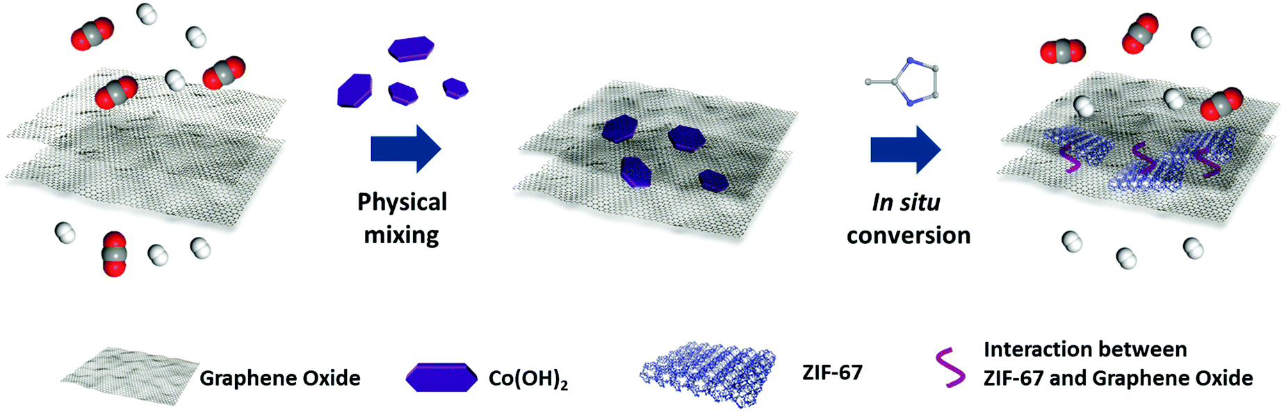 | ||
| Scheme 1 Schematic illustration of sandwich membranes through the two-dimensional confinement strategy for gas separation. | ||
Experimental
Materials
The nylon membrane filters (pore size 0.2 μm, diameter 47 mm) were obtained from GE. Graphene oxide (GO) was provided by XFNANO. Co(Ac)2·4H2O, 2-methylimidazole (2-MIM, 98%) was provided by Energy Chemical. Ammonia solution and hydrazine hydrate (85%) were supplied by Sinopharm Chemical Reagent Co. Ltd. All the chemical materials were used as received.Synthesis of Co(OH)2 NS
Co(Ac)2·4H2O (0.6225 g) was dissolved in 200 mL DI water, then 175 μL hydrazine hydrate (85%) and 5 mL ammonia solution were added into the solution, which was kept at 95 °C under backflow for 1.5 h. After self-cooling, the Co(OH)2 suspension was centrifuged and thoroughly washed several times with DI water and then dried at 80 °C.Preparation of Co(OH)2/GO-x and ZIF-67/GO-x membranes
GO (0.05 g) was dispersed in 500 mL DI water by sonication for 1 h to obtain the GO suspension (0.1 g L−1). Co(OH)2 NS (0.01 g) was dispersed into 75 mL DI water by sonication for 0.5 h. GO suspension (25 mL) was added to the suspension above by sonication for 0.5 h to form a Co(OH)2/GO suspension. The Co(OH)2/GO-x membranes (x was the volume of Co(OH)2 NS/GO suspension in mL) with different thicknesses were obtained by filtration of different volumes of Co(OH)2/GO suspension (20 mL, 25 mL, 30 mL, 35 mL, 40 mL) onto the nylon substrates. 2-MIM solution (50 mL, 20 g L−1) was filtered on the Co(OH)2/GO-x membranes for 48 h to convert Co(OH)2 to ZIF-67. When the color of the membrane was changed to purple, the ZIF-67/GO-x membranes were obtained.Preparation of ZIF-67/GO-D membranes
Nano-sized ZIF-67 crystals (1.52 mg, referred to ZIF-67 NC) were dispersed into 75 mL DI water by sonication for 0.5 h. GO suspension (25 mL, 0.1 g L−1) was added into the suspension above and with sonication for 0.5 h. Dispersions (20 mL, 30 mL, 40 mL) were filtered onto nylon support to obtain ZIF-67/GO-D membranes.Characterization
The morphologies of all materials and membranes were observed with a scanning electron microscope (SEM, HITACHI, S4800). TEM images were obtained with a JEM-2100 (JEOL Co. Japan) at the accelerating voltage of 200 kV. A Bruker atomic force microscope (AFM) instrument was used to investigate the microcosmic structure of the prepared materials. In order to obtain AFM images, samples were dripped and dried on the Si wafer and imaged on a commercial Multi-Mode Scanning Probe Microscope with a NanoScope IVa controller in contact mode. For the membrane samples, the composite membranes were scraped from the nylon supports and dispersed in the ethanol via sonication. After second order flattening, all image heights were directly analyzed using NanoScope Analysis software and an Ultima X-ray diffractometer was used to observe the structure information. X-ray photoelectron spectroscopy (XPS) (version 1.40, Bruker) was used to obtain section profiles along the fibril axis. Powder X-ray diffraction (PXRD) tests were carried out and results were collected with a Kratos AXIS Ultra DLD surface analysis instrument. BET surface areas of the samples were determined from the N2 adsorption–desorption isothermal curve at 77 K. The powder samples were tested with Micro ASAP2020 to analyze the gas adsorption–desorption performance of H2 (99.995%) and CO2 (99.995%) at both 273 K and 298 K. For the experimental set-up of gas-separation measurement, the membrane was set in a stainless steel cell at room temperature and standard atmospheric pressure. One side of the membrane was swept by argon, while the other side was exposed to single gases or gas mixtures. A soap-film flow meter was used to measure the gas flux of argon and feed gases before the test. The membrane was fixed by two O-rings in the cell. To prevent damage to the membrane surface caused by contact with the O-rings, the edge of the membrane was covered by foil-tape, leaving a 10 mm-diameter circular membrane surface. The mixed feed flow rates were constant with a total volumetric flow rate of 100 mL min−1 (50 mL min−1 for each gas, 1![[thin space (1/6-em)]](https://www.rsc.org/images/entities/char_2009.gif) :1 mixture), controlled by mass flow controllers (MFCs). Argon was used as a sweep gas to minimize the influence of back diffusion of the sweeping gas to the feed side. The sweep gas flow rate was 80 mL min−1 to eliminate concentration polarization in the permeate side. There was no pressure drop between the sides of the membranes in order to prevent any distortion of the membrane.5,46,47 The calibration curves were made by fitting more than eight points each. The value of each point was based on more than twenty GC parallel tests. The permeate flow rate of test gases was calculated from the corresponding GC results and calibration curves (SHIMADZU GC-2014C). The permeability, termed permeance (Pi, GPU, 1 GPU = 3.3928 × 10⁻¹⁰ mol m−2 s−1 Pa−1), of the MOFs membrane, was calculated using eqn (1):
:1 mixture), controlled by mass flow controllers (MFCs). Argon was used as a sweep gas to minimize the influence of back diffusion of the sweeping gas to the feed side. The sweep gas flow rate was 80 mL min−1 to eliminate concentration polarization in the permeate side. There was no pressure drop between the sides of the membranes in order to prevent any distortion of the membrane.5,46,47 The calibration curves were made by fitting more than eight points each. The value of each point was based on more than twenty GC parallel tests. The permeate flow rate of test gases was calculated from the corresponding GC results and calibration curves (SHIMADZU GC-2014C). The permeability, termed permeance (Pi, GPU, 1 GPU = 3.3928 × 10⁻¹⁰ mol m−2 s−1 Pa−1), of the MOFs membrane, was calculated using eqn (1):| Pi = Ni/(Δpi × A) | (1) |
The membrane permselectivity was evaluated by the selectivity (αi,j), which was obtained according to eqn (2):
| αi,j = Pi/Pj | (2) |
Results and discussion
Preparation and characterization of sandwich membrane
The ZIF-67/GO sandwich membranes were prepared as a proof of the concept. ZIF-67 is a classical MOF with a uniform pore size (3.4 Å) and stable structure, which is suitable for gas separation.48 The Co sources, amalgamation approaches, and the ratio of ZIF-67 precursor/GO have important influences on the successful preparation of the sandwich membrane. Several attempts have been carried out to fabricate the suitable precursor membranes, and the preparation conditions for different membranes are summarized in Table S1 (ESI†).Co3O4 NS were firstly selected as the precursors for ZIF-67, which were unfavorable for ZIF-67 conversion due to the slow release rate of cobalt ions (Fig. S1a, ESI†). Therefore, in order to increase the release rate, Co(OH)2 NS was chosen as the precursor because it is an amphoteric hydroxide that can effectively release cobalt ions in 2-MIM solution. The mixing approach to the in situ growth of Co(OH)2 on the GO was firstly applied with the expectation of a good combination, but the irreversible agglomeration of GO resulted in the destruction of the layered structure of the membrane (Fig. S1b, ESI†). Thus, Co(OH)2 NS were separately synthesized and physically mixed with GO dispersions. The SEM, TEM, and AFM images (Fig. 1b and Fig. S1c, d, ESI†) were collected to demonstrate the morphology of Co(OH)2 NS. We learned that the diameter of Co(OH)2 NS is in the range of 0.5–2.5 μm, and the thickness is around 4 nm. As revealed in the selected-area electron diffraction (SAED, inset of Fig. S1d, ESI†) and PXRD (Fig. 1a), the pure phase of Co(OH)2 was obtained. The very strong diffraction peak at 19.1° corresponds to the (0 0 1) crystal plane of Co(OH)2, which further demonstrates the directional growth of the Co(OH)2 NS.
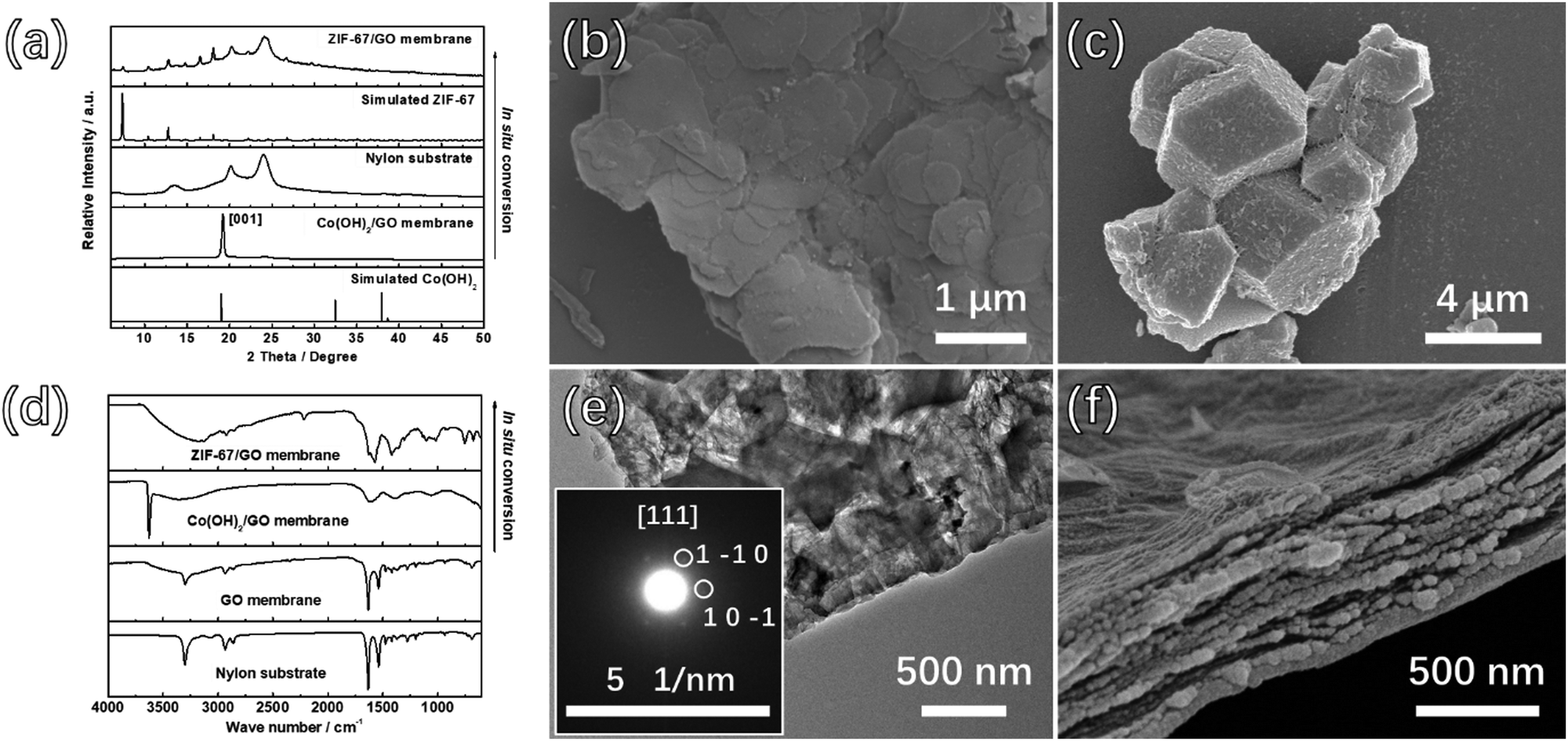 | ||
| Fig. 1 In situ conversion from Co(OH)2/GO to ZIF-67/GO sandwich membranes. (a and d) PXRD and FTIR spectra for the membranes before and after the conversion process. (b) SEM image of Co(OH)2 NS. (c) SEM image of the ZIF-67 converted from Co(OH)2 NS without GO. (e) TEM and (f) cross-section SEM images of the ZIF-67/GO membrane. | ||
The Co(OH)2/GO precursor membranes were prepared by vacuum filtration of different volumes of Co(OH)2/GO suspension onto the nylon substrates and the optimized ratio of Co(OH)2:GO was demonstrated to be 4:1 (Table S1, ESI†). Varied volumes of Co(OH)2/GO suspension (20 mL, 25 mL, 30 mL, 35 mL, and 40 mL) were applied to obtain the Co(OH)2/GO-x (where x denotes the consumed volume of the Co(OH)2/GO suspension) membranes with different thicknesses. The top-view and cross-section SEM images, as shown in Fig. S2 and S3 (ESI†) indicate the continuous surfaces and ultra-thin thicknesses of the membranes. The XRD results further demonstrated that Co(OH)2 was successfully filled between GO by the clear Co(OH)2 peaks for all membranes (Fig. S4, ESI†).
The 2-MIM solution was added to the surface of the membranes to conduct the conversion process before the precursor membranes were completely dry, forming adhesions between membranes and nylon substrates during the in situ transformation process. The conversion process was carried out at room temperature for 48 hours to obtain the final membranes. During the in situ transformation process, the membranes were adhered to the nylon substrates and were difficult to scrape from the substrates, suggesting a robust membrane product. The color of the 2-MIM solution changed to purple after the in situ conversion process, implying the release of Co2+ ions of from Co(OH)2 and the self-assembly of ZIF-67 from dissolved Co2+ and 2-MIM.
No Co(OH)2 peaks were present in the PXRD pattern and the peaks of ZIF-67 were observed as shown in Fig. 1a and Fig. S5a (ESI†), indicating the successful conversion from Co(OH)2 NS to ZIF-67. Furthermore, as shown in the inset of Fig. 1e, the interplanar spacing of the (1 −1 0) planes calculated from the SAED patterns was ∼1.163 nm, which is in agreement with the value obtained from the XRD pattern of ZIF-67, indicating the formation of the MOF. However, the PXRD pattern for the ZIF-67/GO-20 membrane prepared with the least precursor presents invisible peaks of ZIF-67, which may be attributed to the low content of MOFs. To prove this point, we prepared the membrane by directly mixing the ZIF-67 crystals and GO with the same ZIF-67/GO ratio of the ZIF-67/GO-20 membrane. The PXRD pattern of this membrane is shown in Fig. S5b (ESI†), and there is no obvious peak of ZIF-67 in the pattern. The conversion from Co(OH)2 to ZIF-67 can be further confirmed by the FTIR measurements (Fig. 1d, 2a, and Fig. S6, ESI†). After the transformation, the peaks at 750 and 1400 cm−1 appeared, attributed respectively to the out of plane vibration and stretching vibration of the imidazole ring related to ZIF-67. More importantly, the peaks at 1720 cm−1 for the C![[double bond, length as m-dash]](https://www.rsc.org/images/entities/char_e001.gif) O stretching vibration and 3405 cm−1 for the O–H stretching vibration from GO shifted to lower frequency at 1630 cm−1 and 3150 cm−1, respectively for ZIF-67/GO,49 while the peak for the C–N stretching vibrations shifted from 1376 cm−1 to 1353 cm−1, compared to that of pure ZIF-67. These are assigned to the formation of hydrogen bonds between different groups on GO and the ZIF-67.50
O stretching vibration and 3405 cm−1 for the O–H stretching vibration from GO shifted to lower frequency at 1630 cm−1 and 3150 cm−1, respectively for ZIF-67/GO,49 while the peak for the C–N stretching vibrations shifted from 1376 cm−1 to 1353 cm−1, compared to that of pure ZIF-67. These are assigned to the formation of hydrogen bonds between different groups on GO and the ZIF-67.50
The XPS tests were carried out to study the chemistry between GO and MOF as well (Fig. 2b–d). The N 1s spectrum of the ZIF-67/GO-40 membrane can be deconvoluted into two peaks, –C–N– (399.2 eV) present in pure ZIF-67 and a new peak at 400.3 eV. The peak at 400.3 eV is assigned to nitrogen atoms from 2-MIM bonded to the GO layer via the hydrogen bond,51 which is consistent with the FTIR results. On the other hand, O 1s component peaks shifted from 531.9 eV (CO) and 532.8 eV (O–CO, C–O–C) to 532.1 eV and 533.4 eV, respectively. These results showed an increased electron cloud density of C atoms and a decreased electron cloud density of O atoms, suggesting that the 2-MIM in ZIF-67 could form hydrogen bonds with the O atoms of GO.52,53 The bonding strength can prevent the interfacial micro-gaps and reduce the possibility of selectivity loss. In addition, the C 1s peaks of ZIF-67/GO membranes were deconvoluted into –C–OH (286.5 eV), –CC–/–C–C– (284.3 eV) and –CO (288.7 eV) from GO, and –CN (285.3 eV), –C–N (284.8 eV) originally in ZIF-67 (Fig. 2d and Table S2, ESI†). The enhanced intensity of CO (288.7 eV) was caused by the sealed CO2 in the membranes, which will be discussed below.
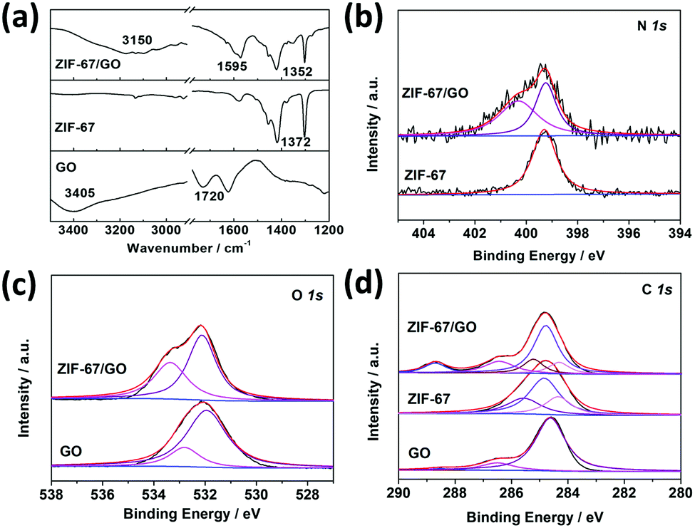 | ||
| Fig. 2 (a) FTIR spectra of GO, ZIF-67, and ZIF-67/GO. (b) N 1s, (c) O 1s, and (d) C 1s XPS spectra for GO, ZIF-67, and ZIF-67/GO. | ||
To check the actual loading amounts of ZIF-67 in converted membranes, the inductively coupled plasma emission spectrometer (ICP) characterization was carried out on the different membranes. The membranes were heated to ∼500 °C in the air then dissolved in acid to perform the ICP tests, and the results are summarized in Table S3 (ESI†). The ratios of ZIF-67/GO increased with the volume of filtration solution, while all the values were less than the initial mixing ratios. These results further confirmed the fact that during the transformation process, part of the cobalt source was converted into ZIF-67, while the other part was dissolved in the 2-MIM solution. ICP tests were also carried out on the reaction solution after the conversion for ZIF-67/GO-20 and ZIF-67/GO-40, and the results are shown in Table S4 (ESI†). Based on the coordination equilibrium, higher metal ion concentration in the 2-MIM solution of ZIF-67/GO-40 made the equilibrium shift in the direction of ZIF-67 formation, which resulted in the higher ZIF-67 ratio in the membranes.
Expectedly, the continuous and laminar ZIF-67/GO membrane structure was achieved by employing this in situ conversion strategy, thanks to the two-dimensional confinement effect served by GO layers. If the conversion process was carried out without GO, ZIF-67 crystals with the size of 3–4 μm were obtained (Fig. 1c). The ZIF-67/GO membranes with varied thicknesses of around 130, 250, 330, 400, and 500 nm, corresponding to ZIF-67/GO-20, 25, 30, 35 and 40, respectively, can be examined from the cross-section SEM images (Fig. S7 and S8, ESI†). It is obvious that the layered membranes were not burst open by converted ZIF-67 (Fig. S9, ESI†), indicating the small thickness of ZIF-67. Furthermore, as revealed by the EDS mapping of the precursor and converted membrane (Fig. 3), the cobalt element was dispersed uniformly in the GO matrix, suggesting that ZIF-67 was evenly formed from the Co(OH)2 precursor in the composite membranes. The AFM images, shown in Fig. S10 (ESI†), further illustrate that the thickness of the samples scraped from the ZIF-67/GO membranes were below 20 nm.
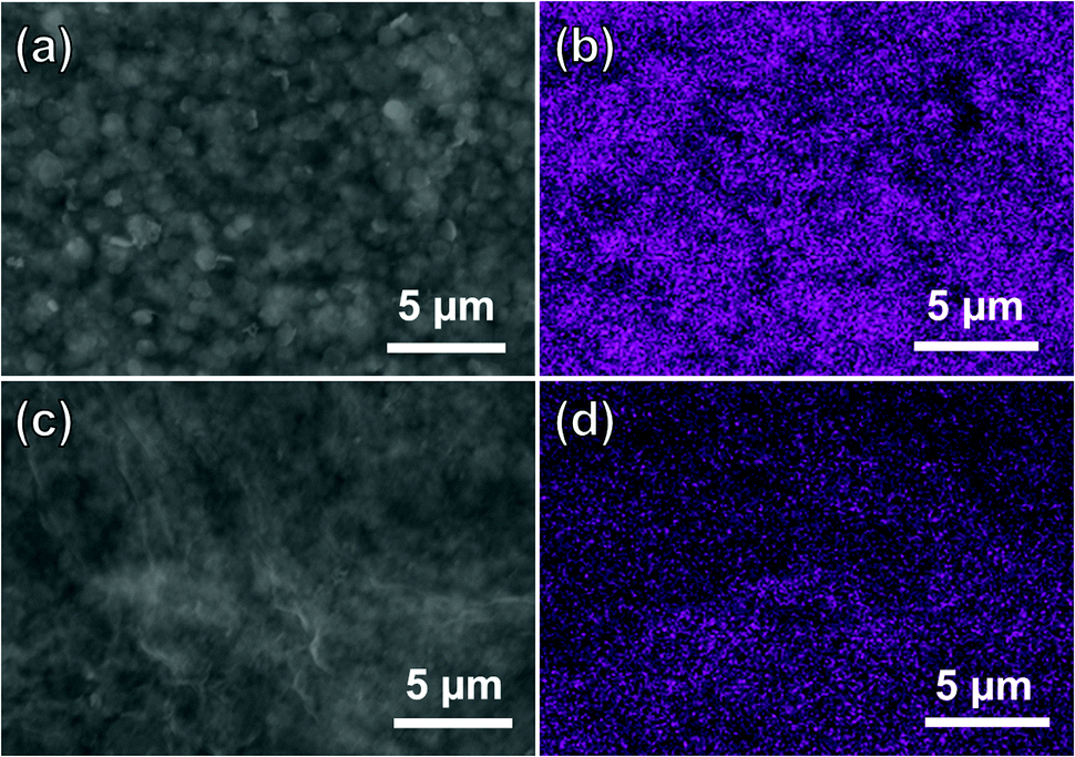 | ||
| Fig. 3 Top-view SEM and Co EDS mapping of (a and b) Co(OH)2/GO-40 and (c and d) ZIF-67/GO-40 membrane. | ||
To further study the two-dimensional confinement effect of GO layers during the conversion process, the Co(OH)2 powders and Co(OH)2/GO membranes after different conversion times (2 h, 8 h, 16 h, 36 h, and 48 h) were monitored by PXRD and SEM, and the results are summarized in Fig. S11 and S12 (ESI†). For the pure Co(OH)2 precursor, ZIF-67 crystals with the size of around 1 μm began to form on the surfaces of the precursors after 8 hours, as confirmed by the SEM image. After 36 hours, all Co(OH)2 was transformed into ZIF-67 crystals, which corresponds to the PXRD and FTIR results. Eventually, the ZIF-67 crystals reached 3–4 μm after 48 hours (Fig. S12j, ESI†). In contrast to the pure Co(OH)2 precursor, the XRD peaks corresponding to ZIF-67 were not observed in the Co(OH)2/GO membranes until 36 hours after the conversion began, and the wide peaks suggest the nanosized features of converted ZIF-67. The SEM images of the converted membranes (Fig. S12a–e, ESI†) presented no microcrystalline ZIF-67 on their tops, and the ZIF-67/GO membranes presented continuous and relatively smooth surfaces. The ZIF-67/GO-D membranes were prepared by directly mixing nano-sized ZIF-67 (referred to ZIF-67 NC) and GO for comparison. The loading amounts of ZIF-67 NC in ZIF-67/GO-D-20, 30 and 40 membranes were controlled according to the ratio in the respective ZIF-67/GO-x membranes. As revealed in Fig. S13 (ESI†), the size of ZIF-67 NC was around 400 nm, the composite membranes were not smooth, and the large size of ZIF-67 NC caused many defects in the membranes. These results suggest that the two-dimensional confinement of GO layers played a key role in maintaining the laminar morphology of the membranes.
There is one noticeable phenomenon from the ATR-FTIR results. It is interesting that a new peak at 2225 cm−1, ascribed to neither GO nor ZIF-67, appeared during the conversion process (Fig. 1d and 4a). Although this strong peak is quite similar to the nitrile peak, it is less possible that the C![[triple bond, length as m-dash]](https://www.rsc.org/images/entities/char_e002.gif) N bond can be formed under these moderate conditions. Therefore, the in situ temperature-dependent FTIR measurements were performed on the membrane samples to better understand this peak. A self-made in situ sample stage and temperature controlling system were employed for the in situ temperature-dependent FTIR measurements, and the results are shown in Fig. 4c and d. It is obvious that the 2225 cm−1 peak almost remained unchanged below 150 °C, although the slight drop in its intensity and small red-shift are detected, which can be ascribed to the heating effects. However, the intensity drastically decreased above 150 °C, while the wide band related to free CO2 grew simultaneously. For further illustrating the origin of this peak, the FTIR spectra of ZIF-67/GO membranes before and after annealing treatment in the vacuum oven at 150 °C for 12 hours were obtained (Fig. 4b). The strong 2225 cm−1 peak evidently weakened after annealing treatment, and the CO2 peak at 2340 cm−1 was not observed.60,61 Therefore, we can conclude that the 2225 cm−1 peak is ascribed to the CO2 molecules fixed in the membrane through hydrogen bonding interactions between CO2 and GO as well as CO2 and ZIF-67.62 The strong hydrogen bonding interactions shift the asymmetric stretching of CO2 from 2340 cm−1 to 2225 cm−1. In the ATR-FTIR results of the different membranes, it is clear that the sealed CO2 peaks decrease with the membrane thickness, implying that the CO2 is sealed within the membrane rather than adsorbed at the surfaces (Fig. S6b, ESI†). XPS results further support the existence of CO2 due to the stronger peak at 288.4 eV and 533.4 eV (Fig. 2d). It is noteworthy that this new interaction can be ascribed to the synergistic effects between ZIF-67 and GO through the in situ conversion process, since neither ZIF-67, GO nor ZIF-67/GO physical mixtures have such CO2 peaks in their FTIR spectra.
N bond can be formed under these moderate conditions. Therefore, the in situ temperature-dependent FTIR measurements were performed on the membrane samples to better understand this peak. A self-made in situ sample stage and temperature controlling system were employed for the in situ temperature-dependent FTIR measurements, and the results are shown in Fig. 4c and d. It is obvious that the 2225 cm−1 peak almost remained unchanged below 150 °C, although the slight drop in its intensity and small red-shift are detected, which can be ascribed to the heating effects. However, the intensity drastically decreased above 150 °C, while the wide band related to free CO2 grew simultaneously. For further illustrating the origin of this peak, the FTIR spectra of ZIF-67/GO membranes before and after annealing treatment in the vacuum oven at 150 °C for 12 hours were obtained (Fig. 4b). The strong 2225 cm−1 peak evidently weakened after annealing treatment, and the CO2 peak at 2340 cm−1 was not observed.60,61 Therefore, we can conclude that the 2225 cm−1 peak is ascribed to the CO2 molecules fixed in the membrane through hydrogen bonding interactions between CO2 and GO as well as CO2 and ZIF-67.62 The strong hydrogen bonding interactions shift the asymmetric stretching of CO2 from 2340 cm−1 to 2225 cm−1. In the ATR-FTIR results of the different membranes, it is clear that the sealed CO2 peaks decrease with the membrane thickness, implying that the CO2 is sealed within the membrane rather than adsorbed at the surfaces (Fig. S6b, ESI†). XPS results further support the existence of CO2 due to the stronger peak at 288.4 eV and 533.4 eV (Fig. 2d). It is noteworthy that this new interaction can be ascribed to the synergistic effects between ZIF-67 and GO through the in situ conversion process, since neither ZIF-67, GO nor ZIF-67/GO physical mixtures have such CO2 peaks in their FTIR spectra.
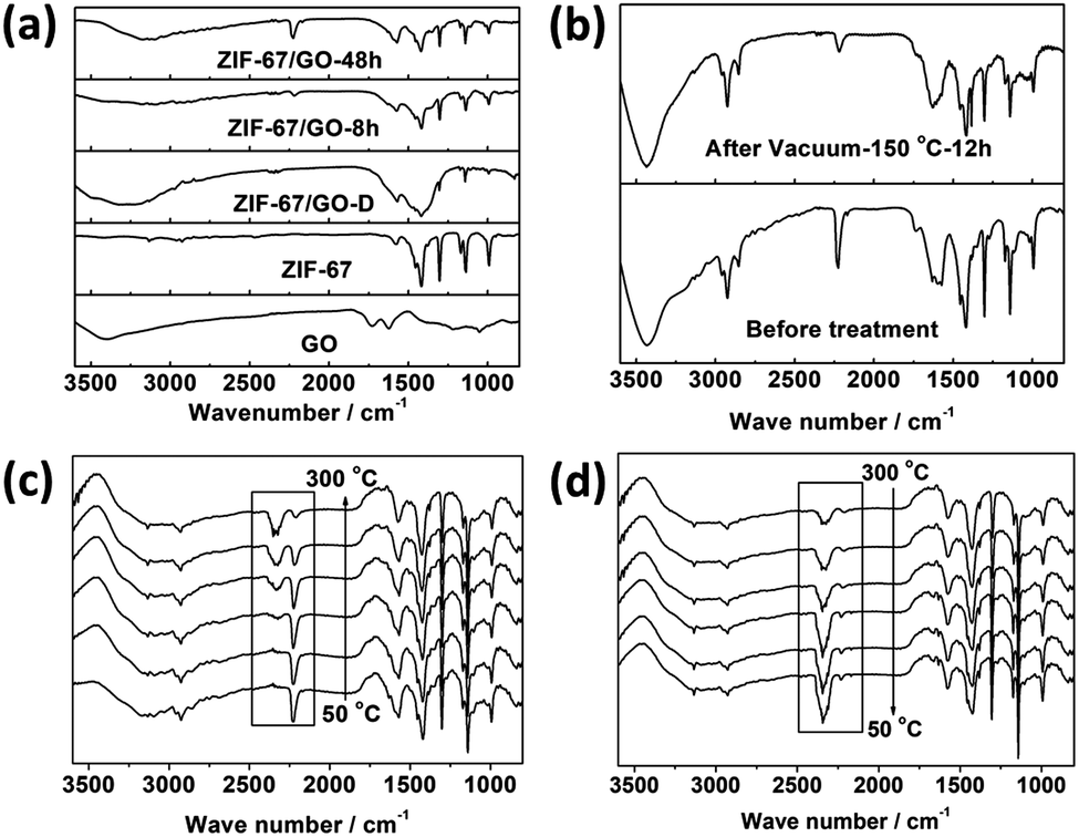 | ||
| Fig. 4 (a and b) Comparison of off situ FTIR spectrograms for different samples. (c and d) In situ temperature-dependent FTIR results of sample scraped from the ZIF-67/GO membrane. | ||
Gas sorption measurements of the fabricated membranes and pure GO were performed by physical gas adsorption. Calculated based on the N2 adsorption isomers at 77 K (Fig. S14a, ESI†), the BET surface area of ZIF-67/GO membranes was 540.8 m2 g−1, which was significantly increased compared with pristine GO (66.3 m2 g−1). These results could be attributed to the presence of ZIF-67 in the membrane that enhanced the free volume to facilitate the diffusion of gas molecules. The samples were evaluated on the H2 and CO2 adsorption properties after BET tests. It is interesting that the H2 and CO2 adsorption amounts of ZIF-67/GO-40 decrease significantly compared with pure GO at 298 K (Fig. S14b, ESI†). We examined the samples several times and had the same results. One possible reason is that the bound CO2 prevents the gas being adsorbed within the membranes and the gas was only adsorbed to the surfaces.
Gas separation performance of the sandwich membrane
As discussed above, the advantages of the homogeneous distribution of microporous fillers, suitable compatibility between fillers and matrix, and thin selective layers were achieved by the in situ conversion process under the two-dimensional confinement strategy, suggesting ZIF-67/GO membranes as a promising candidate for efficient light gases separation. The small window of ZIF-67 and the strong interaction between CO2 and interlayers of sandwich membranes imply the good hindering effects of the membrane on CO2 passage, while small H2 molecules with weak affinity can easily pass through. Therefore, the sandwich membrane is expected to possess enhanced H2/CO2 separation performance as compared with bare GO membranes.Single gas permeation tests were carried out on the ZIF-67/GO membranes, and the results are summarized in Fig. S15 (ESI†). The low single gas permeation of CO2 is due to the hybrid gas channels of the ZIF-67/GO membrane, the strong diffusion resistance associated with the narrow window of the membrane and the adsorption effects. In the ZIF-67/GO composite membrane, both of the flexible interspaces of GO and the small ZIF-67 framework channels contribute to the hybrid gas permeation system. The strongly adsorbed CO2 by ZIF-67, GO and their synergistic effects reduce its permeation rate in the single permeation tests. N2 can permeate through the interlayer pores of GO but would be blocked by the inserted ZIF-67, which is the reason N2 possesses higher permeance than CO2 but lower permeance than H2.63–65 Mixed gas (H2/CO2) separation studies were performed on the pure GO, Co(OH)2/GO, and ZIF-67/GO-x membranes at 25 °C (Fig. 5a). Compared with the pure GO membrane, the H2/CO2 selectivity of the ZIF-67/GO-40 sandwich membrane was increased by six-fold, from 9.3 ± 0.5 to 75 ± 4, and the permeance remained relatively high (H2 = 5922 ± 1000 GPU). This separation performance was investigated from five different membranes (Table S5, ESI†), proving the reproducibility of the membrane. The results demonstrated that the porous ZIF-67 fillers assembled in situ in the GO matrix were helpful in improving the gas separation performance.
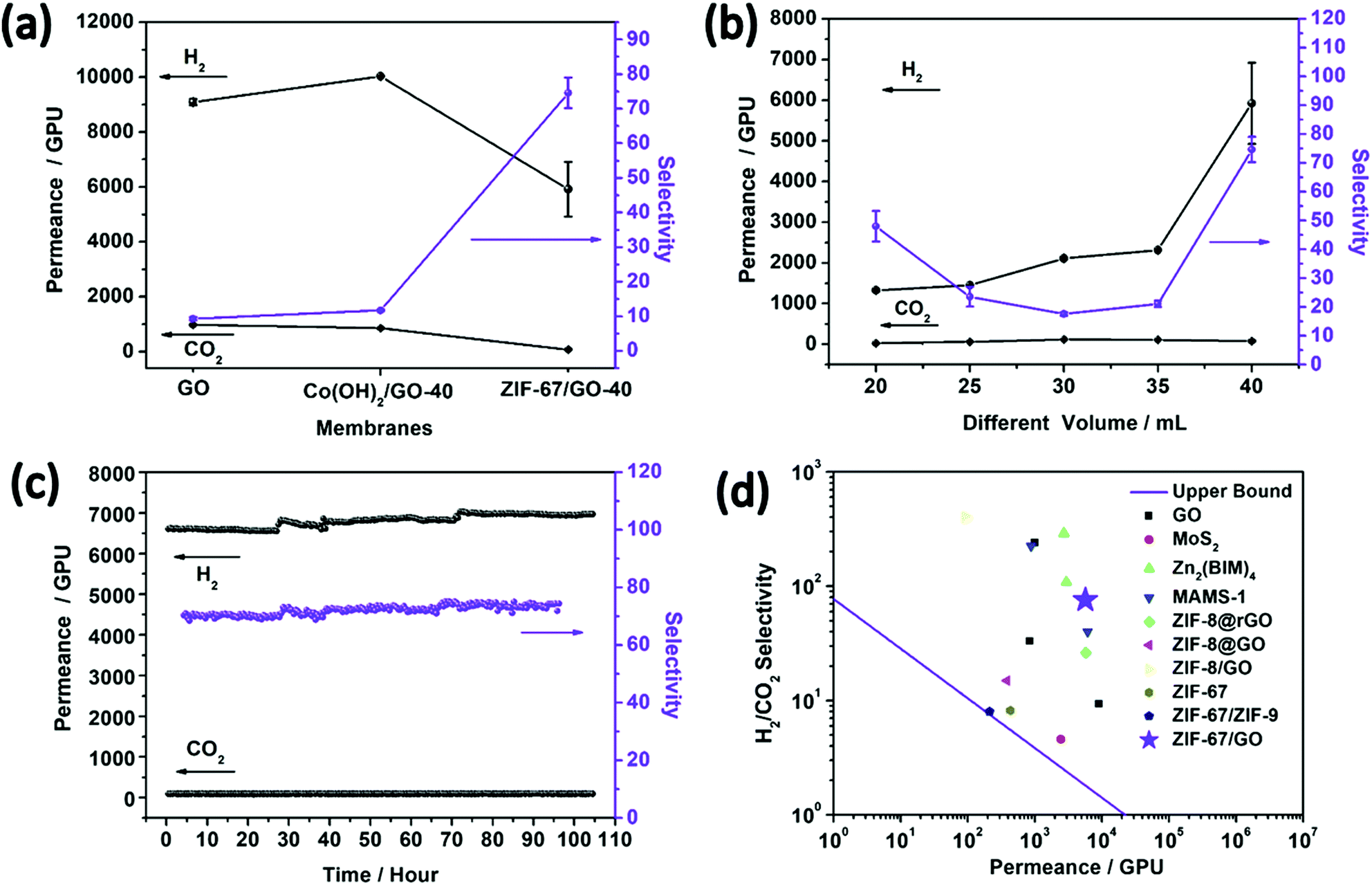 | ||
| Fig. 5 (a) H2/CO2 mixed gas separation performances on the GO membrane, Co(OH)2/GO-40 MMMs and ZIF-67/GO-40 composite membranes. (b) H2/CO2 mixed gas separation performances on the ZIF-67/GO composite membranes with different thicknesses at 25 °C. (c) The plot of H2/CO2 permeance and selectivity for the ZIF-67/GO-40 composite membrane versus test time. (d) H2/CO2 selectivity as a function of H2 permeability for the ZIF-67/GO-40 membrane compared with other 2D and ZIF-67 structure-based membranes reported in the literature1,5,13,32,54–58 (Table S6, ESI†). The upper bound lines of H2/CO2 for polymer membranes are plotted according to ref. 59, assuming a membrane thickness of 200 nm. | ||
The effects of the membrane thickness (or precursor solution volumes) on the separation properties were evaluated, and the separation performances of the membranes for each thickness were examined with two or more membranes and the same trend was obtained. As shown in Fig. 5b, the permeance of H2 presented an increasing trend with the increasing membrane thickness, while the H2/CO2 selectivity firstly decreased then increased. This phenomenon could be attributed to an integrated effect associated with the defects and thickness of the composite membranes. Involving ZIF-67 in GO expands the fractional free-volume (FFV) of the membrane and enhances gas permeance. However, it also brings defects that are detrimental to the separation effects. Therefore, ZIF-67/GO-30 has the poorer H2/CO2 selectivity compared with its thinner counterparts, possibly due to the larger amounts of defects. Fortunately, the H2/CO2 selectivity recovered with continuous increasing of the thickness. However, the defects can be covered by more layers in the thicker membranes, contributing to better H2/CO2 selectivity performances in ZIF-67/GO-35 and ZIF-67/GO-40. We also attempted to fabricate the ZIF-67/GO-50 membrane to further evaluate the thickness effects; however, the membrane became too thick to stick to the nylon support.
To study the temperature effect on gas permeance, mixed gas separation tests were carried out from 25 °C to 150 °C on the ZIF-67/GO-40 membrane (Fig. S16, ESI†). At higher temperature, a more activated CO2 diffusion resulted from the weakened adsorption of CO2 by GO and ZIF-67, leading to a decrease in H2/CO2 selectivity. Similar phenomena have also been reported by other groups for 2D membranes.46,47,66 The gas permeance increased substantially as the separation temperature increased, and the slightly decreased hydrogen permeability with temperature from 60 to 100 °C may be caused by the breaking of hydrogen bonds between CO2 and the ZIF-67/GO membrane at high temperature, resulting in the larger amount of CO2 that blocks the diffusion of H2. The cycling performance of the ZIF-67/GO-40 membrane was evaluated by the continuous H2/CO2 permeance testing up to 120 hours. No noticeable performance loss was detected (Fig. 5c), indicating its excellent stability for long-term continuous operations. The XRD and SEM characterizations were carried out on the ZIF-67/GO-40 membranes after a long time and high-temperature separation tests, and the results (Fig. S17, ESI†) indicated that the structure and morphology of ZIF-67/GO-40 membranes were well maintained after a series of gas separation tests. As shown in Fig. 5d and Table S6 (ESI†), compared with other 2D membranes and ZIF-67 based membranes, the ZIF-67/GO sandwich membranes in this work showed a balance of permeance and selectivity and surpassed the 2008 upper bound line of polymer membranes. Therefore, the two-dimensional confinement strategy of involving MOF fillers into GO was proved to be effective to improve gas separation performances.
For the practical application of pre-combustion CO2 capture, the efficient H2/CO2 separation under real conditions (high temperature above 200 °C, feed gas with steam) is of the highest interest. Evaluating the H2/CO2 separation performance at low temperature may guide the selection of promising candidates with high permeance and selectivity from the new materials; however, it is still challenging to apply the GO or MOF based membranes in the practical separation conditions. For the GO-based membranes, hydration increases the GO spacing to −0.9 nm,8 and CO2 shows a higher solubility coefficient in water than any other gas.67 Hydrothermal stability is one of the weaknesses of the MOF based polycrystalline membranes applied in the practical separation. Favorably, the ZIF-67/GO composite membrane can overcome the cracks and inter-crystal defects of the polycrystalline membranes56 and the hierarchical structures or multiple transport mechanisms that may result in the water-facilitated CO2 capture property.68 To evaluate the separation performance at high temperature with water vapor, the ZIF-67/GO-40 membrane was heated to 150 °C (the nylon substrates become brittle at 200 °C) and exposed to an equimolar H2/CO2 feed containing ∼4 mol% steam. The membrane exhibited a H2 permeance of 3654 ± 252 GPU and a H2/CO2 selectivity of 31 ± 3, which are attractive values for the pre-combustion capture.69 The significantly decreased gas permeance was due to the partial blockage of the membrane pores,70 and a more decreased CO2 permeance was caused by the competitive sorption in the ZIF-67 micropores.71 According to the competitive sorption theory, the presence of water vapor affects the permeation of high-affinity components to a greater extent, compared with the permeation of low-affinity components,72 resulting in the increased selectivity compared with the membrane property tested under dry conditions. This separation performance at high temperature with steam further indicates that this ZIF-67/GO-40 membrane is a promising candidate for the practical application of pre-combustion CO2 capture.
Conclusions
Laminar sandwich membranes of ZIF-67/GO were obtained from Co(OH)2/GO precursors through a two-dimensional confinement strategy. The interaction between ZIF-67 and GO was formed during the in situ conversion process. The ultra-thin membranes with evenly dispersed ZIF-67 showed the significantly enhanced gas separation performance of the H2/CO2 mixture compared with the pristine GO membrane (H2 permeance of 5922 ± 1000 GPU and H2/CO2 selectivity of 75 ± 4) at 25 °C. Furthermore, the composite membrane is stable at 150 °C with the feed gas containing steam, and possesses a H2 permeance of 3654 ± 252 GPU and a H2/CO2 selectivity of 31 ± 3. Thanks to the diverse structures of the MOFs and the simple preparation process, the MOF/GO sandwich membranes prepared via the two-dimensional confinement strategy can be considered as potential materials for energy-efficient molecular separations. However, the understanding of the mechanistic aspects of this conversion process to MOFs is still unclear. Some advanced operando characterization technologies established in the nanoscience field can be readily applied to study the time-resolved dynamics issues in this system, which will be investigated in our future work.Conflicts of interest
There are no conflicts to declare.Acknowledgements
This work was supported by National Natural Science Foundation of China (21501198, 21601205, 21771193, and 21571187), Taishan Scholar Foundation (ts201511019) and the Fundamental Research Funds for the Central Universities (18CX02047A, 18CX07001A).Notes and references
- Y. L. Y. Peng, Y. Ban, H. Jin, W. Jiao, X. Liu and W. Yang, Science, 2014, 346, 1356–1359 CrossRef PubMed.
- M. Y. Jeon, D. Kim, P. Kumar, P. S. Lee, N. Rangnekar, P. Bai, M. Shete, B. Elyassi, H. S. Lee, K. Narasimharao, S. N. Basahel, S. Al-Thabaiti, W. Xu, H. J. Cho, E. O. Fetisov, R. Thyagarajan, R. F. DeJaco, W. Fan, K. A. Mkhoyan, J. I. Siepmann and M. Tsapatsis, Nature, 2017, 543, 690–694 CrossRef PubMed.
- W. J. Koros and C. Zhang, Nat. Mater., 2017, 16, 289–297 CrossRef PubMed.
- H. B. Park, J. Kamcev, L. M. Robeson, M. Elimelech and B. D. Freeman, Science, 2017, 356, eaab0530 CrossRef PubMed.
- X. Wang, C. Chi, K. Zhang, Y. Qian, K. M. Gupta, Z. Kang, J. Jiang and D. Zhao, Nat. Commun., 2017, 8, 14460 CrossRef PubMed.
- Y. Liu, Y. Ban and W. Yang, Adv. Mater., 2017, 29, 1606949 CrossRef PubMed.
- R. K. Joshi, P. Carbone, F. C. Wang, V. G. Kravets, Y. Su, I. V. Grigorieva, H. A. Wu, A. K. Geim and R. R. Nair, Science, 2014, 343, 752–754 CrossRef PubMed.
- B. Mi, Science, 2014, 343, 740–742 CrossRef PubMed.
- G. Liu, W. Jin and N. Xu, Chem. Soc. Rev., 2015, 44, 5016–5030 RSC.
- L. Chen, G. Shi, J. Shen, B. Peng, B. Zhang, Y. Wang, F. Bian, J. Wang, D. Li, Z. Qian, G. Xu, G. Liu, J. Zeng, L. Zhang, Y. Yang, G. Zhou, M. Wu, W. Jin, J. Li and H. Fang, Nature, 2017, 550, 380–383 CrossRef PubMed.
- J. Abraham, K. S. Vasu, C. D. Williams, K. Gopinadhan, Y. Su, C. T. Cherian, J. Dix, E. Prestat, S. J. Haigh, I. V. Grigorieva, P. Carbone, A. K. Geim and R. R. Nair, Nat. Nanotechnol., 2017, 12, 546–550 CrossRef PubMed.
- M. Hu and B. Mi, Environ. Sci. Technol., 2013, 47, 3715–3723 CrossRef PubMed.
- J. Shen, G. Liu, K. Huang, Z. Chu, W. Jin and N. Xu, ACS Nano, 2016, 10, 3398–3409 CrossRef PubMed.
- K. Goh, W. Jiang, H. E. Karahan, S. Zhai, L. Wei, D. Yu, A. G. Fane, R. Wang and Y. Chen, Adv. Funct. Mater., 2015, 25, 7348–7359 CrossRef.
- W.-S. Hung, C.-H. Tsou, M. De Guzman, Q.-F. An, Y.-L. Liu, Y.-M. Zhang, C.-C. Hu, K.-R. Lee and J.-Y. Lai, Chem. Mater., 2014, 26, 2983–2990 CrossRef.
- H. Huang, Z. Song, N. Wei, L. Shi, Y. Mao, Y. Ying, L. Sun, Z. Xu and X. Peng, Nat. Commun., 2013, 4, 2979 CrossRef PubMed.
- G. Liu, W. Jin and N. Xu, Angew. Chem., Int. Ed., 2016, 55, 13384–13397 CrossRef PubMed.
- P. Bernardo, E. Drioli and G. Golemme, Ind. Eng. Chem. Res., 2009, 48, 4638–4663 CrossRef.
- J. Dechnik, J. Gascon, C. J. Doonan, C. Janiak and C. J. Sumby, Angew. Chem., Int. Ed., 2017, 56, 2–21 CrossRef PubMed.
- J. Dechnik, C. J. Sumby and C. Janiak, Cryst. Growth Des., 2017, 17, 4467–4488 CrossRef.
- Z. Kang, Y. Peng, Z. Hu, Y. Qian, C. Chi, L. Y. Yeo, L. Tee and D. Zhao, J. Mater. Chem. A, 2015, 3, 20801–20810 RSC.
- Z. Hu, Z. Kang, Y. Qian, Y. Peng, X. Wang, C. Chi and D. Zhao, Ind. Eng. Chem. Res., 2016, 55, 7933–7940 CrossRef.
- T. Rodenas, M. van Dalen, E. García-Pérez, P. Serra-Crespo, B. Zornoza, F. Kapteijn and J. Gascon, Adv. Funct. Mater., 2014, 24, 249–256 CrossRef.
- L. H. Wee, Y. Li, K. Zhang, P. Davit, S. Bordiga, J. Jiang, I. F. J. Vankelecom and J. A. Martens, Adv. Funct. Mater., 2015, 25, 516–525 CrossRef.
- J. R. Li, R. J. Kuppler and H. C. Zhou, Chem. Soc. Rev., 2009, 38, 1477–1504 RSC.
- H. Furukawa, K. E. Cordova, M. O'Keeffe and O. M. Yaghi, Science, 2013, 341, 1230444 CrossRef PubMed.
- S. Qiu, M. Xue and G. Zhu, Chem. Soc. Rev., 2014, 43, 6116–6140 RSC.
- Z. Kang, L. Fan and D. Sun, J. Mater. Chem. A, 2017, 5, 10073–10091 RSC.
- F. Zhang, X. Zou, X. Gao, S. Fan, F. Sun, H. Ren and G. Zhu, Adv. Funct. Mater., 2012, 22, 3583–3590 CrossRef.
- X. Liu, C. Wang, B. Wang and K. Li, Adv. Funct. Mater., 2017, 27, 1604311 CrossRef.
- K. Guan, D. Zhao, M. Zhang, J. Shen, G. Zhou, G. Liu and W. Jin, J. Membr. Sci., 2017, 542, 41–51 CrossRef.
- W. Li, Y. Zhang, P. Su, Z. Xu, G. Zhang, C. Shen and Q. Meng, J. Mater. Chem. A, 2016, 4, 18747–18752 RSC.
- M. Jia, Y. Feng, S. Liu, J. Qiu and J. Yao, J. Membr. Sci., 2017, 539, 172–177 CrossRef.
- J. Wang, Y. Wang, Y. Zhang, A. Uliana, J. Zhu, J. Liu and B. Van der Bruggen, ACS Appl. Mater. Interfaces, 2016, 8, 25508–25519 CrossRef PubMed.
- Y. Ying, D. Liu, W. Zhang, J. Ma, H. Huang, Q. Yang and C. Zhong, ACS Appl. Mater. Interfaces, 2017, 9, 1710–1718 CrossRef PubMed.
- H. Yang, N. Wang, L. Wang, H.-X. Liu, Q.-F. An and S. Ji, J. Membr. Sci., 2018, 545, 158–166 CrossRef.
- H. Yin, A. Khosravi, L. O’Connor, A. Q. Tagaban, L. Wilson, B. Houck, Q. Liu and M. L. Lind, Ind. Eng. Chem. Res., 2017, 56, 9167–9176 CrossRef.
- X.-L. Liu, Y.-S. Li, G.-Q. Zhu, Y.-J. Ban, L.-Y. Xu and W.-S. Yang, Angew. Chem., Int. Ed., 2011, 50, 10636–10639 CrossRef PubMed.
- R. Zhang, S. Ji, N. Wang, L. Wang, G. Zhang and J. R. Li, Angew. Chem., Int. Ed. Engl., 2014, 53, 9775–9779 CrossRef PubMed.
- X. Liu, H. Jin, Y. Li, H. Bux, Z. Hu, Y. Ban and W. Yang, J. Membr. Sci., 2013, 428, 498–506 CrossRef.
- Y. Mao, J. Li, W. Cao, Y. Ying, P. Hu, Y. Liu, L. Sun, H. Wang, C. Jin and X. Peng, Nat. Commun., 2014, 5, 5532 CrossRef PubMed.
- G. Zhan and H. C. Zeng, Adv. Funct. Mater., 2016, 26, 3268–3281 CrossRef.
- K. Shen, L. Zhang, X. Chen, L. Liu, D. Zhang, Y. Han, J. Chen, J. Long, R. Luque, Y. Li and B. Chen, Science, 2018, 359, 206–210 CrossRef PubMed.
- Z. Chen, B. Holmberg, W. Li, X. Wang, W. Deng, R. Munoz and Y. Yan, Chem. Mater., 2006, 18, 5669–5675 CrossRef.
- P. R. H. P. Rao and M. Matsukata, Chem. Commun., 1996, 1441–1442 RSC.
- Y. Peng, Y. Li, Y. Ban, H. Jin, W. Jiao, X. Liu and W. Yang, Science, 2014, 346, 1356–1359 CrossRef PubMed.
- H. Li, Z. Song, X. Zhang, Y. Huang, S. Li, Y. Mao, H. J. Ploehn, Y. Bao and M. Yu, Science, 2013, 342, 95–98 CrossRef PubMed.
- R. Banerjee, A. Phan, B. Wang, C. Knobler, H. Furukawa, M. O'Keeffe and O. M. Yaghi, Science, 2008, 319, 939–943 CrossRef PubMed.
- J. Han, Y. Shen and W. Feng, Nanoscale, 2016, 8, 14139–14145 RSC.
- J. Shen, G. Liu, K. Huang, W. Jin, K. R. Lee and N. Xu, Angew. Chem., Int. Ed. Engl., 2015, 54, 578–582 Search PubMed.
- Y. Matsuo, Y. Nishino, T. Fukutsuka and Y. Sugie, Carbon, 2007, 45, 1384–1390 CrossRef.
- N. I. Kovtyukhova, T. E. Mallouk, L. Pan and E. C. Dickey, J. Am. Chem. Soc., 2003, 125, 9761–9769 CrossRef PubMed.
- M. Yoonessi, Y. Shi, D. A. Scheiman, M. Lebron-Colon, D. M. Tigelaar, R. A. Weiss and M. A. Meador, ACS Nano, 2012, 6, 7644–7655 CrossRef PubMed.
- C. Chi, X. Wang, Y. Peng, Y. Qian, Z. Hu, J. Dong and D. Zhao, Chem. Mater., 2016, 28, 2921–2927 CrossRef.
- D. Wang, Z. Wang, L. Wang, L. Hu and J. Jin, Nanoscale, 2015, 7, 17649–17652 RSC.
- A. Huang, Q. Liu, N. Wang, Y. Zhu and J. Caro, J. Am. Chem. Soc., 2014, 136, 14686–14689 CrossRef PubMed.
- X. Wang, C. Chi, J. Tao, Y. Peng, S. Ying, Y. Qian, J. Dong, Z. Hu, Y. Gu and D. Zhao, Chem. Commun., 2016, 52, 8087–8090 RSC.
- F. Cacho-Bailo, I. Matito-Martos, J. Perez-Carbajo, M. Etxeberria-Benavides, O. Karvan, V. Sebastian, S. Calero, C. Tellez and J. Coronas, Chem. Sci., 2017, 8, 325–333 RSC.
- L. M. Robeson, J. Membr. Sci., 2008, 320, 390–400 CrossRef.
- S. U. Rege and R. T. Yang, Chem. Eng. Sci., 2001, 56, 3781–3796 CrossRef.
- K. Roztocki, M. Lupa, M. Hodorowicz, I. Senkovska, S. Kaskel and D. Matoga, CrystEngComm, 2018, 20, 2841–2849 RSC.
- X. Wang, V. Schwartz, J. C. Clark, X. Ma, S. H. Overbury, X. Xu and C. Song, J. Phys. Chem. C, 2009, 113, 7260–7268 CrossRef.
- G. Xu, J. Yao, K. Wang, L. He, P. A. Webley, C.-s. Chen and H. Wang, J. Membr. Sci., 2011, 385-386, 187–193 CrossRef.
- E. Favre, D. Roizard, R. Bounaceur and W. J. Koros, Ind. Eng. Chem. Res., 2009, 48, 3700–3701 CrossRef.
- E. Jeon, S.-Y. Moon, J.-S. Bae and J.-W. Park, Angew. Chem., Int. Ed., 2016, 128, 1340–1345 CrossRef.
- L. Ding, Y. Wei, L. Li, T. Zhang, H. Wang, J. Xue, L. X. Ding, S. Wang, J. Caro and Y. Gogotsi, Nat. Commun., 2018, 9, 155 CrossRef PubMed.
- H. W. Kim, H. W. Yoon, S.-M. Yoon, B. M. Yoo, B. K. Ahn, Y. H. Cho, H. J. Shin, H. Yang, U. Paik, S. Kwon, J.-Y. Choi and H. B. Park, Science, 2013, 342, 91–95 CrossRef PubMed.
- J. Wang, S. Wang, Q. Xin and Y. Li, J. Mater. Chem. A, 2017, 5, 6794–6816 RSC.
- M. Galizia, W. S. Chi, Z. P. Smith, T. C. Merkel, R. W. Baker and B. D. Freeman, Macromolecules, 2017, 50, 7809–7843 CrossRef.
- J. Lindmark and J. Hedlund, J. Mater. Chem., 2010, 20, 2219–2225 RSC.
- H. Huang, W. Zhang, D. Liu and C. Zhong, Ind. Eng. Chem. Res., 2012, 51, 10031–10038 CrossRef.
- M. Pourafshari Chenar, M. Soltanieh, T. Matsuura, A. Tabe-Mohammadi and K. C. Khulbe, J. Membr. Sci., 2006, 285, 265–271 CrossRef.
Footnotes |
| † Electronic supplementary information (ESI) available. See DOI: 10.1039/c8qm00351c |
| ‡ These authors contribute equally to this work. |
| This journal is © the Partner Organisations 2018 |