Mo-Triggered amorphous Ni3S2 nanosheets as efficient and durable electrocatalysts for water splitting†
Haoxuan
Zhang
a,
Hao
Jiang
 *a,
Yanjie
Hu
 a,
Petr
Saha
b and
Chunzhong
Li
 *a
*a
aKey Laboratory for Ultrafine Materials of Ministry of Education & School of Materials Science and Engineering, East China University of Science and Technology, Shanghai 200237, China. E-mail: jianghao@ecust.edu.cn; czli@ecust.edu.cn
bCentre of Polymer Systems, University Institute, Tomas Bata University in Zlin, Trida T. Bati 5678, 760 01 Zlin, Czech Republic
First published on 14th May 2018
Abstract
Exploring efficient non-noble materials as hydrogen evolution reaction (HER) and oxygen evolution reaction (OER) bifunctional electrocatalysts is of great importance for overall water splitting. Herein, we report a low-temperature and rapid synthesis of Mo-triggered amorphous Ni3S2 nanosheets as such dual-function electrocatalysts for the first time by a simple solid-phase melting strategy. It is found that Mo engineering can not only dramatically enhance the adsorption ability of Ni active sites to the active intermediates of HER, but also generate more targeted intermediates for OER. The resulting a-Mo–Ni3S2 catalysts demonstrate exceptionally high HER/OER activity and stability in alkaline media, outperforming the baseline commercial noble-metal (Pt, IrO2 and RuO2) and other reported advanced electrocatalysts to date. A two-electrode electrolyzer assembled using the a-Mo–Ni3S2 electrocatalysts can afford a current density of 1000 mA cm−2 at a voltage of only 1.97 V which is stable for over 300 h. This work provides a feasible tactic to develop efficient and durable bifunctional electrocatalysts by engineering on surfaces and nanostructures.
Introduction
Producing hydrogen by water electrolysis can effectively integrate renewable energy such as solar energy and wind energy to truly realize sustainable utilization of clean energy.1–4 The development of this technique has been greatly limited by the high overpotential of the cathodic hydrogen evolution reaction (HER) and anodic oxygen evolution reaction (OER). Although noble metal catalysts (e.g. Pt, IrO2 and RuO2) can remarkably reduce reaction overpotentials, low abundance and high cost severely restrict their large-scale application.5,6 Therefore, it is indispensable to exploit highly active and low-cost non-precious metal electrocatalysts. And meanwhile, developing dual-function electrocatalysts for both HER/OER half-reactions is of even greater importance to further facilitate water splitting.7–9 It has been reported that the rich Ni–S and Ni–Ni bonds of Ni3S2 can not only dramatically improve the key OER active intermediate (OOH*) adsorption ability in alkaline media, but also accelerate the charge transfer in the bulk.10,11 These advantages render it an excellent OER electrocatalyst. However, the corresponding Ni active site has weak adsorption ability to key intermediates (OH−) of HER, resulting in sluggish kinetics of the rate-determining Volmer step (H2O + e− + * → H* + OH−) in the hydrogen evolution process.12,13Balancing the ability of the active sites to adsorb/desorb the key intermediate (OH−) for HER by tailoring the surface electronic structure of catalysts has been recognized as the most effective tactic to boost HER kinetics in alkaline media.14,15 Both theoretical and experimental studies have found that introducing free electron-enriched metal heteroatoms can increase the density of states around the Femi level of electrocatalysts and promote the separation of positive and negative charges at the interface.16,17 The finding is very favorable for exposing more active sites and regulating their adsorption ability to the key intermediates.18 Nevertheless, metal doping methods generally involve a high temperature treatment, easily causing precipitation and agglomeration of heteroatoms.19,20 On the other hand, compared with crystalline materials, amorphous structures are rich in unsaturated chemical bonds and defect sites, which can provide additional active sites and further improve the adsorption of active intermediates at the electrode/electrolyte interface.21,22 However, it is very difficult to simultaneously implement metal doping and amorphization of electrocatalysts.
Herein, we report a low-temperature and rapid synthesis of Mo-doped amorphous Ni3S2 electrocatalysts for the first time by means of a solid-phase melting strategy. The crystal structure and surface chemical state analyses indicate that Mo doping converts Ni3S2 from heazlewoodite into an amorphous phase, which significantly enhances the adsorption ability of Ni active sites to the active intermediates of HER. Meanwhile, it also promotes the generation of more targeted intermediates of OER. The resulting a-Mo–Ni3S2 catalysts demonstrate exceptionally high HER/OER activity and stability in alkaline media, outperforming the baseline commercial noble-metal (Pt, IrO2 and RuO2) and other advanced catalysts reported to date. Specifically, the a-Mo–Ni3S2 catalysts exhibit ultralow overpotentials (η) of 74 and 165 mV at 10 and 100 mA cm−2 for HER. The turnover frequency (TOF) is 6.39 s−1 at an overpotential of 150 mV, which is about four times higher than that of crystalline Ni3S2. Meanwhile, an overpotential of 276 mV at 100 mA cm−2 is attained for OER. A two-electrode electrolyzer assembled using the a-Mo–Ni3S2 electrocatalysts can afford a current density of 1000 mA cm−2 at a voltage of only 1.97 V which is stable for over 300 h.
Results and discussion
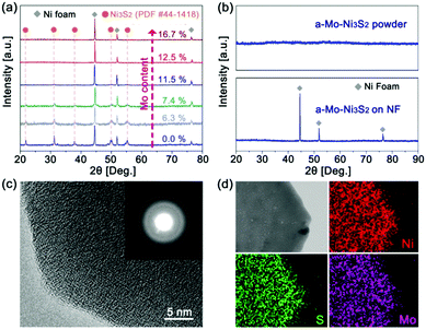
Mo-Doped amorphous Ni3S2 electrocatalysts have been synthesized on nickel foam by a low-temperature and rapid solid-phase melting strategy, in which the Ni foam was directly embedded in the precursor powders (CH3CSNH2 and Na2MoO4) at 220 °C for 40 minutes. The digital photographs (Fig. S1, ESI†) display an obvious colour change from gray to black. It is found that Mo content in products plays an important role in generating the amorphous structure, which can be easily controlled by changing the amount of Na2MoO4. Fig. 1a is the X-ray diffraction (XRD) patterns of the Ni3S2 samples with different Mo contents based on the inductively coupled plasma mass spectrometry (ICP-MS) results. Without the addition of Mo, the products show strong diffractive peaks of crystalline Ni3S2 (labelled as c-Ni3S2) with a bulk morphology (Fig. S2, ESI†). These diffractive peaks gradually weaken with the increase of Mo content and then totally disappear until the Mo content reaches 12.5 at%, implying the formation of the amorphous structure (labelled as a-Mo–Ni3S2). The fact has been further verified by the XRD pattern of the corresponding powder sample scraped from the Ni foam substrate (Fig. 1b). The a-Mo–Ni3S2 sample also seems to show a bulk morphology with a layer-like nanostructure (Fig. S3, ESI†), which is firmly covered on the Ni foam surface. The transmission electron microscopy (TEM) image in Fig. S4 (ESI†) gives a large nanosheet. The two-dimensional (2D) feature is expected to expose more electrocatalytic active sites. The high-resolution TEM image (Fig. 1c) shows the absence of a crystal lattice fringe, further confirming the amorphous feature, which has also been evidenced by the diffused rings in the selected area electron diffraction (SAED) pattern. Fig. 1d gives the homogeneous Ni, Mo and S elemental distribution in a-Mo–Ni3S2 nanosheets.The chemical state and composition of the a-Mo–Ni3S2 nanosheets have been characterized by X-ray photoelectron spectroscopy (XPS) and Raman spectroscopy. In Fig. 2a, the Ni 2p3/2 region can be fitted into three characteristic peaks at 855.9, 853.9 and 853.1 eV corresponding to Ni–OH, Ni–O and Ni–S bonds, respectively,23,24 and a satellite peak at 861.1 eV. For the S 2p region (Fig. 2b), the two peaks at 163.5 and 164.7 eV are attributed to S–Ni bonds while another two peaks at 161.8 and 164.3 eV belong to S–Mo bonds.25,26 A weak S–O bond appears at 168.3 eV, mainly due to the adsorption of oxygen species in air.27 In Fig. 2c, the S 2s region consists of two peaks at 227.9 and 228.4 eV corresponding to S–Mo and S–Ni bonds. The Mo 3d region shows two peaks at 232.5 and 235.7 eV, revealing that Mo is in the Mo6+ oxidation state.28 Moreover, the Raman spectrum (Fig. 2d) exhibits peaks at 272.4, 342.9, 480.0 and 557.8 cm−1 corresponding to the Ni–S bond while 723.8, 818.9, 886.4 and 945.8 cm−1 for the formation of the Ni–Mo bond.29,30 These results indicate that Mo atoms have been successfully doped into Ni3S2 by the way of chemical bonding.
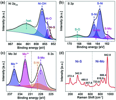 | ||
| Fig. 2 XPS spectra of (a) Ni 2p3/2, (b) S 2p, (c) Mo 3d/S 2s regions, and (d) Raman spectrum of the a-Mo–Ni3S2 nanosheets. | ||
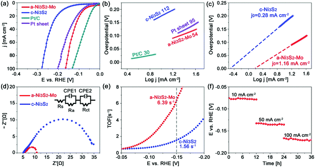
The a-Mo–Ni3S2 nanosheets are firstly evaluated as HER electrocatalysts in alkaline media by a standard three-electrode system with a saturated Ag/AgCl reference electrode and a graphite counter electrode, respectively. As shown in Fig. 3a, they exhibit ultralow overpotentials of 74 and 165 mV to obtain 10 and 100 mA cm−2, respectively, which are much lower than those of c-Ni3S2 (η10 = 176, η100 = 280 mV) and Pt sheet (η10 = 85, η100 = 204 mV). Such low overpotentials outperform the baseline commercial noble metals (Pt, IrO2 and RuO2). In a very recent work, Zhang et al. reported an advanced Ni1−xCoxSe2 mesoporous nanosheet network electrocatalyst by topological transformation and subsequent acid etching, which required a relatively high overpotential of 85 mV to generate 10 mA cm−2.31 Some representative works in the literature are summarized in Table S1 (ESI†). The Tafel slope (Fig. 3b) of a-Mo–Ni3S2 is 54 mV dec−1, which is more than twice as low as that of c-Ni3S2 (112 mV dec−1) and close to that of the commercial Pt/C electrocatalyst, indicating reinforced HER kinetics dominated by the Volmer–Heyrovsky mechanism. This feature can also be evidenced by the higher exchange current density (j0) of a-Mo–Ni3S2 (1.16 mA cm−2) in comparison to c-Ni3S2 (0.28 mA cm−2), as shown in Fig. 3c. Furthermore, the a-Mo–Ni3S2 electrocatalysts give a markedly lower charge-transfer resistance (∼6.0 Ω) than the c-Ni3S2 (∼30.0 Ω) (Fig. 3d), also indicating the improved HER kinetics. The turnover frequency (TOF) of a-Mo–Ni3S2 catalysts is calculated to be 6.39 s−1 according to a CV method (Fig. S5, ESI†),32 four times higher than that of c-Ni3S2 (1.56 s−1), as shown in Fig. 3e, exhibiting the enhanced intrinsic HER activity. In addition to catalytic activity, stability is another factor to be considered for sustainable energy conversion. Fig. 3f is the chronopotentiometry (CP) plots of a-Mo–Ni3S2 catalysts, demonstrating excellent stability with negligible potential change even after 36 h CP measurement at 10, 50 and 100 mA cm−2, respectively. The amorphous a-Mo–Ni3S2 electrocatalyst has been well-maintained after CP evaluation (Fig. S6, ESI†), implying the outstanding durability for HER.
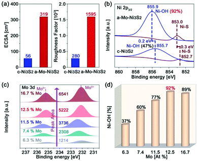
In order to clarify the effect of Mo engineering on hydrogen generation, the electrochemically active surface area (ECSA) and roughness factor (RF) are firstly provided based on their double-layer specific capacitance (Fig. S7 and S8, ESI†). The ECSA and RF of our a-Mo–Ni3S2 catalysts are 319 cm2 and 1595, as shown in Fig. 4a, nearly six times higher than those of c-Ni3S2 (56 cm2 and 280). These data indicate that the apparent active sites of the a-Mo–Ni3S2 electrocatalysts have been significantly increased. To investigate the underlying factors in detail, the high-resolution XPS spectra are employed to study the electronic structural change of the a-Mo–Ni3S2 catalysts after HER with the c-Ni3S2 sample as a control. As shown in Fig. 4b, the binding energies of Ni–OH and Ni–S bonds are more positive with large bias of 0.2 and 0.3 eV, respectively, compared to the c-Ni3S2 electrocatalysts in the Ni 2p3/2 region. The Ni–OH content is also greatly improved to 92% after HER by integrating the respective peak areas, two times higher than the case of c-Ni3S2. The phenomena imply the electron-deficient characteristics of the a-Mo–Ni3S2 catalysts, which have been recognized to help the improvement of Ni sites adsorption ability to targeted active intermediates (OH−) during hydrogen generation.33,34 It is noted that the Mo atoms contribute negligible catalytic activity because of the unchanged Mo6+ oxidation state (Fig. S9, ESI†) that is inactive for HER.35 To elucidate the role of Mo, Ni3S2 products with different Mo contents after HER are investigated by high-resolution XPS spectra (Fig. 4c). The Mo content in all samples is estimated by ICP-MS, which is in good agreement with the calculated results of the respective peak area. It can be observed that all samples show a Mo6+ oxidation state. Impressively, the characteristic peaks of Ni–OH bonds in the Ni 2p3/2 region (Fig. S10, ESI†) have been gradually enhanced with increasing Mo content until 12.5 at%, as shown in Fig. 4d. This result indicates that Mo atoms can promote the formation of Ni–OH bonds. The maximized Ni–OH content is reported to accelerate HER kinetics.14 Direct evidence is provided by their HER polarization curves (Fig. S11, ESI†), where the sample with 12.5 at% Mo exhibits the best HER activity.
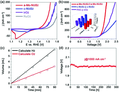
As aforementioned, Mo engineered Ni3S2 catalysts greatly enhanced the HER activity without sacrificing their excellent OER performance. As shown in Fig. 5a, a small overpotential of only 276 mV is required to attain 100 mA cm−2, much lower than those of c-Ni3S2 (318 mV) and the commercial IrO2 and RuO2 catalysts. The corresponding Tafel slope (Fig. S12, ESI†) is 61 mV dec−1, closer to that of RuO2 than c-Ni3S2. The enhanced OER kinetics can also be verified by its higher exchange current density (j0) of 1.39 × 10⁻⁴ mA cm−2 than c-Ni3S2 (2.20 × 10⁻⁵ mA cm−2). The a-Mo–Ni3S2 electrocatalysts can be stable for over 12 h CP at 100 mA cm−2 (Fig. S13, ESI†) without any change in morphology and crystal phase (Fig. S14, ESI†). The improved OER performance is attributed to the introduction of Mo atoms, which can increase the OER active intermediate OOH* content from 4% of c-Ni3S2 to 10% of a-Mo–Ni3S2 according to the XPS results after OER (Fig. S15, ESI†).36 We then assembled a two-electrode alkaline electrolyzer using a-Mo–Ni3S2 as both anode and cathode, delivering current densities of 50 and 100 mA cm−2 at small voltages of 1.61 and 1.67 V, respectively, as shown in Fig. 5b. Even for achieving an ultrahigh current density of 1000 mA cm−2, only a voltage of 1.97 V is required with strong bubble evolution. To highlight the outstanding bifunctional electrocatalytic activity for water splitting, we also assembled c-Ni3S2//c-Ni3S2 and Pt/C//IrO2 as controls. They required higher voltages to obtain the same current density. In addition, the a-Mo–Ni3S2 catalyst displays nearly 100% Faradaic efficiency calculated by comparing the generated H2 and O2 volumes with theoretical values (Fig. 5c). It also possesses high stability for water splitting (Fig. 5d) with a very slight voltage decrease for 300 h CP measurement at 1000 mA cm−2. The water splitting ability of the a-Mo–Ni3S2 electrocatalysts is among the best reported in the literature, showing their fascinating potential for practical application.
Conclusions
In summary, we demonstrated a low-temperature and rapid synthesis of Mo-triggered amorphous Ni3S2 electrocatalysts for the first time by a solid-phase melting strategy. The resulting a-Mo–Ni3S2 catalysts possess exceptionally high activity and stability for both HER and OER in alkaline media, outperforming the commercial noble-metal benchmarks (Pt, IrO2 and RuO2) and other advanced Ni-based electrocatalysts in the literature. Prominently, the a-Mo–Ni3S2 catalysts require ultralow HER overpotentials of 74 and 165 mV to obtain 10 and 100 mA cm−2 with a four times higher TOF of 6.39 s−1 at η = 150 mV in comparison to crystalline Ni3S2. In addition, a small OER overpotential of 276 mV at 100 mA cm−2 is attained. A two-electrode electrolyzer assembled using the a-Mo–Ni3S2 electrocatalysts can achieve a current density of 1000 mA cm−2 at only 1.97 V which is stable for over 300 h. Such fascinating catalytic performances are mainly attributed to the enhanced adsorption ability of Ni active sites to key intermediates of HER as well as the enrichment of OER targeted intermediates caused by Mo engineering. This finding verifies the feasibility in design of highly efficient non-noble electrocatalysts by engineering on surfaces and nanostructures.Conflicts of interest
There are no conflicts to declare.Acknowledgements
This work was supported by the National Natural Science Foundation of China (51672082, 91534122 and 91534202), the Social Development Program of Shanghai (17DZ1200900), the Shanghai Scientific and Technological Innovation Project (18JC1410600), the Program for Shanghai Youth Top-notch Talent, and the Fundamental Research Funds for the Central Universities (222201718002).References
- Z. W. Seh, J. Kibsgaard, C. F. Dickens, I. B. Chorkendorff, J. K. Norskov and T. F. Jaramillo, Science, 2017, 355, 146 CrossRef PubMed.
- I. Roger, M. A. Shipman and M. D. Symes, Nat. Rev. Chem., 2017, 1, 0003 CrossRef.
- X. X. Zou and Y. Zhang, Chem. Soc. Rev., 2015, 44, 5148 RSC.
- Y. Jiao, Y. Zheng, M. Jaroniec and S. Z. Qiao, Chem. Soc. Rev., 2015, 44, 2060 RSC.
- H. J. Yin, S. L. Zhao, K. Zhao, A. Muqsit, H. J. Tang, L. Chang, H. J. Zhao, Y. Gao and Z. Y. Tang, Nat. Commun., 2015, 6, 8 Search PubMed.
- H. S. Oh, H. N. Nong, T. Reier, A. Bergmann, M. Gliech, J. F. de Araujo, E. Willinger, R. Schlogl, D. Teschner and P. Strasser, J. Am. Chem. Soc., 2016, 138, 12552 CrossRef PubMed.
- J. Duan, S. Chen and C. Zhao, Nat. Commun., 2017, 8, 15341 CrossRef PubMed.
- Y. Liu, Q. Li, R. Si, G. D. Li, W. Li, D. P. Liu, D. Wang, L. Sun, Y. Zhang and X. Zou, Adv. Mater., 2017, 29, 1606200 CrossRef PubMed.
- C. L. Hu, L. Zhang, Z. J. Zhao, A. Li and J. L. Gong, Adv. Mater., 2018, 1705538 CrossRef PubMed.
- K. Xu, H. Ding, H. Lv, S. Tao, P. Chen, X. Wu, W. Chu, C. Wu and Y. Xie, ACS Catal., 2016, 7, 310 CrossRef.
- Y. Wu, G. D. Li, Y. Liu, L. Yang, X. Lian, T. Asefa and X. Zou, Adv. Funct. Mater., 2016, 26, 4839 CrossRef.
- L. L. Feng, G. Yu, Y. Wu, G. D. Li, H. Li, Y. Sun, T. Asefa, W. Chen and X. Zou, J. Am. Chem. Soc., 2015, 137, 14023 CrossRef PubMed.
- T. Zhu, L. Zhu, J. Wang and G. W. Ho, J. Mater. Chem. A, 2016, 4, 13916 Search PubMed.
- R. Subbaraman, D. Tripkovic, K. C. Chang, D. Strmcnik, A. P. Paulikas, P. Hirunsit, M. Chan, J. Greeley, V. Stamenkovic and N. M. Markovic, Nat. Mater., 2012, 11, 550 CrossRef PubMed.
- J. Zhang, T. Wang, P. Liu, S. Liu, R. Dong, X. Zhuang, M. Chen and X. Feng, Energy Environ. Sci., 2016, 9, 2789 Search PubMed.
- H. Lin, N. Liu, Z. Shi, Y. Guo, Y. Tang and Q. Gao, Adv. Funct. Mater., 2016, 26, 5590 CrossRef.
- C. Tang, R. Zhang, W. Lu, L. He, X. Jiang, A. M. Asiri and X. Sun, Adv. Mater., 2017, 29, 1602441 CrossRef PubMed.
- X. Zhang, X. Zhang, H. Xu, Z. Wu, H. Wang and Y. Liang, Adv. Funct. Mater., 2017, 27, 1606635 CrossRef.
- S. Magdassi, M. Grouchko, O. Berezin and A. Kamyshny, ACS Nano, 2010, 4, 1943 CrossRef PubMed.
- H. Jiang, H. Zhang, Y. Fu, S. Guo, Y. Hu, L. Zhang, Y. Liu, H. Liu and C. Li, ACS Nano, 2015, 10, 1648 CrossRef PubMed.
- R. D. L. Smith, M. S. Prévot, R. D. Fagan, Z. Zhang, P. A. Sedach, M. K. J. Siu, S. Trudel and C. P. Berlinguette, Science, 2013, 340, 60 CrossRef PubMed.
- C. G. Morales-Guio and X. L. Hu, Acc. Chem. Res., 2014, 47, 2671 CrossRef PubMed.
- A. P. Grosvenor, M. C. Biesinger, R. S. C. Smart and N. S. McIntyre, Surf. Sci., 2006, 600, 1771 CrossRef.
- M. C. Biesinger, B. P. Payne, A. P. Grosvenor, L. W. M. Lau, A. R. Gerson and R. S. C. Smart, Appl. Surf. Sci., 2011, 257, 2717 CrossRef.
- H. Zhang, H. Jiang, Y. Hu, H. Jiang and C. Li, Green Energy Environ., 2017, 2, 112 CrossRef.
- T. I. Korányi, I. Manninger, Z. Paál, O. Marks and J. R. Günter, J. Catal., 1989, 116, 422 CrossRef.
- H. Liu, Q. He, H. Jiang, Y. Lin, Y. Zhang, M. Habib, S. Chen and L. Song, ACS Nano, 2017, 11, 11574 CrossRef PubMed.
- J. G. Choi and L. T. Thompson, Appl. Surf. Sci., 1996, 93, 143 CrossRef.
- T. Tian, L. Huang, L. Ai and J. Jiang, J. Mater. Chem. A, 2017, 5, 20985 Search PubMed.
- H. Wang, X. Cheng, B. Xiao, C. Wang, L. Zhao and Y. Zhu, Catal. Surv. Asia, 2015, 19, 78 CrossRef.
- B. Liu, Y. F. Zhao, H. Q. Peng, Z. Y. Zhang, C. K. Sit, M. F. Yuen, T. R. Zhang, C. S. Lee and W. J. Zhang, Adv. Mater., 2017, 29, 1606521 CrossRef PubMed.
- D. Merki, S. Fierro, H. Vrubel and X. Hu, Chem. Sci., 2011, 2, 1262 RSC.
- Z. Zhou, X. Gao, J. Yan and D. Song, Carbon, 2006, 44, 939 CrossRef.
- G. X. Chen, C. F. Xu, X. Q. Huang, J. Y. Ye, L. Gu, G. Li, Z. C. Tang, B. H. Wu, H. Y. Yang, Z. P. Zhao, Z. Y. Zhou, G. Fu and N. F. Zheng, Nat. Mater., 2016, 15, 564 CrossRef PubMed.
- J. D. Benck, Z. Chen, L. Y. Kuritzky, A. J. Forman and T. F. Jaramillo, ACS Catal., 2012, 2, 1916 CrossRef.
- J. C. Dupin, D. Gonbeau, P. Vinatier and A. Levasseur, Phys. Chem. Chem. Phys., 2000, 2, 1319 RSC.
Footnote |
| † Electronic supplementary information (ESI) available. See DOI: 10.1039/c8qm00178b |
| This journal is © the Partner Organisations 2018 |

