Design and preparation of quasi-spherical salt particles as water-soluble porogens to fabricate hydrophobic porous scaffolds for tissue engineering and tissue regeneration†
Xiangyu
Liang
,
Yongli
Qi
,
Zhen
Pan
,
Yao
He
,
Xiangnan
Liu
,
Shuquan
Cui
and
Jiandong
Ding
 *
*
State Key Laboratory of Molecular Engineering of Polymers, Department of Macromolecular Science, Fudan University, Shanghai 200438, China. E-mail: jdding1@fudan.edu.cn; Tel: +86-21-31243506
First published on 12th June 2018
Abstract
The design and preparation of appropriate porogens are critical in the fabrication of porous scaffolds for tissue engineering and tissue regeneration. Our analysis based on percolation theory reveals that a spherical porogen is better than a cubic porogen. Nevertheless, while porous scaffolds with spherical interior pores have exhibited advantages over those of cubic pores, salt as the most popular and convenient porogen can only be shaped cubically due to the principle of crystallography. Hererin, we propose a strategy to prepare, indirectly, quasi-spherical salt macroparticles simply via gluing small salt particles by sugar melt. The popular biodegradable polymer poly(D,L-lactide-co-glycolide) (PLGA) was employed as the hydrophobic matrix, and polymeric scaffolds with quasi-spherical pores were successfully fabricated by room-temperature compression molding and particulate leaching. Compared to PLGA scaffolds fabricated by conventional cubic salt macroparticles, our improved scaffolds exhibited excellent pore interconnectivity and fewer porogen residues. Two additional advantages of the new fabrication approach were also found: one is quicker porogen leaching by water in the fabrication of PLGA scaffolds, which might be owing to easier water penetration into the intervals of these microparticles; the other is favourable cell adhesion and osteogenic differentiation on the pore wall, which might be attributed to the rough interior surfaces templated from the porogen surfaces composed of many microparticles. The new approach and resultant scaffolds are promising in regenerative medicine.
1. Introduction
Porous scaffolds play a very important role in tissue engineering and regenerative medicine,1–3 and therefore the fabrication techniques for porous scaffolds are pivotal in the corresponding biomaterial fields.4–10 Among many strategies to fabricate three-dimensional porous scaffolds, porogen leaching has widely been applied owing to its much convenience, extra structure support for scaffolds and easier control for pores by regulating the porogens.11–17 It is thus critical to design and prepare appropriate porogens.Salt particles are the most popular kind of porogens, owing to not only their low cost, but also the convenience and biocompatibility of using water as a leaching medium.18–24 Yet salt can only be prepared in a cubic or quasi-cubic shape according to the principle of crystallography. In 2001, Peter Ma's group suggested an excellent strategy to prepare a spherical paraffin porogen and achieved “biodegradable polymer scaffolds with a well-defined interconnected spherical pore network”.14 Being inspired by their idea, our group made comparative studies of poly(D,L-lactide-co-glycolide) (PLGA) porous scaffolds prepared by both cubic salt porogens and spheric paraffin porogens, and found that the application of spherical porogens can not only improve the interconnectivity of the resultant porous scaffolds, but also enhance the mechanical properties of the scaffold of high porosity.25 Some other pertinent efforts of spherical porogens to fabricate tissue engineeiring scaffolds have also been reported.26–28 Nevertheless, 17 years later, salt porogens still have taken up absolute superiority in fabricating porous scaffolds in the formulism of porogen leaching for tissue engineering and tissue regeneration. The main reason comes from the fact that spherical porogens are mainly made of organic matter, leading to two significant drawbacks: the leaching process should use an organic solvent; the residual porogen leads to biocompatibility problems. So, it is much desired to prepare water-soluble porogens appropriate for fabrication of tissue engineering scaffolds efficiently. However, it is challenging to prepare water-soluble and biocompatible porogens of spherical external shape, and a new idea for a novel strategy is called for.
Hererin we put forward a new yet facile strategy to prepare quasi-spherical water-soluble porogens. In this paper, we make an analysis of porous scaffolds templated by a porogen network in light of percolation theory in the Introduction section; then we describe the new preparation approach of the quasi-spherical salt porogens and the resultant porous scaffolds in the main body of the manuscript.
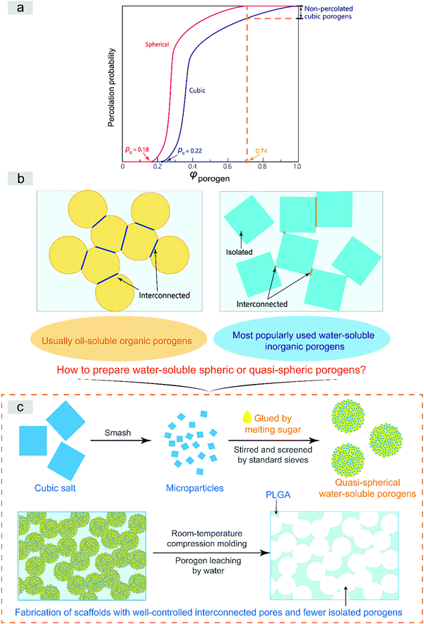
The interconnected network can be well described by percolation theory for a geometrical phase transition.29–31 The interconnected porous structure of a scaffold is just templated from the percolated porogen network in the formulism of the porogen-leaching approach. The pecolation can only be achieved at high porogen volume fractions, as schematically presented in Fig. S1 (ESI†). Assuming a random spatial distribution of a porogen of unique sizes, the critical volume fraction of percolation φc occurs at 0.18 in the case of spheres.32 The critical value for cubic particles is a bit complicated. Based on the pertinent literature,31–33 we summarize that the value is around 0.22, anyway higher than 0.18. On the other hand, the close-compact volume fraction of spheres reads 0.74.34 Due to compression in molding to fabricate tissue engineering scaffolds, the actual value might be higher than 0.74, but anyway lower than 1, which is theoretically the case of cubic particles. In summary, spherical porogens exhibit a lower critical percolation volume fraction and lower close-compact volume fraction than cubic porogens, as summarized schematically in Fig. 1a.
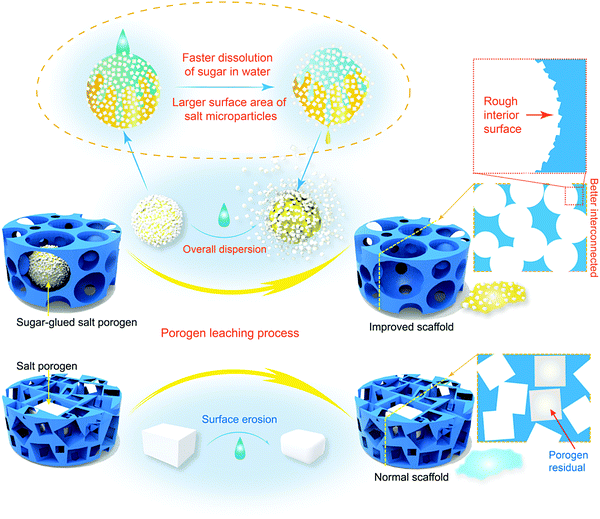
Furthermore, Fig. 1b illustrates that the interconnections between two spherical porogens in contact is relatively unique while those between two cubic ones are diverse. So, our theoretical analysis illustrates clearly that spherical porogens are better than cubic porogens if the interconnectivity of a tissue engineering scaffold is well concerned. However, as also briefly summarized in Fig. 1b, there is a dilemma between using cubic and spherical porogens in the fabrication of tissue engineering scaffolds in the formulism of porogen leaching, because those spherical porogens are not water-soluble and those water-soluble porogens are cubic. Herein we suggest a strategy of using a sugar-glued salt porogen, which dexterously sidesteps this puzzle. An indirect way to prepare the sugar-glued salt porogen is schematically presented in Fig. 1c, and more details will be shown in the Materials and methods section.
We employed PLGA as the scaffold matrix and mesenchymal stem cells (MSCs) as a model cell type. PLGA is a very popular biodegradable polymer,11,14,35,36 and MSCs are an important type of seed cells in tissue engineering and tissue regeneration.37–40 Thus our work might be of general interest and impact. Besides excellent interconnectivity, the porogen leaching process and the resultant porous scaffold exhibited some unexpected yet reasonable behaviors, which will also be reported in the present paper.
2. Materials and methods
2.1. Porogen preparation
The preparation procedure is schematically presented in Fig. S2 (ESI†). For cubic porogens, granular sodium chloride (Shanghai Qiangshun Chemical Co., Ltd) was poured into standard sieves (Type 8411) fixed in a sieve shaker. Then we carried out wobbling for half an hour. Cubic macroparticles in the range of 300–450 μm were collected and preserved in a dessicator as standby porogens.Quasi-spherical macroporogens were prepared based on the microparticles. Granular sodium chloride was smashed with a high-speed disintegrator (Shanghai Dianjiu Machinery Manufacturing Co., Ltd) into microparticles of 1–15 μm. Those salt microparticles were then mixed with sucrose (Shanghai Qiangshun Chemical Co., Ltd) in a flask. The mass ratio of sucrose and salt microparticles was 1![[thin space (1/6-em)]](https://www.rsc.org/images/entities/char_2009.gif) :
:![[thin space (1/6-em)]](https://www.rsc.org/images/entities/char_2009.gif) 5. The mixture was heated to approximately 170 °C and mechanically stirred at 250 rpm for half an hour. The resulting mixture was immediately poured into standard sieves which were firmly fixed in a sieve shaker under the exposure of an infrared lamp, then wobbling was performed for half an hour. We collected quasi-spherical sugar-glued salt porogens with particle sizes in the range of 300–450 μm. The porogens were preserved in the dessicator.
5. The mixture was heated to approximately 170 °C and mechanically stirred at 250 rpm for half an hour. The resulting mixture was immediately poured into standard sieves which were firmly fixed in a sieve shaker under the exposure of an infrared lamp, then wobbling was performed for half an hour. We collected quasi-spherical sugar-glued salt porogens with particle sizes in the range of 300–450 μm. The porogens were preserved in the dessicator.
2.2. Fabrication of PLGA scaffolds using the pre-prepared porogens
The procedure of scaffold fabrication is schematically presented in Fig. S3 (ESI†). Three-dimensional porous scaffolds were fabricated by the technique of compression molding and particulate leaching at room temperature.41 PLGA particles with a lactide/glycolide molar ratio (LA/GA) of 85/15 (2.93 dL g−1, Purac Inc., Netherlands) were dissolved overnight in dichloromethane at 4 °C with the concentration of 7.5 g mL−1, and mixed with sugar-glued salt porogens with their amounts dependent upon the desired scaffold porosities. The mixtures were stirred until appropriate viscosity and homogeneous dispersion of the porogen. Then we performed a quick mould filling, followed by 24 hours of mould pressing. These actions and the later mould releasing were all carried out at room temperature.After mould releasing, the shaped mixture of PLGA and porogens was immersed into a beaker with 500 mL deionized water to leach out the porogens. The deionized water was changed every hour until no precipitation was observed upon addition of silver nitrate, and the time was defined as the necessary leaching time by us. PLGA scaffolds were placed into the vacuum drying oven (≥755 mmHg) for 48 h, and then porous PLGA scaffolds were obtained for subsequent testing.
2.3. AFM test of the interior surface roughness of the resultant PLGA scaffolds
An Atomic Force Microscope (AFM, Bruker Multimode 8, USA) was employed to measure the interior surface roughness for both normal and improved scaffolds. Prior to the AFM testing, the scaffold slices were gently stuck on the specimen holder. Thereafter, the Peak Force Tapping mode with tip type of OMCL-AC160TS-R3 (resonant frequency: 300 kHz; spring constant: 26 N m−1; China) was used in the AFM test. Nanoscope Analysis, a Bruker's offline data processing software, was used to analyze the surface roughness of the scaffold slices.2.4. TGA analysis of sugar-glued salt porogens to detect the content of salt microparticles in the composite macroparticles
Thermogravimetric Analysis (TGA, PE, USA) was carried out to detect the fraction of salt microparticles fsalt in the sugar-glued salt porogen under a nitrogen atmosphere with a flow rate of 40 mL min−1. We examined the weight from 50 °C to 800 °C at a heating rate of 10 °C min−1. According to the known densities of salt and sugar (ρsalt = 2.17 g cm−3, ρsugar = 1.58 g cm−3)42,43 and the determined weight fractions of salt and sugar from TGA analysis, we calculated ρporogen, the density of spherical sugar-glued salt porogen using the following equation| ρporogen = fsaltρsalt + (1 − fsalt)ρsugar | (1) |
2.5. GPC detection to measure the molecular weight of PLGA before and after porogen leaching
Gel permeation chromatography (GPC, Agilent/Wyatt 1100, USA) was used to measure the relative molecular weight of a PLGA polymer in the porous scaffolds that were generated by normal cubic and improved spherical sugar-glued salts as porogens after particle leaching in stirring deionized water. The calibration curve was set by uniform polystyrene standards. The tetrahydrofuran (THF) phase was used in the GPC measurements with a flow rate of 1.0 mL min−1 at the temperature of 35 °C.2.6. SEM-EDS observations of the as-prepared porogens and the as-fabricated porous scaffolds
Scanning electron microscopy (SEM) was carried out to observe the morphology of the porogen particles and the interior surface of the PLGA scaffold slices. And energy dispersive X-ray spectroscopy (EDS, Bruker, Germany) was employed to analyze the residual chlorine in the PLGA scaffold slices. Before the SEM observation, a thin layer of gold was sputtered on the surface of the samples for 60 s. The heater voltage in the microscope (TESCAN VEGA TS 5136MM, Czech) was set at 20 kV.Based on the SEM images, at least 100 pores in the normal or improved scaffolds were observed in the size measurement, and were treated with a Nano Measurer (freely available at http://nano-measurer.software.informer.com/) to analyze the distribution of pore size for each kind of scaffold.
2.7. Micro-CT observation of the as-fabricated porogens and porous scaffolds
We used a high-resolution micro-CT imaging system (Bruker SkyScan 1176, USA) to observe the salt particles, sugar particles, and sugar-glued salt porogens. These particles were stuck on the surface of a foam board for subsequent micro-CT observation.We also observed the morphology of the PLGA/porogen composites before leaching and the residual porogens in the polymeric scaffolds after leaching with micro-CT. Prior to the observation, we enhanced the contrast of the polymer using an inorganic ion. PLGA scaffolds were dipped into 0.1 mol mL−1 iron chloride solution overnight. After condensing with liquid nitrogen, we placed them into the vacuum freeze drying oven for 48 h to obtain ultima scaffolds for subsequent micro-CT testing.
The scanning parameters were set as follows: spatial resolution of 9 μm pixel size; X-ray tube voltage of 50 kV; X-ray tube current of 497 mA; optical filter of Al 0.2 mm; scanning angular scope of 180° and rotation step of 0.40°. The software GPUReconServer along with the micro-CT system was utilized to analyze and reconstruct all planograms under the identical optimized parameters. After reconstructing, CTAn, another software in the micro-CT system, was used to analyze the porogen vestigital and closed porosity in the pre-set region of interest. The realistic 3D visualization of the scaffolds was performed by CTvox, which is also software within the micro-CT system.
We employed analysis of cross section measuring44 to calculate the fraction of residual particles in the scaffolds after porogen leaching. According to the concept that a three-dimensional scaffold can be divided into layers, representative cross sections were used to reflect the three dimensional structure by integral. The lossless pore structure of the sample cross section is a precondition for this method, thus high-resolution micro-CT images were combined to obtain the cross sections of the scaffolds.
Based on the cross section images, we used ImageJ (freely available at http://imagej.nih.gov/ij/) to calculate the area of residual porogens (Sr) and total area of the cross section (St). Under a given porosity of the scaffold φv, the fraction of residual porogens θ can be readily determined as
 | (2) |
2.8. Measurements of theoretical and experimental porosities of the resultant PLGA scaffolds
Under a given density of bulk polymer (ρPLGA = 1.25 g cm−3) and that of the porogen ρporogen, the theoretical scaffold porosity is easily calculated by | (3) |
 | (4) |
The experimental porosity was determined by a modified liquid replacement method.45 We used anhydrous ethanol (AR 99.7%, Shanghai Titan Scientific Co., Ltd) as the liquid to measure the volume of the pores within the scaffold. A dry porous scaffold with mass mscaffold was put into a glass bottle with alcohol. We sufficiently vacuumized the bottle until the inner pores of the scaffold were completely penetrated by the alcohol. We then immediately put it into a weighing bottle full of alcohol, which was weighed up as m1. After the porous scaffold was removed carefully from the weighing bottle, we recorded the mass of the weighing bottle with residual alcohol as m2. Experimental porosity was then calculated by
 | (5) |
2.9. Compression tests to determine the mechanical properties of the resultant PLGA scaffolds
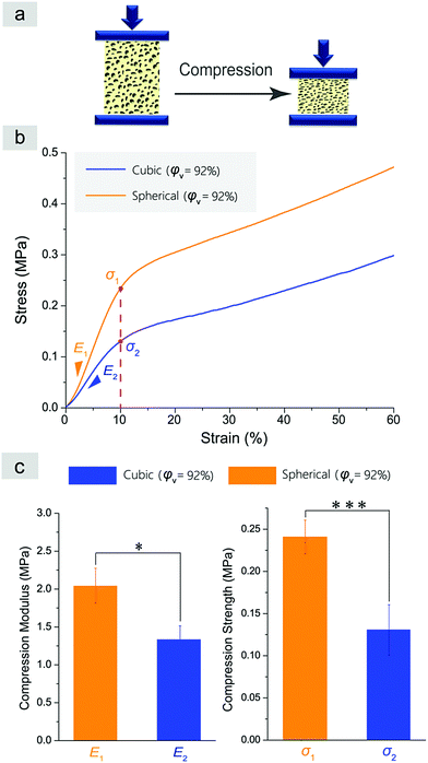
Cylindrical porous scaffolds with a diameter of 10 mm and a height of 10 mm were used as testing samples. Mechanical tests were performed using an electronic universal testing machine (CMT4104, Shenzhen SANS Testing Machine Co., Ltd, China) at a testing speed of 6.0 mm min−1. We exposed a strain displacement until 90% under constant temperature and humidity conditions. Compressive modulus (E) and compressive strength σ are commonly used to characterize the mechanical properties of a porous scaffold. Thereinto, the compressive modulus E was determined as the slope of the initial linear section of the stress–strain curve; the stress at 10% strain (σ10) indicated the compressive strength for a scaffold without a yielding point.2.10. Cell adhesion on the interior surface of the porous scaffolds
MSCs were isolated from the bone marrow of 7-day old neonatal Sprague-Dawley (SD) rats purchased from Shanghai Laboratory Animal Research Center (China) and dealt with following our previous protocol.46–49 In this study, we seeded 20 × 104 cells onto a scaffold slice of 10 mm in diameter and 2 mm in thickness. Before cell seeding, each slice of the scaffolds was sterilized by 70% (v/v) ethanol solution for 30 min, and immersed them into phosphate buffer saline (PBS, Gibco) and then modified minimum essential medium (MEM-α, Sigma) to remove the ethanol three times (5 min for each time).Scaffolds with cells were cultured in a culture medium composed of 90% MEM-α supplemented with 10% fetal bovine serum (FBS, Gibco) in an incubator at 37 °C with 5% CO2 and 95% humidity.50 After 7 days, cells on the interior surface of the scaffolds were gently fixed with 4% paraformaldehyde for 1 h. Then dehydration by gradient ethanol was carried out, gold was sputtered, and cell adhesion was observed by SEM.
2.11. Cell proliferation in basal medium
After 7 days of culture, MSCs on the scaffolds were gently rinsed three times via PBS. The samples were fixed into 4% paraformaldehyde at room temperature for 10 min and rinsed with PBS for 5 min in three runs, then treated with 0.1% Triton X-100 for membrane permeation for 10 min and rinsed with PBS for 5 min in three runs again. In order to observe the filamentous actins (F-actins) of MSCs, the samples were incubated with 1 mg mL−1 phalloidin–tetramethyl rhodamine B isothiocyanate (phalloidin-TRITC, Sigma). The cells were incubated at room temperature in the dark for 1 h, and then rinsed with PBS for 5 min in three runs. Finally, 5 mg mL−1 4′,6-diamidino-2-phenylindole (DAPI, Sigma) was added to label the nuclei at room temperature in the dark for 10 min and thoroughly rinsed with Milli-Q water several times. The immunofluorescence staining of the cells was observed under an inverted fluorescence microscope (Axiovert 200, Zeiss, Germany). The fluorescence micrographs were captured by using a digital CCD camera (AxioCam HRC, Zeiss, Germany). The original micrographs were treated by the software ZEN (AxioCamMR3, Zeiss, Germany), and split into red and blue channels.51The assay of 3-(4,5-dimethylthiazol-2-yl)-2,5-diphenyltetrazolium bromide (MTT) was used to measure the viability of the MSCs after culture for 1 day, 3 days and 7 days on both kinds of scaffolds in the basal medium. The MTT solution (1 mL, 0.5 mg mL−1) was added into a 12-well culture plate (Corning, USA). The samples were then placed in the incubator (Heraeus, Germany) at 37 °C with 5% CO2 and 95% humidity for 4 h. One milliliter of dimethylsulfoxide (DMSO, Gibco) was added into the 12-well culture plate after removing the medium. Ten minutes later, 200 μL solution in the 12-well culture plate was absorbed by pipettes to a 96-well culture plate. The absorbance value of purple crystals at 492 nm was measured by enzyme-linked immunosorbent assay (ELISA, Thermo Multiscan MK3, USA). For a well without cells, 200 μL DMSO was added as the blank control.
2.12. Cell differentiation in osteogenic induction medium
MSCs in the scaffolds were also induced towards osteoblasts in the differentiation medium, which contained 50 mM ascorbic acid-2-phosphate, 10 mM β-glycerophosphate and 100 nM dexamethasone as well as high-glucose Dulbecco's modified Eagle medium (DMEM, Gibco). After inducing for 6 days, the number of cells in each scaffold was detected by fluorometric analysis of DNA content using Hoechst 33258 (Sigma),52 with a solution of highly polymerized calf thymus DNA as a standard. The alkaline phosphatase (ALP) was stained using Sigma kit 85L1.To determine the ALP activity, the reaction product p-nitrophenol (PNP) of the substrate p-nitrophenyl phosphate (PNPP, Sigma) catalyzed by ALP was dissolved in THF, and then measured by ELISA at 570 nm. The ALP activity per cell was calculated through the total ALP activity in each slice of the scaffolds and the associated cell number per slice, with the protocol described in our previous paper.52
2.13. Statistical analysis
The quantitative results are shown as mean ± standard deviation. Data were analyzed by unpaired Student's t-tests to examine the difference between the two relevant samples. Statistically significant differences are denoted as “*” for p < 0.05, “**” for p < 0.01, and “***” for p < 0.001 between the two examined groups.3. Results
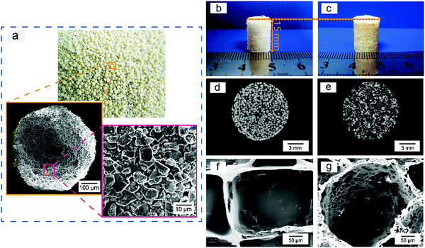
Sugar-glued quasi-spherical salt macroparticles were prepared by the procedure schematically shown in Fig. S2 (ESI†). Granular cubic salt was smashed with a high-speed disintegrator, resulting in salt microparticles with sizes of 1–15 μm. Then, the salt microparticles were glued by sugar melt and shaken to achieve quasi-spherical sugar-glued salt macroparticles. The prepared quasi-spherical porogens with uniform dispersion and slight yellow color are shown in Fig. 2a.We also carried out micro-CT of pure salt, pure sugar and the sugar-glued salt porogen, with some demonstrated images shown in Fig. S3 (ESI†). Salt exhibited much stronger X-ray absorption than sugar (Fig. S3a and b, ESI†). The composite macroparticles are composed mainly of salt microparticles stuck on the surface of melting sugar particles, as illustrated in the cross sectional image (Fig. S3d, ESI†) and the realistic 3D visualization (Fig. S3e, ESI†). So, the minor component of sucrose melt formed a continuous and thin layer connecting the dispersed salt crystals. The porogen was tough and available for further polymer processing by compression molding.
We used compression molding and particulate leaching at room temperature to fabricate PLGA porous scaffolds, with the procedure schematically presented in Fig. S4 (ESI†) and the polymer–porogen ratio listed in Table S1 (ESI†). Improved porous scaffolds were templated with the sugar-glued spherical salt particles. The porogen of pre-defined sizes of 300–450 μm was filtrated and collected by strong wobbling of pre-sized sieves. The normal scaffolds using similar-size cubic salt macroparticles were also fabricated as the control group. The as-fabricated normal and improved cylindrical porous scaffolds had a diameter of 10 mm and height of 15 mm.
The polymer–porogen composites after compression molding yet before leaching of the porogens are shown in Fig. 2b and c for cubic salt and sugar-glued quasi-spherical salt as porogens, respectively. The scaffold prepared by the improved porogen particles was slightly yellow due to the presence of sugar upon heating. Micro-CT cross sections of the normal and improved PLGA/porogen composites are shown in Fig. 2d and e, which demonstrated the distribution of the particles in the polymer matrix.
We also carried out SEM experiments to observe the interior pore structures of both scaffolds after porogen leaching, with high magnification results shown in Fig. 2f and g. Some low magnification SEM images are shown in Fig. S5a and b (ESI†), which demonstrated that the improved scaffolds had spherical macropores with many interconnected pores. The pore-size distribution of the PLGA porous scaffolds is displayed in Fig. S5c and d (ESI†), which illustrated that the improved scaffold had more homogeneous macropores than the normal scaffolds.
AFM was employed to quantify the roughness of the interior surface of the scaffolds, with the 3D images shown in Fig. 3. It is not easy to visualize the interior surface of a 3D scaffold slide, and the probability of success in such an AFM test is very low. The arithmetic average roughness (Ra) and the root-mean-square roughness (Rq) of the normal scaffold read 9.5 nm and 13.8 nm, respectively. For the improved scaffold, they were 239 nm and 317 nm, respectively. So, our improved scaffolds exhibited much rougher pore surfaces.
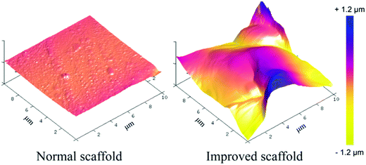 | ||
| Fig. 3 Characterization of the interior surface roughness of the normal and improved scaffolds by AFM analysis. The color scale bar represents the height scale along the Z axis. | ||
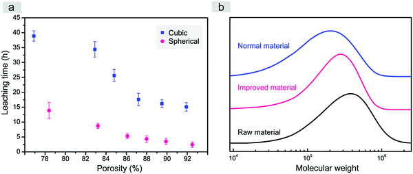
In this study, just water was used as the leaching solvent in both cases of fabrication of the scaffolds templated by spherical and cubic porogens. High and adjustable porosities were obtained. It is very interesting that the better interconnectivity of the improved scaffold was confirmed not only by the interconnected pores, but also by the much quicker leaching when our spherical sugar-glued salt macroparticles were employed as the porogen, as indicated in Fig. 4a.
Less time for porogen leaching improves the efficiency of scaffold fabrication, which is not trivial in biomaterial engineering. It is well known that the solubility of sucrose in water is much higher than that of NaCl (for instance, 200 g versus 36 g in 100 mL water at 20 °C).53 The shorter necessary leaching time might be related to easier water dissolution of the sucrose thin layer, which then generates large erosion surfaces of the salt crystals.
More importantly, according to the molecular weight test of PLGA polymers in the normal and improved scaffolds with the same mass ratio between polymer and porogen in Fig. 4b, the shorter necessary leaching time could significantly decrease the extent of polymer degradation in the process of leaching by water. It has been proved that the degradation of porous scaffolds has a close connection with their mechanical properties and cell behaviours.41,54,55 Shorter necessary leaching time is a highlighted advantage beyond our initial expectation when we designed such a water-soluble spherical porogen to fabricate improved porous scaffolds of biodegradable PLGA.
We also determined the salt content in the quasi-spherical porogen and examined the relation between the porogen weight fraction and the resultant volume fraction of the pores, namely, the porosity of the scaffolds, with the results shown in Fig. 5. Considering that the composite quasi-spherical porogen is composed of salt and sugar with different heat stabilities, we employed TGA to characterize the content of salt microparticles in the quasi-spherical sugar-glued salt porogens. The corresponding TGA curves are presented in Fig. 5a. The fraction of salt microparticles in the sugar-glued salt porogen was determined to be about 65%. According to the known densities of salt and sugar and the determined weight proportion of salt over sugar, we determined the density of the spherical sugar-glued salt porogen as 1.96 g cm−3 by eqn (1).
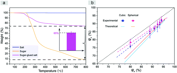 | ||
| Fig. 5 (a) TGA curves of salt, sugar and sugar-glued salt. Inset indicates that the weight fraction of salt microparticles in the sugar-glued salt porogens is about 65% (n = 3). The maximum temperature was higher than the melting point of sugar yet lower than that of salt. (b) Porosity of the porous PLGA scaffolds after leaching the normal cubic salt or novel spherical sugar-glued salt (pore size: 300–450 μm), φv, as a function of φw, the weight content of particulates over the total weight of the porogen and PLGA composite before leaching by water. The dashed lines are obtained by linear regression of the experimental data, and the solid lines present the theoretical relations between φv and φw in eqn (3). Both theoretical lines and experimental data are below the dotted line, because the densities of the porogens are higher than that of the PLGA polymer. | ||
The theoretical and experimental porosities of the two kinds of porous scaffolds are summarized in Fig. 5b. Experimental porosities measured by the liquid replacement method were slightly higher than the corresponding theoretical ones due to the contribution of micropores generated during evaporation of the organic solvent of PLGA in the process of scaffold fabrication. Compared to the cubic salt porogen, the sugar-glued quasi-spherical salt porogen had a lower density due to the presence of sugar. So the quasi-spherical porogens occupied a larger volume under the same mass, which led to a higher porosity of the improved scaffold under a given weight fraction of porogen over the total weight of porogen and polymer.
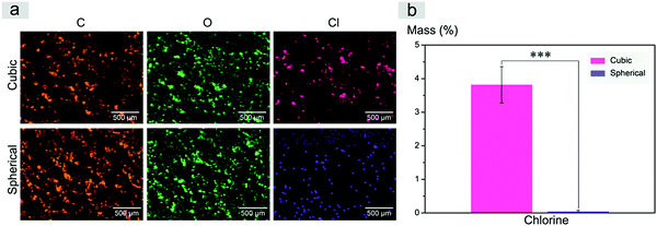
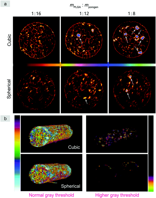
Inspired by a previous work,56 we used SEM-EDS to quantitatively characterize the residual salt porogens of the PLGA scaffolds by measurement of the chlorides. The results for the scaffolds with a polymer–porogen weight ratio of 1![[thin space (1/6-em)]](https://www.rsc.org/images/entities/char_2009.gif) :
:![[thin space (1/6-em)]](https://www.rsc.org/images/entities/char_2009.gif) 16 are shown in Fig. 6. The color in the image is artificial, and the different colors for Cl are just for highlighting the difference of this element between the two samples. Both the observation of EDS mapping in Fig. 6a and the statistical histogram in Fig. 6b illustrate much less chlorine residual in the improved scaffolds.
16 are shown in Fig. 6. The color in the image is artificial, and the different colors for Cl are just for highlighting the difference of this element between the two samples. Both the observation of EDS mapping in Fig. 6a and the statistical histogram in Fig. 6b illustrate much less chlorine residual in the improved scaffolds.
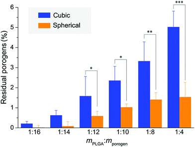
Micro-CT is a powerful tool to observe cross sections of three-dimensional objects in a noninvasive way. Here we employed micro-CT to observe not only the pores of the PLGA scaffolds, but also the residual porogens, with some typical images shown in Fig. 7 and Fig. S6 (ESI†). Since the X-ray absorption of the PLGA scaffolds was weak but very strong for the salt particles, a treatment by an iron chloride solution was introduced by us to enhance the imaging of the PLGA matrix. With the decrease of porosity, there is an increasingly evident porogen residue in the normal scaffolds relative to the improved scaffolds.
The micro-CT images were herein used to quantify the fraction of residual porogens in the scaffolds after 12 hours of particle leaching with changing water every 2 h. As shown in Fig. 8, the normal scaffolds exhibited significantly more porogen residues than the improved scaffolds especially in the cases of less porogens and less high porosities, which further verified the previous results observed in Fig. 7a and Fig. S6 (ESI†).
We also characterized the mechanical properties of the resultant scaffolds. A compression test was carried out as schematically presented in Fig. 9a. It is well known that compressive modulus (E) and compressive strength (σ) characterize the mechanical properties of a porous scaffold.57Fig. 9b and c demonstrate the results of the compression tests of the normal and improved cylindrical porous PLGA scaffolds with a similar porosity of about 92%. No yielding was observed in Fig. 9b. The slope in the elastic deformation region represents the compressive modulus E, and the stress at 10% strain indicates the compressive strength for a material sample without yielding point. The improved scaffolds with spherical macropores showed higher compressive modulus and strength than the normal scaffolds with cubic macropores (Fig. 9c).
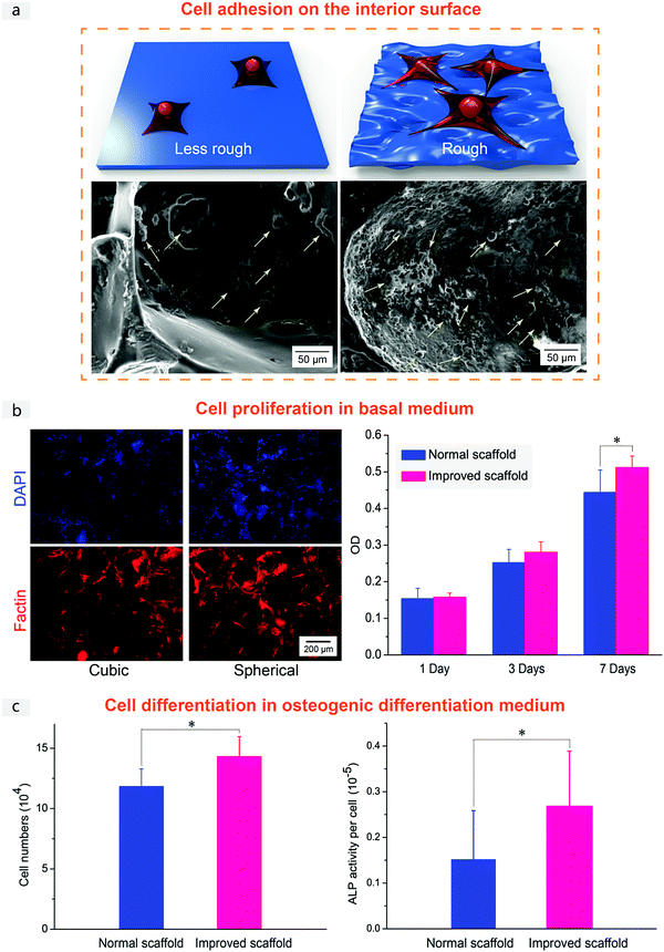
Finally, we checked the cell compatibility of the PLGA porous scaffolds. Fig. 10 demonstrates the adhesion of MSCs on the interior surface, cell proliferation in a basal medium and cell differentiation in an osteogenic differentiation medium for the normal and improved scaffolds. Besides preferable pore interconnectivity, we anticipated that the superior cell responses in the improved scaffold might be attributed also to the pore-wall microstructure. The interior surface of the improved scaffold was observed to be rough (Fig. 3 and 10a), which is reminiscent of the salt microparticles as the main component of the sugar-glued spherical salt macroparticles as the porogen (Fig. 2). The good interconnectivity of the scaffold enhanced the substance exchange, and the surface roughness has been reported to be beneficial for cell growth.58–60 Better cell adhesion was also seen from our cell observations, as shown in Fig. 10a and Fig. S7 (ESI†).
Fluorescence micrographs in Fig. 10b displayed MSCs cultured in the basal medium on PLGA scaffolds with cubic salt and spherical sugar-glued salt as porogens. The right data in Fig. 10b also showed MTT measurements of viability of MSCs in the basal medium. Both scaffolds exhibited good cell viability and proliferation. A significant difference was found after 7 days of culture, illustrating better cell proliferation in the improved PLGA scaffolds.
The better proliferation was reproduced in the osteogenic induction medium, as shown in Fig. 10c. And the improved scaffolds were beneficial for osteogenic differentiation. Pore-wall microstructure topography templated by the improved porogens led to better cell adhesion, proliferation and differentiation, consistent with the previous reports about the effects of material microstructures on cell behaviors.61–65
4. Discussion
Porogen leaching is a popular approach to fabricate tissue engineering porous scaffolds via negative templating.66–71 An appropriate porogen plays a critical role in the scaffolding. The present paper reports a technique of preparation of water-soluble and quasi-spherical salt porogen and fabrication of the corresponding PLGA porous scaffolds.4.1. Comparative analysis of the necessity to prepare spherical salt porogens
We first address and answer two basic questions: why spherical, and why salt.Moreover, spherical particles provide a homogeneous pore structure throughout the scaffold (Fig. 2 and Fig. S5, ESI†). The homogeneity of the pore structure plays a significant role in the mechanical property of the resultant three-dimensional scaffold.
Sugar is of good water solubility, and sucrose or fructose spheres have been tried to prepare tissue engineering scaffolds. But they are very supple and prefer to stick to each other, and thus are difficult to handle during, for instance, pre-mixing with polymers for compression molding. The extremely hygroscopic property of sugar makes the prepared spheres hard to disperse evenly and hard to be stored. So, salt porogens are better than sugar porogens. But the problem comes from the difficulty to obtain spherical macroparticles of common salts such as NaCl.
It is impossible to obtain perfectly spherical salt macroparticles due to the crystallization principle. In contrast, only interfaces with low Miller indexes are left, and thus macrocrystals are usually cubic or quasi-cubic. In spite of this, a pioneering work to prepare quasi-spherical salt particles was carried out in 2004, when Gross and Rodríguez-Lorenzo tried a high-temperature flame technique to burn the edges of cubic salt.74 Such a technique is, albeit elegant, of low efficiency. Facile material techniques are always important in the applied material fields.
It can be seen that all of the three previous techniques have not been applied widely in the fields of tissue engineering although they have been released more than 10 years ago. It is much desired to prepare spherical or quasi-spherical water-soluble porogens mainly composed of salt efficiently. The present paper reports, for the first time, such a technique via an indirect approach to prepare sugar-glued salt particles. We designed and prepared quasi-spherical salt macroparticles via sugar-gluing plenty of cubic salt microparticles, as schematically illustrated in Fig. 1c and Fig. S2 (ESI†).
4.2. Advantages of the scaffolding technique using our quasi-spherical sugar-glued salt porogen
The composite porogen of sugar-glued salt particles in this paper is convenient in handling during fabrication of tissue engineering scaffolds. The corresponding scaffolding process and the resultant porous scaffolds exhibited significant advantages as follows:The vertical coordinate “percolation probability” in Fig. 1a is defined as the probability of any particle or porogen belonging to any percolation network. It is thus equal to the fraction of percolated particles among all of the particles. Under ideal conditions of a templating approach to prepare an interconnected scaffold, the percolation probability determines the porosity of the resultant scaffold, namely, the volume fraction of interconnected pores over the whole porous scaffold. Fig. 1a indicates that the percolation probability of porogens and thus the porosity of the resultant scaffold is higher in the case of spherical porogens than in the case of cubic porogens.
Moreover, as shown in Fig. 1b, it is not difficult to find that the interconnections between two spherical porogens in contact is relatively unique and homogeneous while those between two cubic ones are diverse and heterogeneous, which further illustrates clearly that spherical porogens can fabricate a tissue engineering scaffold with better interconnectivity than cubic porogens.
The experiments confirmed the prediction very well. The improved scaffold exhibited better pore connectivity (Fig. 2 and Fig. S5, ESI†). The resultant scaffolds fabricated by compression molding and porogen leaching are of very good mechanical properties (Fig. 9). And scaffold porosity was well-controlled by porogen content (Fig. 5).
It is necessary to mention that sintering of porogens is another excellent way to achieve percolation and thus pore connectivity in the fabrication of tissue engineering porous scaffolds.75 However, the so-far reported sintering porogens are mainly made of organic matter, and thus organic solvents have to be used during porogen leaching. As usual, sintering the template leads to difficulty in making the polymeric matrix thoroughly penetrate into the spacing, and thus blending the matrix with the porogen followed by compression molding used in the present study has its own right as an excellent processing approach in the fabrication of porous scaffolds. In particular, the short leaching time of our improved approach arises not only from the good connectivity between porogens, but also is related to the formation of a continuous phase of the minor component (sugar) in the composite porogen and the specific water-solution properties of both sugar and salt.
Sugar is a molecular crystal, and the salt NaCl is an ionic crystal. Owing to the relatively weaker interaction, the sugar can be dissolved in water much more rapidly than the salt. Based on this, we have made a conjecture on the leaching mechanisms of both kinds of porogens schematically presented in Fig. 11, where we demonstrate different leaching ways between spherical sugar-glued salt porogens and similar-size cubic salt porogens. The former is swifter through easier leaching of the salt microparticles after water is permeated into the PLGA scaffolds. The latter, cubic salt macroparticles, tardily reduce the volume by slow erosion of the surface so that porogen residues are of frequent occurrence, and even got blocked because of the poor interconnectivity.76 Hence, the quick leaching of our quasi-spherical salt macroparticles composed of sugar-glued salt microparticles comes from faster dissolution of sugar in water and then significantly larger total surface areas of salt microparticles compared to the cubic salt macroparticles.
Before we conclude our improved spherical sugar-glued salt porogens, it seems worthy to note that we do not aim to neglect the use of conventional salt porogens. Salt porogens would be a preponderance of pore-foaming agents because of their convenience. However, for porous scaffolds with medium porosity, a spherical sugar-glued salt porogen would be more unique because of its better interconnectivity, less residual porogens and so on. The mechanical property of porous scaffolds is closely linked with the porosity of the scaffolds.25,83,84 The porous scaffolds with medium porosity have much higher mechanical strength than the high-porosity ones, which signifies the expansive range of application for the improved scaffolds in the field of tissue engineering and regenerative medicine.
5. Conclusions
In order to fabricate well porous scaffolds under the formulism of porogen leaching, a kind of novel porogen was designed and successfully prepared via sugar-glued spherical salt in this work. Those porogens are quasi-spherical, water-soluble, and have microstructured roughness on their surfaces. We further used the quasi-spherical salt as a porogen to fabricate PLGA porous scaffolds via compression molding and particulate leaching at room temperature. The scaffolds of quasi-spherical pores exhibited not only excellent interconnectivity but also less residual porogens, both of which are consistent with the analysis based on percolation theory. What is more, the efficiency of leaching by water was found to be promoted to a large extent, which speeded up porogen leaching significantly and reduced the inevitable PLGA hydrolysis during leaching by water. We also found that cell growth of MSCs was enhanced in the improved scaffold without any negative impact on cell adhesion, proliferation and osteogenic differentiation, which might mainly be attributed to the rough surface of the sugar-glued salt porogen and thus of the interior pores of the resultant scaffold. Hence, the present paper affords a new strategy to fabricate and modify porous scaffolds of hydrophobic biomaterials, which might be helpful for the development of tissue engineering and regenerative medicine.Author contributions
The manuscript was written through contributions of all authors. All authors have given approval to the final version of the manuscript.Conflicts of interest
The authors declare no competing financial interest.Acknowledgements
The authors are grateful for the financial support from the National Key R&D Program of China (grant no. 2016YFC1100300), the National Science Foundation of China (grant no. 51533002 and 21604011), and the Science and Technology Commission of Shanghai Municipality (grant no. 17JC1400200).References
- R. Langer and J. P. Vacanti, Science, 1993, 260, 920–926 CrossRef PubMed
.
- D. W. Hutmacher, Biomaterials, 2000, 21, 2529–2543 CrossRef PubMed
.
- J. J. Li, K. Kim, S. I. Roohaniesfahani, J. Guo, D. L. Kaplan and H. Zreiqat, J. Mater. Chem. B, 2015, 3, 5361–5376 RSC
.
- K. Rezwan, Q. Z. Chen, J. J. Blaker and A. R. Boccaccini, Biomaterials, 2006, 27, 3413–3431 CrossRef PubMed
.
- P. Kwong, S. Seidel and M. Gupta, ACS Appl. Mater. Interfaces, 2013, 5, 9714–9718 CrossRef PubMed
.
- X. N. Chen, A. Ergun, H. Gevgilili, S. Ozkan, D. M. Kalyon and H. J. Wang, Biomaterials, 2013, 34, 8203–8212 CrossRef PubMed
.
- R. J. Kane, H. E. Weiss-Bilka, M. J. Meagher, Y. Liu, J. A. Gargac, G. L. Niebur, D. R. Wagner and R. K. Roeder, Acta Biomater., 2015, 17, 16 CrossRef PubMed
.
- C. Jia, B. W. Luo, H. Y. Wang, Y. Q. Bian, X. Y. Li, S. H. Li and H. J. Wang, Adv. Mater., 2017, 29, 1701154 CrossRef PubMed
.
- A. Nommeotsnomm, S. Labbaf, A. Devlin, N. Todd, H. Geng, A. K. Solanki, H. M. Tang, P. Perdika, A. Pinna and F. Ejeian, Acta Biomater., 2017, 57, 449–461 CrossRef PubMed
.
- A. G. Géraldine, J. L. Puetzer, A. Armgarth, E. Littmann, E. Stavrinidou, E. P. Giannelis, G. G. Malliaras and M. M. Stevens, Acta Biomater., 2017, 62, 91–101 CrossRef PubMed
.
- S. L. Ishaug, G. M. Crane, M. J. Miller, A. W. Yasko, M. J. Yaszemski and A. G. Mikos, J. Biomed. Mater. Res., 1997, 36, 17–28 CrossRef PubMed
.
- A. S. Goldstein, G. Zhu, G. E. Morris, R. K. Meszlenyi and A. G. Mikos, Tissue Eng., 1999, 5, 421–434 CrossRef PubMed
.
- G. P. Chen, T. Ushida and T. Tateishi, Biomaterials, 2001, 22, 2563–2567 CrossRef PubMed
.
- P. X. Ma and J. W. Choi, Tissue Eng., 2001, 7, 23–33 CrossRef PubMed
.
- Y. H. Gong, Q. L. Zhou, C. Y. Gao and J. C. Shen, Acta Biomater., 2007, 3, 531–540 CrossRef PubMed
.
- J. Kim, W. A. Li, W. Sands and D. J. Mooney, ACS Appl. Mater. Interfaces, 2014, 6, 8505–8512 CrossRef PubMed
.
- Q. Zhang, H. X. Lu, N. Kawazoe and G. P. Chen, Acta Biomater., 2014, 10, 2005 CrossRef PubMed
.
- A. G. Mikos, G. Sarakinos, S. M. Leite, J. P. Vacanti and R. Langer, Biomaterials, 1993, 14, 323–330 CrossRef PubMed
.
- H. L. Wald, G. Sarakinos, M. D. Lyman, A. G. Mikos, J. P. Vacanti and R. Langer, Biomaterials, 1993, 14, 270–278 CrossRef PubMed
.
- L. C. Lu, S. J. Peter, M. D. Lyman, H. L. Lai, S. M. Leite, J. A. Tamada, J. P. Vacanti, R. Langer and A. G. Mikos, Biomaterials, 2000, 21, 1595–1605 CrossRef PubMed
.
- A. Sadiasa, T. H. Nguyen and B. T. Lee, J. Biomater. Sci., Polym. Ed., 2014, 25, 150–167 CrossRef PubMed
.
- A. Brown, S. Zaky, H. Ray Jr and C. Sfeir, Acta Biomater., 2015, 11, 543–553 CrossRef PubMed
.
- E. Sardella, R. A. Salama, G. H. Waly, A. N. Habib, P. Favia and R. Gristina, ACS Appl. Mater. Interfaces, 2017, 9, 4966–4975 CrossRef PubMed
.
- F. F. Zhou, X. Z. Zhang, D. D. Cai, J. Li, Q. Mu, W. Zhang, S. A. Zhu, Y. Z. Jiang, W. L. Shen and S. F. Zhang, Acta Biomater., 2017, 63, 64–75 CrossRef PubMed
.
- J. C. Zhang, L. B. Wu, D. Y. Jing and J. D. Ding, Polymer, 2005, 46, 4979–4985 CrossRef
.
- R. C. Thomson, M. J. Yaszemski, J. M. Powers and A. G. Mikos, J. Biomater. Sci., Polym. Ed., 1995, 7, 23–38 CrossRef PubMed
.
- T. Johnson, R. Bahrampourian, A. Patel and K. Mequanint, Bio-Med. Mater. Eng., 2010, 20, 107–118 Search PubMed
.
- R. X. Li, D. Li, B. Zhao, H. Li, L. Xue, C. H. Shi, W. H. Su, X. L. Qin, Y. H. Yuan and W. N. An, Biomed. Eng., 2016, 15, 1–14 Search PubMed
.
-
G. Deutscher, R. Zallen and J. Adler, Percolation structures and processes, Bristol: Adam Hilger, New York, 1983 Search PubMed
.
-
D. Stauffer, A. Aharony and S. Redner, Introduction to percolation theory, Taylor & Francis, UK, 2nd edn, 1992 Search PubMed
.
-
Q. Y. Wu, Polymer condensation process and phase transition, Higher Education Press, Beijing, 1st edn, 2016 Search PubMed
.
- M. J. Powell, Phys. Rev. B: Condens. Matter Mater. Phys., 1979, 20, 4194–4198 CrossRef
.
- D. R. Baker, G. Paul, S. Sreenivasan and H. E. Stanley, Phys. Rev. E: Stat., Nonlinear, Soft Matter Phys., 2002, 66, 046–136 CrossRef PubMed
.
- P. A. Hiltner and I. M. Krieger, J. Phys. Chem., 1969, 73, 2386–2389 CrossRef
.
- Z. Pan and J. D. Ding, Interface Focus: J. R. Soc., Interface, 2012, 2, 366–377 CrossRef PubMed
.
- E. Lih, K. W. Park, S. Y. Chun, H. Kim, T. G. Kwon, Y. K. Joung and D. K. Han, ACS Appl. Mater. Interfaces, 2016, 8, 21145–21154 CrossRef PubMed
.
- M. F. Pittenger, A. M. Mackay, S. C. Beck, R. K. Jaiswal, R. Douglas, J. D. Mosca, M. A. Moorman, D. W. Simonetti, S. Craig and D. R. Marshak, Science, 1999, 284, 143–147 CrossRef PubMed
.
- I. E. Erickson, A. H. Huang, C. Chung, R. T. Li, J. A. Burdick and R. L. Mauck, Tissue Eng., Part A, 2009, 15, 1041–1052 CrossRef PubMed
.
- L. M. Bian, D. Y. Zhai, R. L. Mauck and J. A. Burdick, Tissue Eng., Part A, 2011, 17, 1137–1145 CrossRef PubMed
.
- Z. Pan, P. G. Duan, X. N. Liu, H. R. Wang, L. Cao, Y. He, J. Dong and J. D. Ding, Regener. Biomater., 2015, 2, 9–19 CrossRef PubMed
.
- L. B. Wu and J. D. Ding, Biomaterials, 2004, 25, 5821–5830 CrossRef PubMed
.
-
J. A. Dean, Lange's handbook of chemistry, McGraw-Hill Book Co, Beijing, 15th edn, 1999 Search PubMed
.
-
J. A. Dean, Lange's handbook of chemistry, McGraw-Hill Book Co, Beijing, 15th edn, 1999 Search PubMed
.
-
J. Wang, Porous biomaterials, China Machine Press, Beijing, 2012 Search PubMed
.
- G. X. Shi, S. G. Wang and J. Z. Bei, J. Funct. Polym., 2001, 14, 7–11 Search PubMed
.
- J. Tang, R. Peng and J. D. Ding, Biomaterials, 2010, 31, 2470–2476 CrossRef PubMed
.
- C. Yan, J. G. Sun and J. D. Ding, Biomaterials, 2011, 32, 3931–3938 CrossRef PubMed
.
- R. Peng, X. Yao and J. D. Ding, Biomaterials, 2011, 32, 8048–8057 CrossRef PubMed
.
- K. Ye, L. P. Cao, S. Y. Li, L. Yu and J. D. Ding, ACS Appl. Mater. Interfaces, 2015, 8, 21903–21913 CrossRef PubMed
.
- X. N. Liu, R. L. Liu, Y. X. Gu and J. D. Ding, ACS Appl. Mater. Interfaces, 2017, 9, 18521–18530 CrossRef PubMed
.
- B. Cao, Y. M. Peng, X. N. Liu and J. D. Ding, ACS Appl. Mater. Interfaces, 2017, 9, 23574–23585 CrossRef PubMed
.
- Z. Wang, Z. Zhang, J. C. Zhang, Z. J. She and J. D. Ding, Chin. Sci. Bull., 2009, 54, 2968–2975 CrossRef
.
- J. Kessler, P. Galvan and A. M. Boyd, ACS chemistry for life: middle school chemistry, http://www.middleschoolchemistry.com/multimedia/.
- Y. L. Qi, H. P. Qi, Y. He, W. J. Lin, P. Z. Li, L. Qin, Y. w. Hu, L. P. Chen, Q. S. Liu, H. T. Sun, Q. Liu, G. Zhang, S. Q. Cui, J. Hu, L. Yu, D. Y. Zhang and J. D. Ding, ACS Appl. Mater. Interfaces, 2018, 10, 182–192 CrossRef PubMed
.
- Y. M. Peng, Q. J. Liu, T. L. He, K. Ye, X. Yao and J. D. Ding, Biomaterials, 2018 DOI:10.1016/j.biomaterials.2018.04.021
.
- J. Reignier and M. A. Huneault, Polymer, 2006, 47, 4703–4717 CrossRef
.
- L. B. Wu, H. Zhang, J. C. Zhang and J. D. Ding, Tissue Eng., 2005, 11, 1105–1114 CrossRef PubMed
.
- Z. Schwartz and B. D. Boyan, J. Cell. Biochem., 1994, 56, 340–347 CrossRef PubMed
.
- K. Kieswetter, Z. Schwartz, D. D. Dean and B. D. Boyan, Crit. Rev. Oral Biol. Med., 1996, 7, 329–345 CrossRef
.
- J. B. Ran, P. Jiang, G. L. Sun, Z. Ma, J. X. Hu, X. Y. Shen and H. Tong, Mater. Chem. Front., 2017, 1, 900–910 RSC
.
- Y. Q. Wan, Y. Wang, Z. M. Liu, X. Qu, B. X. Han, J. Z. Bei and S. G. Wang, Biomaterials, 2005, 26, 4453–4459 CrossRef PubMed
.
- A. Mata, E. J. Kim, C. A. Boehm, A. J. Fleischman, G. F. Muschler and S. Roy, Biomaterials, 2009, 30, 4610–4617 CrossRef PubMed
.
- Z. Pan, C. Yan, R. Peng, Y. Zhao, Y. He and J. D. Ding, Biomaterials, 2012, 33, 1730–1735 CrossRef PubMed
.
- J. J. Zhang, Y. N. Wu, T. Thote, E. H. Lee, Z. G. Ge and Z. Yang, Biomed. Mater., 2014, 9, 035011 CrossRef PubMed
.
- M. I. Gariboldi and S. M. Best, Front. Bioeng. Biotechnol., 2015, 3, 151 Search PubMed
.
- G. X. Huang, P. R. Arany and D. J. Mooney, Tissue Eng., Part A, 2015, 21, 2228–2240 CrossRef PubMed
.
- J. J. Zhang, A. Mujeeb, J. X. Feng, Y. J. Li, Y. N. Du, J. H. Lin and Z. G. Ge, J. Bioact. Compat. Polym., 2016, 31, 513–530 CrossRef
.
- M. Dang, A. J. Koh, X. B. Jin, L. K. Mccauley and P. X. Ma, Biomaterials, 2017, 114, 1–9 CrossRef PubMed
.
- A. Prasad, M. R. Sankar and V. Katiyar, Mater. Today, 2017, 4, 898–907 CrossRef
.
- R. Scaffaro, F. Sutera and F. Lopresti, Mater. Des., 2017, 131, 334–342 CrossRef
.
- B. R. Thompson, B. L. Taylor, Q. Qin, S. D. Stoyanov, T. S. Horozov and V. N. Paunov, Mater. Chem. Front., 2017, 1, 2627–2637 RSC
.
- J. C. Zhang, H. Zhang, L. B. Wu and J. D. Ding, J. Mater. Sci., 2006, 41, 1725–1731 CrossRef
.
- J. S. Capes, H. Y. Ando and R. E. Cameron, J. Mater. Sci.: Mater. Med., 2005, 16, 1069–1075 CrossRef PubMed
.
- K. A. Gross and L. M. Rodríguez-Lorenzo, Biomaterials, 2004, 25, 4955–4962 CrossRef PubMed
.
- M. Lebourg, S. R. Sabater, E. J. Más, S. F. Hernández, J. L. Gómez Ribelles and A. J. Suay, J. Mater. Sci.: Mater. Med., 2008, 19, 2047–2053 CrossRef PubMed
.
- W. L. Murphy, R. G. Dennis, J. L. Kileny and D. J. Mooney, Tissue Eng., 2002, 8, 43–52 CrossRef PubMed
.
- Z. Pan, Z. H. Qu, Z. Zhang, R. Peng, C. Yan and J. D. Ding, Chin. J. Polym. Sci., 2013, 31, 737–747 CrossRef
.
- J. H. Huang, S. V. Gräter, F. Corbellini, S. Rinck, E. Bock, R. Kemkemer, H. Kessler, J. D. Ding and J. P. Spatz, Nano Lett., 2009, 9, 1111–1116 CrossRef PubMed
.
- X. Yao, R. Peng and J. D. Ding, Adv. Mater., 2013, 25, 5257–5286 CrossRef PubMed
.
- W. L. Yu, T. W. Sun, C. Qi, Z. Y. Ding, H. K. Zhao, F. Chen, D. Y. Chen, Y. J. Zhu, Z. M. Shi and Y. H. He, ACS Appl. Mater. Interfaces, 2017, 9, 3306–3317 CrossRef PubMed
.
- Z. H. Qu and J. D. Ding, Chin. J. Chem., 2012, 30, 2292–2296 CrossRef
.
- Z. H. Qu and J. D. Ding, J. Biomater. Sci., Polym. Ed., 2013, 24, 447–459 CrossRef PubMed
.
- S. J. Hollister, Nat. Mater., 2005, 4, 518–524 CrossRef PubMed
.
- V. Guarino, F. Causa and L. Ambrosio, J. Appl. Biomater. Biomech., 2007, 5, 149–157 Search PubMed
.
Footnote |
| † Electronic supplementary information (ESI) available. See DOI: 10.1039/c8qm00152a |
| This journal is © the Partner Organisations 2018 |

