
Defect electrocatalytic mechanism: concept, topological structure and perspective
Yi
Jia
 a,
Jun
Chen
*b and
Xiangdong
Yao
*a
a,
Jun
Chen
*b and
Xiangdong
Yao
*a
aSchool of Natural Sciences and Queensland Micro- and Nanotechnology Centre, Griffith University, Nathan campus, QLD 4111, Australia. E-mail: x.yao@griffith.edu.au
bIntelligent Polymer Research Institute, ARC Centre of Excellence for Electromaterials Science, AIIM Facility, Innovation Campus, University of Wollongong, Wollongong, NSW 2522, Australia. E-mail: junc@uow.edu.au
First published on 28th March 2018
Abstract
Carbon-based materials have been attracting intense interest for electrocatalysis due to their various merits, such as abundance, low cost, high conductivity and tunable molecular structures. However, to date, the electrochemical activities of these electrocatalysts are mainly attributed to different active dopants (e.g. N, B, P or S), leading to a common concept that heteroatom doping is essential for carbon-based electrocatalysts. Recently, we presented a new concept where the specific topological defects could activate the oxygen reduction reaction (ORR) and developed a facile method to create such unique defects. Subsequent research has extended this new mechanism to other reactions, such as the hydrogen and oxygen evolution reactions (HER and OER) and confirmed that heteroatom doping is not essential but that these defects can serve as actives sites for electrochemical reactions. This new theory then creates a new research direction in electrocatalysis. In this short review, we summarise the origin and presentation of the defect mechanism concept, the possible topological defect structures that are effective for electrochemical reactions, the formation of desirable defects, the challenges in the synthesis and characterization of typical defects and future research directions on the electrochemical defect mechanism.
 Yi Jia | Yi (Alec) Jia obtained his PhD in Materials Engineering from the University of Queensland (UQ) (Australia) in 2013 under the supervision of Prof Xiangdong Yao, Prof Jin Zou and Prof Gaoqing (Max) Lu. He joined Griffith Univesity (GU) in 2013 as a GU Postdoctoral Fellow and has been an ARC DECRA Research Fellow since 2018. His current research concentrates on the design, synthesis and characterization of metal–carbon-based nanocomposites for hydrogen storage and fuel cells. |
 Jun Chen | Jun Chen completed his PhD in Chemistry from the University of Wollongong (Australia) in 2003. He is currently appointed as a full professor at the Intelligent Polymer Research Institute (IPRI), Australian Institute of Innovative Materials, University of Wollongong. Prof. Chen is a chief investigator at The ARC Centre of Excellence for Electromaterials Science (ACES) with extensive skills in electroactive materials and sustainable chips/devices, and has demonstrated experience in high-tech spin-off companies. Prof. Chen has published over 160 journal papers with an H-index of 46, and his current research interests include: soft chip systems, electro-/bio-interfaces/inks, nano/micro-materials and printable device design and fabrication. |
 Xiangdong Yao | Xiangdong Yao received his PhD degree in Materials Engineering from the University of Queensland (Australia) in 2005. He joined the ARC Centre of Excellence for Functional Nanomaterials at the University of Queensland as a research officer, and has been an ARC Postdoctoral Fellow and Australian Research Fellow since 2003, working on nanomaterials for hydrogen storage. He joined Griffith University in 2009 as an associate professor, then became a full professor from 2013 and a group leader in advanced energy materials. Prof. Yao has made a number of significant contributions to the energy materials area and has published over 160 articles in peer-reviewed journals. |
1. Introduction
Owing to the energy crisis and environmental issues, it is imperative to develop clean energy technologies in a sustainable fashion for the next decades. Various advanced technologies for renewable energy conversion and storage, such as water electrolysis, electrochemical production of hydrogen peroxide, regenerative fuel cells and rechargeable metal–air batteries, have generated great expectations through both fundamental and applied studies.1–7 The core of these renewable energy technologies involves a series of electrochemical processes, for example, the hydrogen evolution reaction (HER) and oxygen evolution reaction (OER) at the cathode and the anode of a electrochemical water-splitting cell, and the oxygen reduction reaction (ORR) and oxygen evolution reaction (OER) at the air electrodes of regenerative fuel cells and rechargeable metal–air batteries.4,6,7 In fact, energy conversion in electrochemical processes is often hindered by their high activation energy barriers, which needs extra energy to overcome. The extent of the barrier is defined by the overpotential or Faradaic efficiency.8,9 Therefore, electrocatalysts are always applied to improve the performance of the electrode, in order to lower the activation energy and increase the conversion rate. In this regard, the performance of the electrocatalyst as a key aspect is paramount to the properties of an electrochemical system (e.g. energy efficiency, conversion rate, lifetime and cost). However, the current scope of catalysts utilized for these fundamental electrochemical reactions is dominated by precious metal-based materials, such as platinum (Pt)-based catalysts for ORR/HER and iridium (Ir)- and ruthenium (Ru)-based catalysts for applications in OER.6,7 However, their ‘rare earth’ status and associated high cost renders them less than ideal materials for incorporation into bulk production scale as will be required for the aforementioned clean energy conversion devices. In recent years, a wide variety of transition metal (Co,Ni,Fe,Mo)-based materials have been developed as effective nonprecious electrocatalysts; however, their inherent corrosion and oxidation susceptibility largely limits their utilization in acidic proton-exchange membrane-based electrochemical devices.2,10–26 Therefore, new strategies are highly desirable to develop efficient electrocatalysts and/or to improve the electrocatalytic activity and stability of existing materials.Carbon-based materials feature unique advantages for designated catalysis due to their tuneable molecular structures, abundance and robust tolerance to acidic/alkaline conditions.4,5,27–34 Considerable research efforts have been devoted to making carbon-based materials as a new class of electrocatalysts for fundamental electrochemical reactions (ORR, OER and HER) by heteroatom-doping engineering (e.g. N, B, P and S), and several excellent reviews relevant to this topic are available.4,7,31–33 Besides application in electrocatalysis, such carbon-based catalysts (e.g. carbon nitrides and carbon-doped boron nitrides) can also be promising candidates in wider applications, such as photocatalysis,35–38 the oxidative dehydrogenation of alkane39–41 and supercapacitors.42–44 Recent studies demonstrated that the electrocatalytic activities of heteroatom-doped carbon materials originate from activating carbon π electrons by breaking the integrity of π conjugation.45–47 With this understanding, it is intuitive to consider that the intrinsic/induced defects in sp2 carbon could also break the integrity of π conjugation to enhance the electrocatalytic activities. Most recently, our group and other peers demonstrated that the specific carbon defects play a role as the active sites for electrochemical reactions (ORR, OER and HER). To date, the research and development of defective electrocatalysts is still in the very early stages, and further mechanistic studies are urgently desirable.
This short review provides an overview of this newly developing field in defective electrocatalysis, including the origin of the defect mechanism and the defect topologies that are possible active sites for the reactions. It also presents a mechanistic understanding of the correlations between the electronic structures of defective carbon-based materials and electrocatalysis. A special emphasis is placed on the defect catalysis mechanism originating from both defect types (analogous to n or p-type behaviour for specific electrochemical reactions) and defect density, which may provide guidance to the atomic design of highly active electrocatalysts for diverse applications in energy conversion and storage. Finally, we briefly point out the current challenges and propose the opportunities facing this burgeoning field.
2. Account of recent work on defective carbon based materials for advanced electrocatalysis
The defect engineering in carbon-based materials is of growing importance for optimizing the electrocatalytic activities of fuel cell (ORR) and water splitting (OER and HER) relevant reactions. In this section, we showcase the progress made with defective carbon-based materials for electrocatalysis (Fig. 1). First, we introduce the concept of defect electrocatalysis, including how this defect mechanism for ORR was discovered in an earlier work,48 in which we clearly presented the concept of defect mechanism, exhibited the topological defects (e.g. the combination of carbon rings with pentagon–octagon–pentagon, denoted as D585) as the active sites and developed a methodology to create such defects for ORR. Almost at the same time, Xia and co-workers theoretically studied the effect of different defect types in graphene on the ORR activities using density functional theory (DFT) methods.90 Then, we present controllable strategies in preparing diverse carbon materials with defects.48–56 Importantly, the defective carbon-based materials exhibit excellent ORR activities, which overcomes the common sense of the necessity for heteroatom doping.49 Besides the carbon defect mechanism for ORR, our group further demonstrated that defects as active sites in carbon (graphene used as an ideal model material for direct instrumental identification purpose) were also functional for other electrochemical reactions, such as OER and HER, which may originate from different types of carbon defects.52 Moreover, those defects are still high-energy sites that can interact strongly with metallic nanoparticles/species. This feature may provide good opportunities to significantly enhance the catalytic activity and catalyst durability.52,57–61 The focus on defects on carbon for electrocatalysis is an emerging field, and the simultaneous and subsequent research from other groups is also discussed. | ||
| Fig. 1 Timeline showing the significant advance in carbon defect research for electrocatalysis. | ||
2.1 Investigations of N-ORR activity relationship
Nitrogen doping on carbon nanotubes array was found to be functional for the oxygen reduction reaction (ORR) as long ago as 2009.27 Generally, the improved ORR activity is attributed to the doping-induced charge redistribution, which is appealing to oxygen molecule adsorption and dissociation.4,31,62,63 Since the nitrogen dopants present four dominant types, namely pyridinic nitrogen, pyrrolic nitrogen, graphitic nitrogen and oxidized nitrogen, much research effort has been devoted into exploiting the actual active site of nitrogen-doped nanocarbons for ORR. Currently, the debate on N active site is mainly focused on two mainstream perspectives. One suggests that pyridinic nitrogen is the active site for ORR.64–71 In particular, an article in the prestigious journal Science investigated the active sites through a controllable synthesis of specific types of nitrogen dopants in a highly oriented pyrolitic graphite (HOPG).71 It was reported that the pyridinic nitrogen plays the essential role for ORR due to creating Lewis basic sites and activating the adjacent carbon atoms.71 The other perspective indicates graphitic nitrogen as the active sites for ORR, which is also supported by both theoretical and experimental studies.72–77 In addition, specific types of N dopants have also been proven to be active sites for the oxygen evolution reaction (OER) and hydrogen evolution reaction (HER). For instance, Lei and co-workers demonstrated that a carbon catalyst with rich oxidized nitrogen exhibited a higher activity in water splitting than catalysts with abundant pyridinic nitrogen, pyrrolic nitrogen and graphitic nitrogen, implying that the oxidized nitrogen may be the potential active site for HER and OER.78 Under the direction of the N-doping mechanism, massive research interests have been focused on increasing the N-doped amount in carbons in order to further elevate their ORR properties.79–85 Interestingly, by summarizing the reported data on the correlations of N concentration for N-doped carbon-based eletrocatalysts and their ORR activity from literature,79–85 a diverse and non-positive correlation is found, which is not fully consistent with the N-doping mechanism. Such a discord in the N-ORR activity relationship may be attributed to the following two aspects: (1) the deterioration of the electronic conductivity due to an excessive N-doping amount, which destroys the perfect sp2 carbon lattice; (2) besides the N-doping effect, there may be also something else occurring leading to the overall ORR property. Thus, it is essential to gain an in-depth insight into the N-ORR activity relationship.Recently, Yao's group investigated the correlation between the catalytic activity of N-doped systems and the nitrogen content in the ORR by carbonization of a N-enriched porous organic framework material (PAF-40) with 12.14 atom% N (Fig. 2a).48 It was notable that the N-content decreased stepwise with the increase in the calcination temperatures (Fig. 2b). In contrast, the Raman spectra (Fig. 2c) illustrated the ID/IG ratio increasing from 0.81 to 1.02 with the ascending carbonization temperatures, suggesting a higher disordering degree of the sp2 carbon lattice due to induced carbon defects in the prepared samples at higher temperatures. Unexpectedly, in ORR linear sweep voltammetry (LSV) tests (Fig. 2d), an inverse relationship between the N-content of the sample and the catalytic activity was observed, i.e. the lower the nitrogen content the higher the ORR activity in a nitrogen range of 0.56–2.11 atom% N (negative correlation of the relationship). Furthermore, to exclude the effect of temperature on the carbon structure, as this may influence the ORR activity, a controlled experiment was performed. The materials were prepared at the same temperature of 1000 °C, but a trace of O2 was introduced to the protecting gas Ar, aiming to help the further removal of N. Thus a lower N-content of 0.21 atom% was obtained and the sample exhibited a much higher activity than the sample of 0.56 atom% N (Fig. 2e–g). All these results clearly imply that besides the general N-doping effect, the removal of N atoms from the sp2 carbon lattice could create valuable defects, which could possibly contribute to the higher ORR activity. After searching for various topological defects on graphene, we found that the stable divacancy (DV) defect (e.g. G585)86,87 might be effective to activate the ORR. As shown in Fig. 2h, density functional theory (DFT) calculations reveal that G585 defects are active and comparable to Pt in all steps for ORR (close to the ideal catalyst as shown in Fig. 2i). To the best of our knowledge, this is the first report to prove a defect mechanism in ORR by using defective carbon. Although the proposed defects (G585) were not directly observed and residual N (0.21 atom% N) could not be completely eliminated in our optimal defective carbon at this early stage, the newly presented defect mechanism may open a new window to direct the proof-of-concept atomic design of highly active non-metal electrocatalysts.
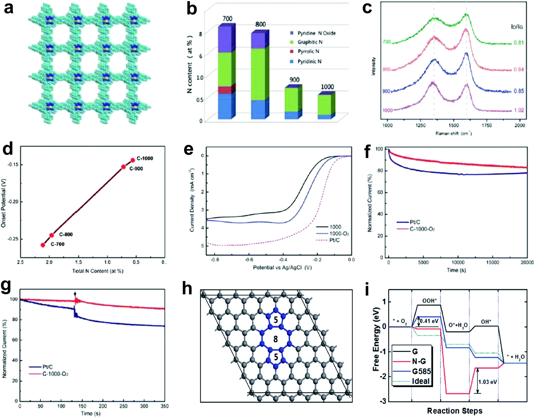 | ||
| Fig. 2 Investigations of N-ORR activity relationship and the corresponding defect mechanism study. (a) Schematic of a N-enriched porous aromatic framework material (PAF-40), which is a precursor to synthesize defective carbon. (b–d) Relative atomic percentage of different nitrogen bonding states, Raman spectra and ORR onset potentials in prepared defective carbons treated under a temperate range (700 °C, 800 °C, 900 °C and 1000 °C). (e) ORR polarization curves of C-1000, C-1000-O2 and Pt/C recorded at room temperature in an O2-saturated 0.1 M KOH electrolyte. (f and g) Stability test and methanol tolerance test of C-1000-O2 and Pt/C. (h) Atomic structure of G585 defect in graphene. (i) N-Doped graphene (N-G), graphene with G585 defects (G585) and an ideal catalyst (Ideal) for ORR at the equilibrium potentials. Reproduced with permission.48 Copyright 2015, RSC. | ||
2.2 ORR activity in defective carbons
To completely eliminate the N effect in defective carbon-based materials for electrocatalysis, our group subsequently carbonized a Zn-metal organic framework material (IRMOF-8) by removing all of the Zn to yield a derived carbon containing only C and O, without any active doping elements (e.g. N, B, P or S) as determined by X-ray photoelectron spectroscopy (XPS).49Fig. 3a presents the schematic structural changes of IRMOF-8 with carbonization to yield the non-doped porous carbon (PC) as a black soot-like material, which involved a similar method to processes reported previously.88,89 The Raman spectrum (Fig. 3b) illustrates the disordered structure and the multilayer/graphitic stacked domains in the derived carbon framework. Importantly, the successful synthesis of non-doped porous carbon (PC) was firmly evidenced by XPS spectra without the presence of Zn 2p and N 1s traces (Fig. 3c–e). To experimentally authenticate the proof-of-concept of the defect catalytic mechanism in ORR, LSV measurements were carried out. As expected, the derived pure defective carbon exhibited excellent ORR activity (Fig. 3f), in contrast to the requirements of the heteroatom-doping mechanism (that is, no doping, no activity). Moreover, this defective carbon material demonstrated improved molecular selectivity and stability as compared to the commercial Pt/C catalyst (Fig. 3g and h). | ||
| Fig. 3 Investigation of the ORR activity in non-doped porous carbon (PC) derived from IRMOF-8 carbonization. (a) Schematic structural changes of IRMOF-8 with carbonization to yield non-doped PC. (b–e) Raman spectrum, XPS survey spectrum and high resolution XPS spectra (Zn 2p and N 1s) of non-doped PC, respectively. (f) LSV curves at 1600 rpm of non-doped PC, Pt/C and XC-72 catalysts. (g) Chronoamperometric stability and methanol tolerance tests of non-doped PC and Pt/C. (h) CV stability test of non-doped PC up to 500 cycles with a scanned rate of 50 mV s−1. Reproduced with permission.49 Copyright 2016, RSC. | ||
Our preceding findings demonstrate the critical role of the defects of carbon, that is, carbon materials with more defects have better activities than pristine carbon (and even compared to doped carbons).48,49 Researchers from other groups have also started to devote great efforts to prepare carbon-based materials with a large number of intrinsic/induced defects. Almost simultaneously, Xia and co-workers theoretically studied the effect of point- and line-defects in graphene on the catalytic activities using density functional theory (DFT) methods.88 In particular, they found that a pentagon ring at the zigzag edge and the line-defect pentagon–pentagon–octagon chain significantly modify local charge/spin polarization at the defective sites, leading to catalysis of the ORR (Fig. 4a and b).90 They further claimed that the reaction energy barriers of the four-electron-transfer pathway on defective graphene are comparable to that of platinum.90 Experimentally, Hu and co-workers used purely defective carbon nanocages (CNCs) with a high specific surface area (SSA) containing abundant holes and edges but without any dopants to address the influence of intrinsic carbon defects on ORR activity (Fig. 4c–e).53 It is noteworthy that the CNC700 with the highest defect level (ID/IG ratio in the Raman spectrum of 2.29) exhibited the best ORR activity with a high onset potential about 0.11 V vs. normal hydrogen electrode (NHE) in 0.1 M KOH (Fig. 4e). The electron-transfer number (n) and the corresponding peroxide species (HO2−) were further calculated to be ∼2.90 ± 0.10 and ∼55%, respectively, suggesting a mixed two-electron and four-electron process. Remarkably, the comparison experiments showed that the defective CNC700 was even superior to N/B-doped CNTs in ORR, which clearly indicated the significant contribution of the carbon defects in electrocatalysis. DFT calculations indicated that the pentagon and zigzag edge defects were responsible for the high ORR activity in defective CNCs, which could be attributed to the redistributed electronic structures from unpaired π electrons at carbon defects sites (Fig. 4f).53
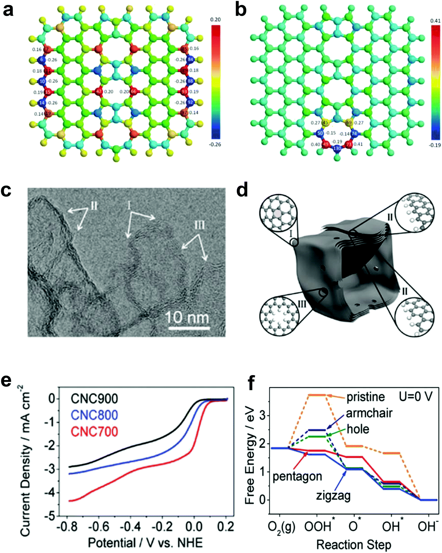 | ||
| Fig. 4 (a) Charge and (b) spin density distributions on the graphene cluster containing a line defect with an odd number of octagon and fused pentagon carbon rings. Reproduced with permission.90 Copyright 2015, Royal Society of Chemistry. (c) HRTEM image of CNC700. (d) Schematic structural character of the carbon nanocages. I, II and III in the highlighted diagrams represent three typical defect locations. (e) ORR performances of CNC700, CNC800 and CNC900 in O2-saturated 0.1 M KOH. (f) Free energy diagrams for ORR activities of different defects in CNC700. Reproduced with permission.53 Copyright 2015, American Chemical Society. | ||
Alternatively, Wang and co-workers used an Ar plasma method to etch the surface of graphene and carbon nanotubes (CNTs) to expose plenty of defects on the perfect carbon lattice (Fig. 5a).54 TEM images illustrated that massive holes and cracks existed in Ar plasma-treated defective graphene and CNTs, respectively (Fig. 5b and c), suggesting the level of defects was increased due to the additional exposed edges. The ORR performances of the Ar plasma-treated defective graphene and CNTs were both enhanced as compared to the pristine counterparts (Fig. 5d and e), which could be ascribed to the formed defects acting as the active sites for ORR electrolysis. These findings on defective carbons may push us to reconsider the origin of the improved ORR activity for carbon-based materials.54
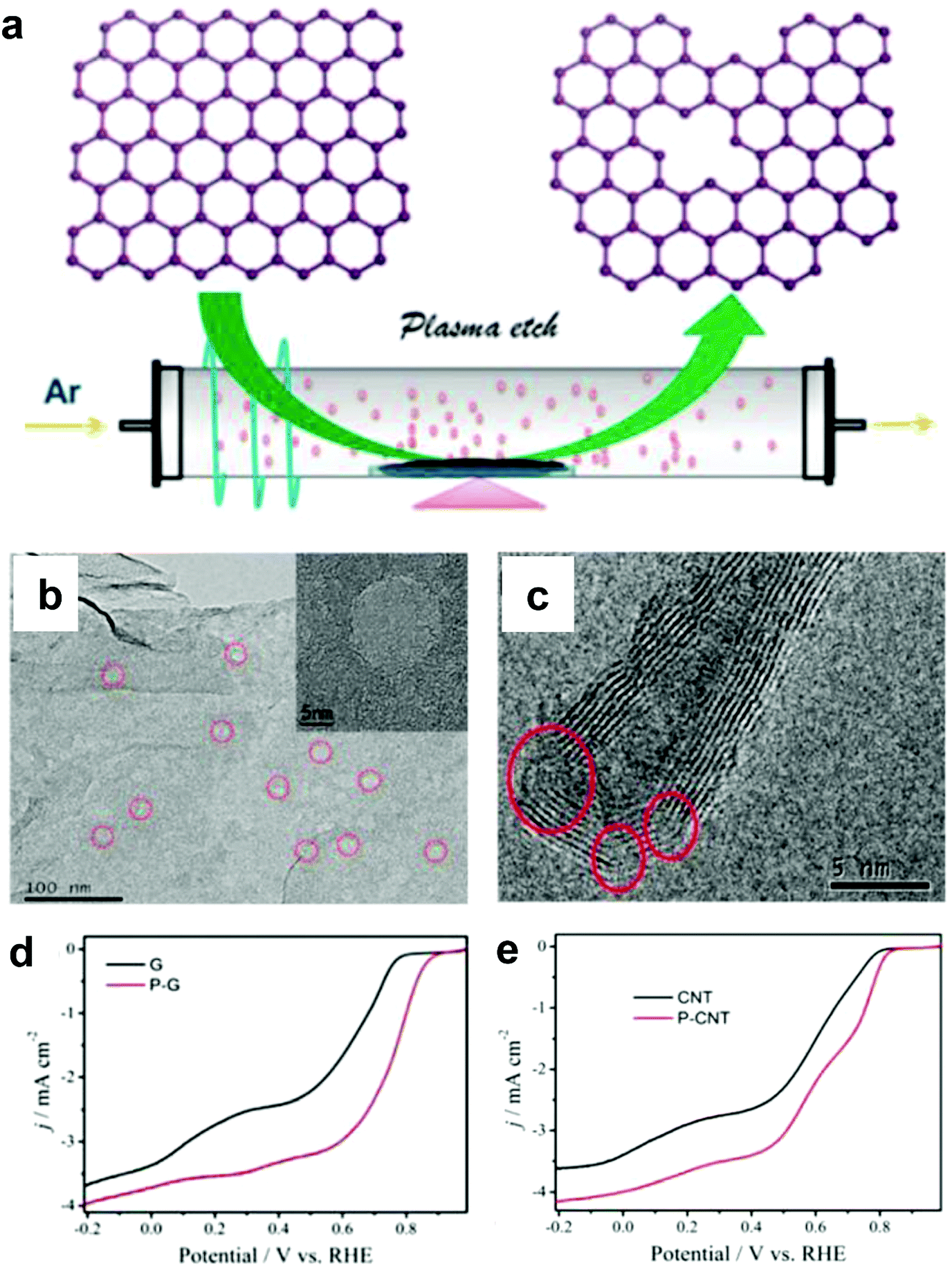 | ||
| Fig. 5 (a) Illustration of the preparation of defective graphene by Ar plasma etching. TEM images of (b) Ar plasma-treated graphene and (c) carbon nanotube. (d) ORR performances of pristine and Ar plasma-treated defective graphenes in O2-saturated 0.1 M KOH. (e) ORR performances of pristine and Ar plasma-treated defective carbon nanotubes in O2-saturated 0.1 M KOH. Reproduced with permission.54 Copyright 2015, RSC. | ||
2.3 Defective graphene: defect mechanism for ORR, OER and HER
As discussed in Sections 2.1 and 2.2, a defect catalytic mechanism in ORR was proved by both experimental results and theoretical calculations. However, currently a few issues still need to be addressed for understanding the defect catalytic mechanism: (i) the topological defects, such as in PAF/MOF-derived carbons, have not been directly observed due to the resulting complex 3D structures obtained after carbonization;48,49 (ii) according to theoretical correlations of the carbon defect types and electronic structures, carbon defects can be analogously categorized into n-type and p-type, leading to a potential enhancement in electrochemical reductions (e.g. ORR and HER) and oxidation reactions (e.g. OER), respectively.91–93 Although defect catalysis has been explored in ORR, whether defective carbons possessing multi-types of defects are also functional for other electrochemical reactions, such as OER and HER, is still unknown.To tackle these issues, our group developed a 2D defective graphene (DG) obtained via a facile nitrogen removal procedure from a N-doped precursor (Fig. 6a).50 As the synthetic process may create different types of defects, aberration-corrected high-resolution transmission electron microscopy (AC-HRTEM) was used to actually visualize the defects regions of the material. Strong lattice disorder could be witnessed near the edge of the graphene sheet (Fig. 6b), which could be attributed to the various structural defects marked in the image. Afterwards, the evaluation of the electrocatalytic activities demonstrated that the DG material was functional not only for the ORR but also for the OER and HER, and the activity of the material was significantly higher than that of the parent NG for all three basic electrochemical reactions (Fig. 6c–f). To gain an in-depth insight into the underlying catalytic mechanisms, density function theory (DFT) calculations of the reaction energy profiles towards HER, OER and ORR were conducted. Three computational models were built based on the AC-HRTEM observed types of defects in the DG material, i.e. edge pentagon, D585 and D7557 (the combination of carbon rings with heptagon–pentagon–pentagon–heptagon) (Fig. 6g–i). Remarkably, the energy profiles for ORR, OER and HER (Fig. 6j–l) reveal that active sites for different electrochemical reactions are induced by specific defect types due to a particular desired reactant binding energy for each electrochemical reaction. It should be noted that in all cases, the defective graphene was superior to N-doped graphene for ORR, HER and OER. It is speculated that the activity of N-doped graphene was also from the vacancy type defects as the doping process was dynamic with some N release as well to create the vacancies. Due to the much lower density of available vacancies, the activity was lower.
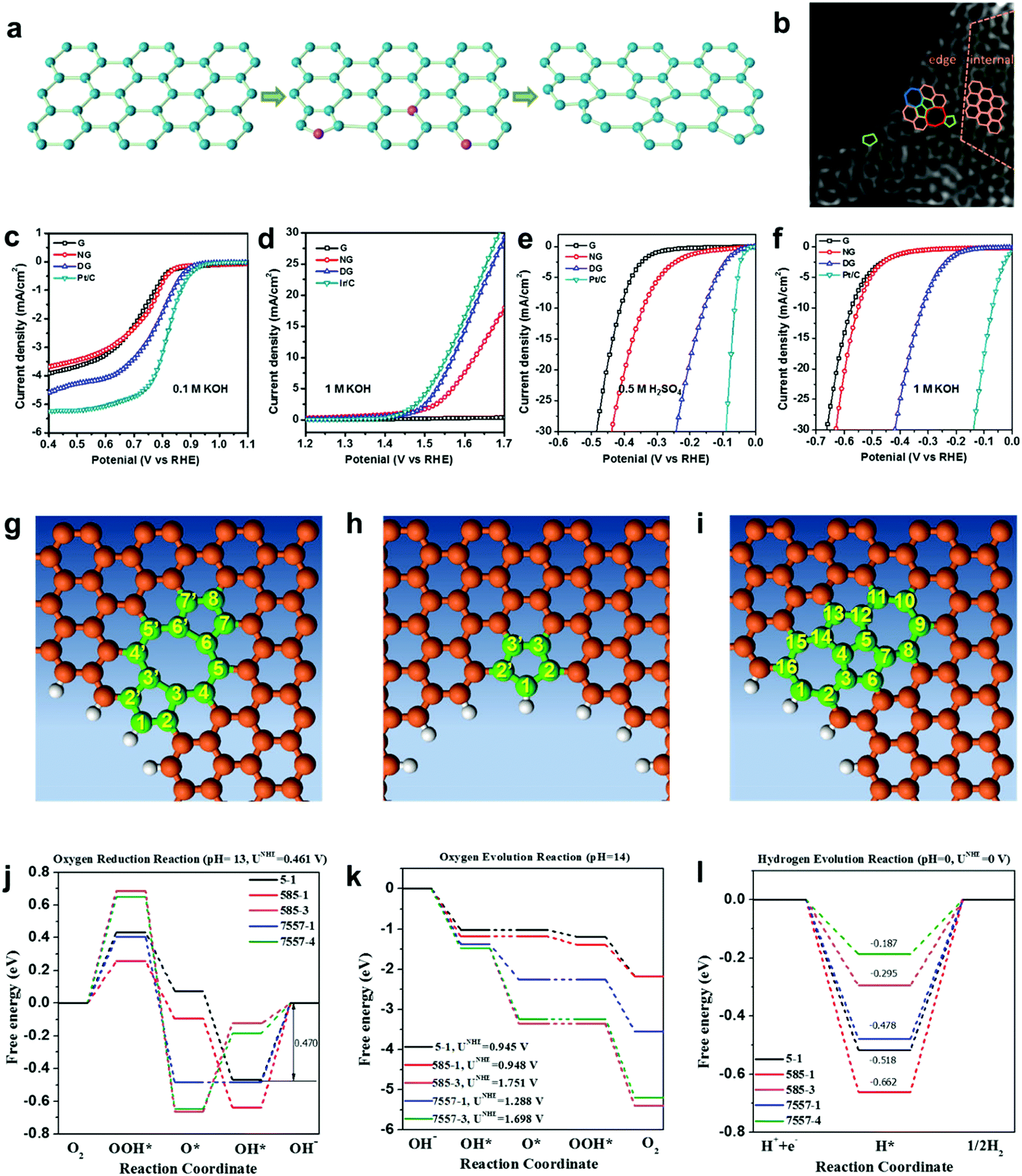 | ||
| Fig. 6 (a) Schematic of the formation of DG. (b) HAADF image of DG with an acceleration voltage of 80 kV. Hexagons, pentagons, heptagons and octagons are labelled in orange, green, blue and red, respectively. (c–f) Linear sweep voltammetry curves of the pristine graphene, NG and DG. (c) Oxygen reduction reaction. (d) Oxygen evolution reaction. (e) Hydrogen evolution reaction in acid and (f) alkaline solution, respectively. (g–l) Mechanism study of trifunctionality in defective graphene for ORR, OER and HER. (g) D585 defect. (h) Edge pentagon. (i) D7557 defect. (j–l) Schematic energy profiles for the ORR pathway, the OER pathway and the HER pathway on defective graphene in alkaline/acidic media. To improve legibility, “OH−” is omitted from the labels. Reproduced with permission.50 Copyright 2016, Wiley-VCH. | ||
Recently, Zhang and co-workers demonstrated an enhancement in reaction pathway of ORR/OER through both experimental electrochemical evaluation and theoretical calculations by using a unique nitrogen-doped (7.60 atom%) and edge-rich 3D graphene model system obtained via the carbonization (950 °C under Ar) of sticky rice as the carbon precursor, melamine as the nitrogen source, with Mg(OH)2 as the template (Fig. 7a–c).51 Their calculation results revealed that a nitrogen-free configuration with adjacent pentagon and heptagon carbon rings exhibited the lowest overpotential for both ORR and OER at the peak of the volcano plot (Fig. 7d and e), which strongly supports the aforementioned defect mechanism.50 Alternatively, Tian and co-workers also developed a 3D porous graphene possessing high-level N-doping and rich structural defects (denoted as 3DNG-P) by a self-assembly hydrothermal approach and subsequent Ar plasma treatment.55 They found the defective 3DNG-P could significantly improve the HER activity (achieving an overpotential of 128 mV at 10 mA cm−2) as compared to the sole N-doped counterpart, which was even comparable to the values from some of the state-of-the-art transition-metal-based catalysts in HER.55
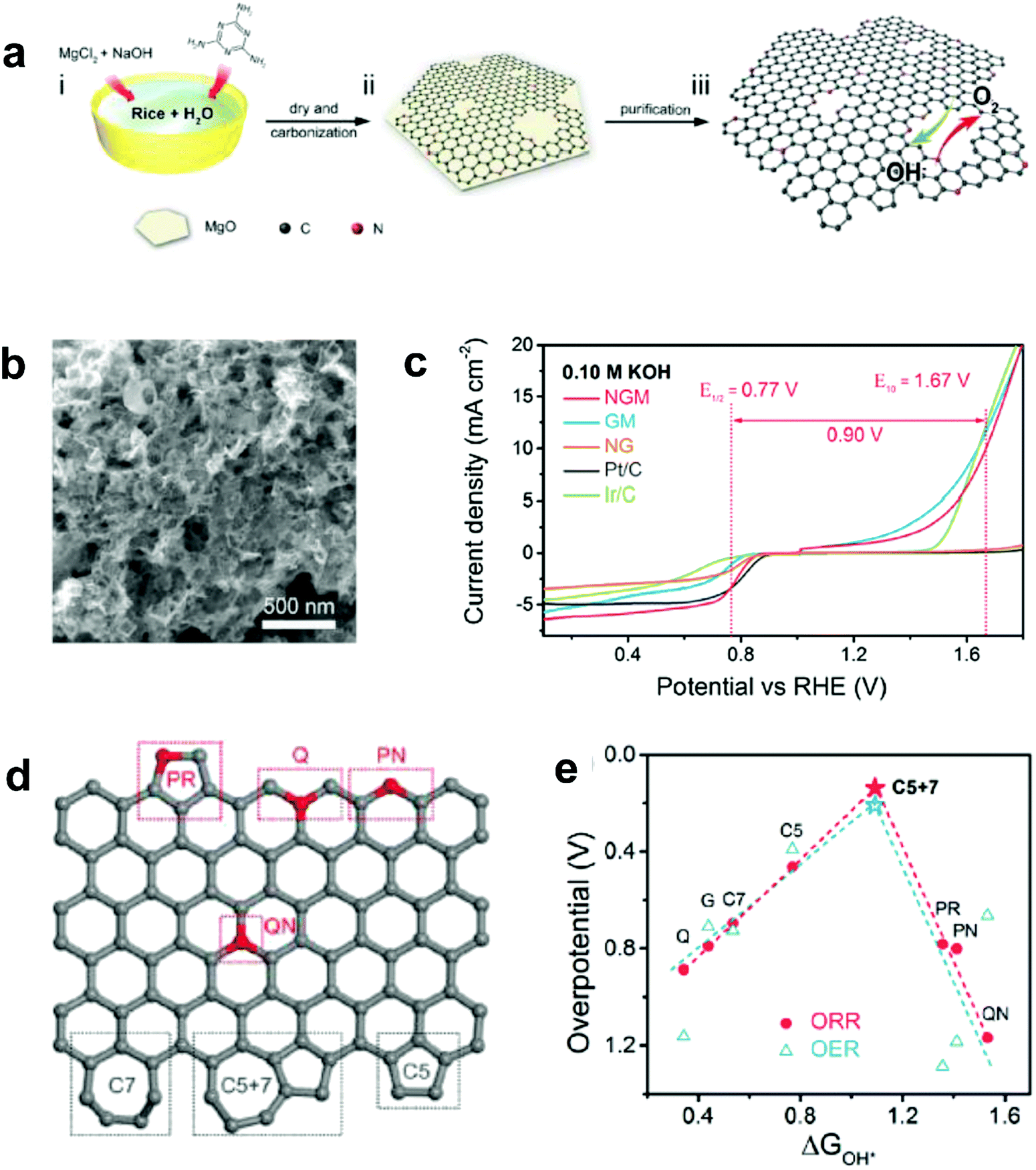 | ||
| Fig. 7 (a) Schematic of the fabrication of a unique nitrogen-doped and edge-rich 3D graphene (nitrogen-doped mesh, denotes as NGM). (b) TEM image showing the interconnected nanoplates of NGM. (c) ORR/OER bifunctional activities of NGM, GM, NG, commercial Pt/C and Ir/C catalysts. (d) A schematic graphene nanoribbon with different kinds of N-doping or topological defects (PR: pyrrolic nitrogen; PN: pyridinic nitrogen; Q: quaternary nitrogen on the edge; QN: quaternary nitrogen in the bulk phase; C5: five-carbon ring; C7: seven-carbon ring; C5 + 7: five-carbon ring adjacent to seven-carbon ring). (e) ORR and OER volcano plots of the overpotential versus adsorption energy of OH*, indicating C5 + 7 as the optimal active site for both ORR and OER electrocatalysis. Reproduced with permission.51 Copyright 2016, Wiley-VCH. | ||
Most recently, Yu and co-workers successfully introduced N defects into g-C3N4via an alkali-assisted (e.g. KOH) strategy during the thermal polymerization of nitrogen-rich precursors (e.g. urea).56 They found that the N defect density increased with the ascending amount of KOH addition, as evidenced by the appearance of cyano groups (–C![[triple bond, length as m-dash]](https://www.rsc.org/images/entities/char_e002.gif) N) and the diminishing peak of N–H bond in the FTIR spectra (Fig. 8a). UV-vis diffuse reflectance spectra (DRS) revealed that a progressive red-shift in the absorption edge was achieved with increasing the KOH addition amount, indicating that N defects may induce a narrowed bandgap of the as-prepared g-C3Nx samples (Fig. 8b). To better unveil the correlation between the N defects and the narrowed bandgaps of g-C3Nx samples, the author calculated the band structure and partial density of states (PDOS) for both defective g-C3Nx and pristine g-C3N4via density functional theory (DFT) (Fig. 8c–h).56 The results revealed that the bandgap energy of defective g-C3Nx decreased from 2.67 to 2.17 eV after introducing defects, which was attributed to the altered C 2p and N 2p orbitals in the conductive band of defective g-C3Nx as compared to those of the pristine g-C3N4. All these experimental and theoretical results demonstrated that the defects in carbon-based materials play a vital role in (photo)-electrocatalysis, which highlights the need to unveil their catalytic mechanism urgently.
N) and the diminishing peak of N–H bond in the FTIR spectra (Fig. 8a). UV-vis diffuse reflectance spectra (DRS) revealed that a progressive red-shift in the absorption edge was achieved with increasing the KOH addition amount, indicating that N defects may induce a narrowed bandgap of the as-prepared g-C3Nx samples (Fig. 8b). To better unveil the correlation between the N defects and the narrowed bandgaps of g-C3Nx samples, the author calculated the band structure and partial density of states (PDOS) for both defective g-C3Nx and pristine g-C3N4via density functional theory (DFT) (Fig. 8c–h).56 The results revealed that the bandgap energy of defective g-C3Nx decreased from 2.67 to 2.17 eV after introducing defects, which was attributed to the altered C 2p and N 2p orbitals in the conductive band of defective g-C3Nx as compared to those of the pristine g-C3N4. All these experimental and theoretical results demonstrated that the defects in carbon-based materials play a vital role in (photo)-electrocatalysis, which highlights the need to unveil their catalytic mechanism urgently.
 | ||
| Fig. 8 (a) FTIR spectra of g-C3N4 and g-C3Nx with proposed structure changes in heptazine units before and after introducing cyano groups. (b) UV-vis diffuse reflectance spectra (DRS) for g-C3N4 and g-C3Nx prepared using urea as a precursor and different amounts of KOH (ranging from 0 to 1.0 g). (c and f) Structure models of g-C3N4 and g-C3Nx with N defects (including –CN group and N vacancy). (d and g) Calculated band structures. (e and h) Corresponding partial density of states (PDOS) for g-C3N4 and g-C3Nx, respectively.56 Copyright 2017, Wiley-VCH. | ||
2.4 Defects enabling activated carbon to be “active”
The research above marked the initiation of the defect mechanism. Besides the fundamental studies, one of our motivations was to produce efficient electrocatalysts for industrial applications in fuel cells and rechargeable metal–air batteries by a scalable and facile method. Generally, carbon materials, such as activated carbon (AC), are only used as a support for the catalysts because of their low catalytic activity; for example, AC is not efficiently active for the electrochemical reactions, even when doped with nitrogen.94 Due to the merits of AC in aspects of its low cost and facile large-scale production, if it can become active for electrocatalysis by applying the proposed defect mechanism, this would represent a remarkable breakthrough to accelerate the practical applications of fuel cells.Fig. 9a presents the schematic of the synthesis of defective activated carbon (D-AC) with unique defects for enhancing ORR performance by an easy N-doping and removal approach.52 It can be seen that the resultant D-AC sample shows comparable ORR to the commercial Pt/C in an alkaline solution (Fig. 9b), and it is more stable than the Pt/C (Fig. 9c). Furthermore, the rotation ring-disc electrode (RRDE) test (Fig. 9d) illustrates the low current density of the ring disc in D-AC, indicating that the D-AC catalyst dominantly produces H2O instead of H2O2, which can be attributed to the high electron-transfer number of 3.6 in D-AC (close to 3.9 in commercial Pt/C) for ORR.52
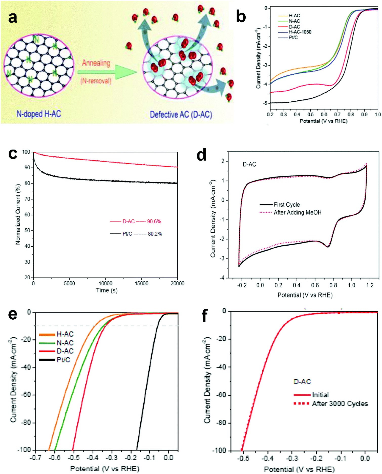 | ||
| Fig. 9 (a) Schematic of the formation of defective activated carbon (D-AC) for enhancing ORR performance. (b) LSV curves of the H-AC, N-AC, D-AC and Pt/C measured at the rotation speed of 1600 rpm in O2-saturated 0.1 M KOH solution. (c) Amperometric i–t curves of the D-AC and Pt/C. (d) Rotation ring-disk electrode voltammogram of the H-AC, D-AC and Pt/C in O2-saturated 0.1 M KOH solution at 1600 rpm. (e) HER polarization curves of the H-AC, N-AC, D-AC and Pt/C measured at the scan rate of 10 mV s−1 in 0.5 M H2SO4 solution. (f) HER polarization curves recorded for the D-AC before and after 3000 cycles of CV scan under acidic conditions. Reproduced with permission.52 Copyright 2016, RSC. | ||
Besides, D-AC also shows improved HER activity (Fig. 9e) and good cycling stability for the HER (Fig. 9f). As can be seen, the non-active activated carbon can become an ideal catalyst for both the ORR and HER after a simple treatment based on the proposed defect mechanism. Apparently, this synthetic approach is possible for large-scale production due to the low cost of the raw material, suggesting that D-AC has great potential for practical fuel cell and water-splitting applications.
2.5 Coupling of defective carbons with non-noble metal species
In Section 2.4, we presented a kind of defective carbon (D-AC), which could be prepared from cost-effective activated carbon. Although the ORR performance of the D-AC is among the best of the carbon-based counterparts, it needs to be further enhanced, since it is still less active than the commercial Pt/C. It is reported that the Mn–Co spinel could promote the ORR effectively,95–97 and as a carbon support is also crucial to the ORR catalysts, so we used the prepared D-AC as a support and loaded a very low amount of MnCo2O4 spinel to further increase the ORR activity of the D-AC.57 The D-AC supported MnCo2O4 sample (denoted as D-AC@2Mn–4Co) showed excellent ORR activity (comparable to commercial Pt/C catalyst), but the total metal content was lower than that of the Pt/C (13.4 vs. 20 wt%), making it more appealing to practical fuel cell applications. Meanwhile, the D-AC@2Mn–4Co showed much higher durability than the Pt/C as well as resistance to the methanol crossover effect, implying its promising utilization for direct methanol fuel cells. We found that both the unique defects in the D-AC and the loaded MnCo2O4 spinel were essential to the outstanding ORR performance of the D-AC@2Mn–4Co, and that the newly formed C–O–Mn/Co chemical bonds may play an important role in decreasing the reaction barrier and increasing the electron-transfer efficiency during the ORR process. Very recently, we demonstrated a heterostructured NiFe LDH-NS@DG10 hybrid by coupling an exfoliated Ni–Fe layered double hydroxide (LDH) nanosheet (NS) and defective graphene (DG) as a bifunctional electrocatalyst for both OER and HER (Fig. 10a and b).58 Impressively, this catalyst exhibited high electrocatalytic overall water splitting (20 mA cm−2 at 1.5 V) superior to those of NiFe LDH-NS@graphene (NG and G) counterparts (Fig. 10c and inset). It is remarkable that NiFe LDH-NS@DG ranked the best as compared to other non-noble metal bifunctional catalysts for overall alkaline water splitting (Fig. 10d), which could be easily driven by a 1.5 V solar panel (Fig. 10e). The simulation results further revealed that the formed heterostrucutre could efficiently enhance the charge separation and redistribution (electron-rich zones on carbon defect sites and electron-deficient zones on Ni–Fe LDH-NS) (Fig. 10f and g), thus facilitating the HER and OER conducted on defective graphene and NiFe LDH-NS, respectively (Fig. 10h).58 Subsequently, Zhang and co-workers also demonstrated the direct utilization of defects in carbon-based materials to create atomic Co–Nx–C coordination structures, which could serve as bifunctional active sites for both ORR and OER.59 Meanwhile, Zhang et al. directly identified the coordination structure of atomic Ni trapped in graphene defects by using probe-corrected TEM, and further revealed that different integrated coordination structures (atomic Ni at various carbon defects) may be the specific active sites for OER and HER, respectively.60 For commercialization purpose, Liu et al. developed a controllable and scalable synthetic strategy of such defective carbons from cheap and earth-abundant biowaste resources (e.g. seaweed), and the derived carbon-based catalyst exhibited efficient performance in both ORR and OER.61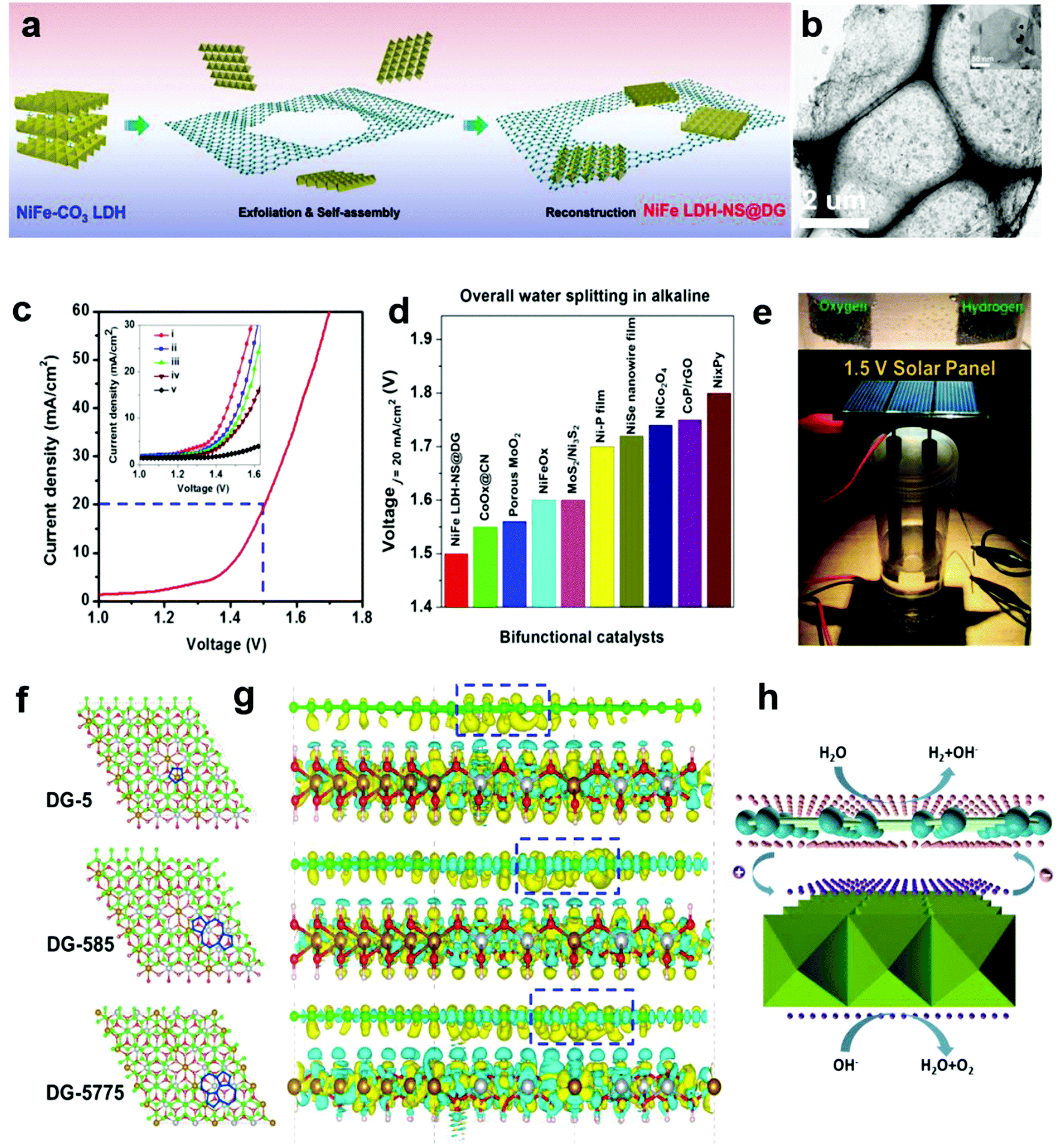 | ||
| Fig. 10 (a) Schematic illustration of the preparation of a NiFe LDH-NS@DG nanocomposite and (b) its TEM images with low and high (inset) magnifications. (c) Linear sweeping voltammetry curve of NiFe LDH-NS@DG10 as an OER and HER bifunctional catalyst in 1 M KOH for overall water splitting (both loaded into Ni foam at a loading of 2 mg cm−2), with the inset showing a comparison of different catalysts, including (i) NiFe LDH-NS@DG10 with 2 mg cm−2 loading; (ii) NiFe LDH-NS@DG10 with 1 mg cm−2 loading; (iii) NiFe LDH-NS@NG10 with 2 mg cm−2 loading; (iv) NiFe LDH-NS@ G10 with 2 mg cm−2 loading; (v) bare Ni foam electrode. (d) Comparison of the required voltage at a current density of 20 mA cm−2 for the NiFe LDH-NS@DG catalyst with other state-of-the-art noble-metal-free bifunctional catalysts. (e) Demonstration of a solar-power-assisted water-splitting device with a voltage of 1.5 V. (f and g) DFT calculation studies of the Ni–Fe LDH-NS@DG (DG-5, DG-585, or DG-7557)-based composite. Yellow and cyan isosurfaces represent charge accumulation and depletion in the 3D space with an isosurface value of 0.002 e Å−3. (h) Schematic of the probable electrocatalytic mechanism of Ni–Fe LDH-NS@DG for HER and OER based on the DFT calculation results. Reproduced with permission.58 Copyright 2017, Wiley-VCH. | ||
3. Mechanistic understanding on electronic structures of defective carbon-based materials and electrocatalysis
3.1 Origin of carbon defect catalysis
In 2009, a new class of catalyst based on heteroatom-doped carbon materials was discovered, with an aim to replace the platinum-based catalysts in fuel cells. Specifically, it was reported that nitrogen-doped (N-doped) carbon nanotubes could act as efficient and robust catalysts in ORR.27 Since then, massive efforts have been focused on the tailoring of carbon-based electrochemical catalysts by heteroatom-doping/co-doping engineering (e.g. N, B, P and S).4,5,30–34,62,63,98 Recently, these heteroatom-doped/co-doped carbon-based catalysts have also been demonstrated to be efficient for OER and HER.5,8,30–34,98 Despite great progress being made on this topic, the origin of the electrocatalytic activity of heteroatom-doped carbon is still far from clarified, which is actually the current hot research focus in this field.55,99–104 For instance, in N-doped carbon-based catalysts, it is still controversial whether the pyridinic or graphitic nitrogen is mainly responsible for the ORR. On the other hand, a large number of intrinsic structural and edge defects exist in the doped sp2 carbon materials for the accommodation of dopants, implying that the local electronic structures may be significantly tuned by the synergistic effect of both dopants and defects, which leads to the generation of active sites for specific electrochemical reactions.105 Therefore, the electrocatalytic activities of doped carbon materials should originate at least partially from the intrinsic defects. However, the research and knowledge of defect-induced electrocatalysis is still at the very early stage to date, and requires urgent development.Defects in carbon materials, especially vacant defects (e.g. pentagon, heptagon and octagon carbon rings), have been found to be capable of modifying the local atomic structure and tailoring its electronic environment.91–93 For instance, it is theoretically predicted that a pentagon carbon ring will induce acceptor-like electronic states near the valence band, whereas a heptagon carbon ring will induce donor-like electronic states near the conduction band.93 Intuitively, introducing topological defects into carbon-based materials could break the delocalization orbitals of sp2 carbon to create charged sites that may be favourable for the ORR, OER and HER.
3.2 Correlations of carbon defect types and electronic structures
Generally, in perfect graphene, the Fermi level (EF) coincides well with the Dirac point, and thus both the π and π* bands near EF are doubly degenerate. Interestingly, a recent theoretical study suggested that the electronic structures of graphene can be tuned by different local defects.93 Specifically, three typical defects in graphene with associated electronic structures were investigated, as shown in Fig. 11. D59 (adjacent hexagonal carbon rings lacking one carbon atom) and D585 are known as monovacancy (MV) defects (Fig. 11a) and divacancy (DV) defects (Fig. 11e), respectively, while D5775 (the combination of carbon rings with pentagon–heptagon–heptagon–pentagon) is a Stone–Wales (SW) defect associated with the reconstruction of a graphenic lattice but without the removal of carbon atoms (Fig. 11i). In Fig. 11b, the band structure of graphene with MV presents that EF is below the Dirac point, indicating that MV acts as a hole dopant. Furthermore, the partial density of states (PDOS) results of MV (Fig. 11c) showed that C1, C3, C5 and C7 had high defect π state densities derived from Pz orbitals around EF, where the active sites for electrocatalytic oxidation reactions should be. This result is well consistent with the simulated scanning tunnelling microscopy (STM) image for MV (Fig. 11d), which shows a slightly brighter domain around the MV under negative bias voltages than that under positive bias voltages, indicating p-type doping behaviour for the MV defect. In contrast, the band structures and PDOS for graphene with DV (Fig. 11f and g) and SW defects (Fig. 11j and k) presented that the defect π states were both located above EF, suggesting n-type doping behaviour in the DV and SW defects, which appeals to electrocatalytic reduction reactions. As the defect level is unoccupied in DV and SW, the STM images with positive bias voltages have a much brighter contrast than those with negative bias voltages (Fig. 11h and l), which is distinctly different from the case of MV, where the defect π level is mostly below EF.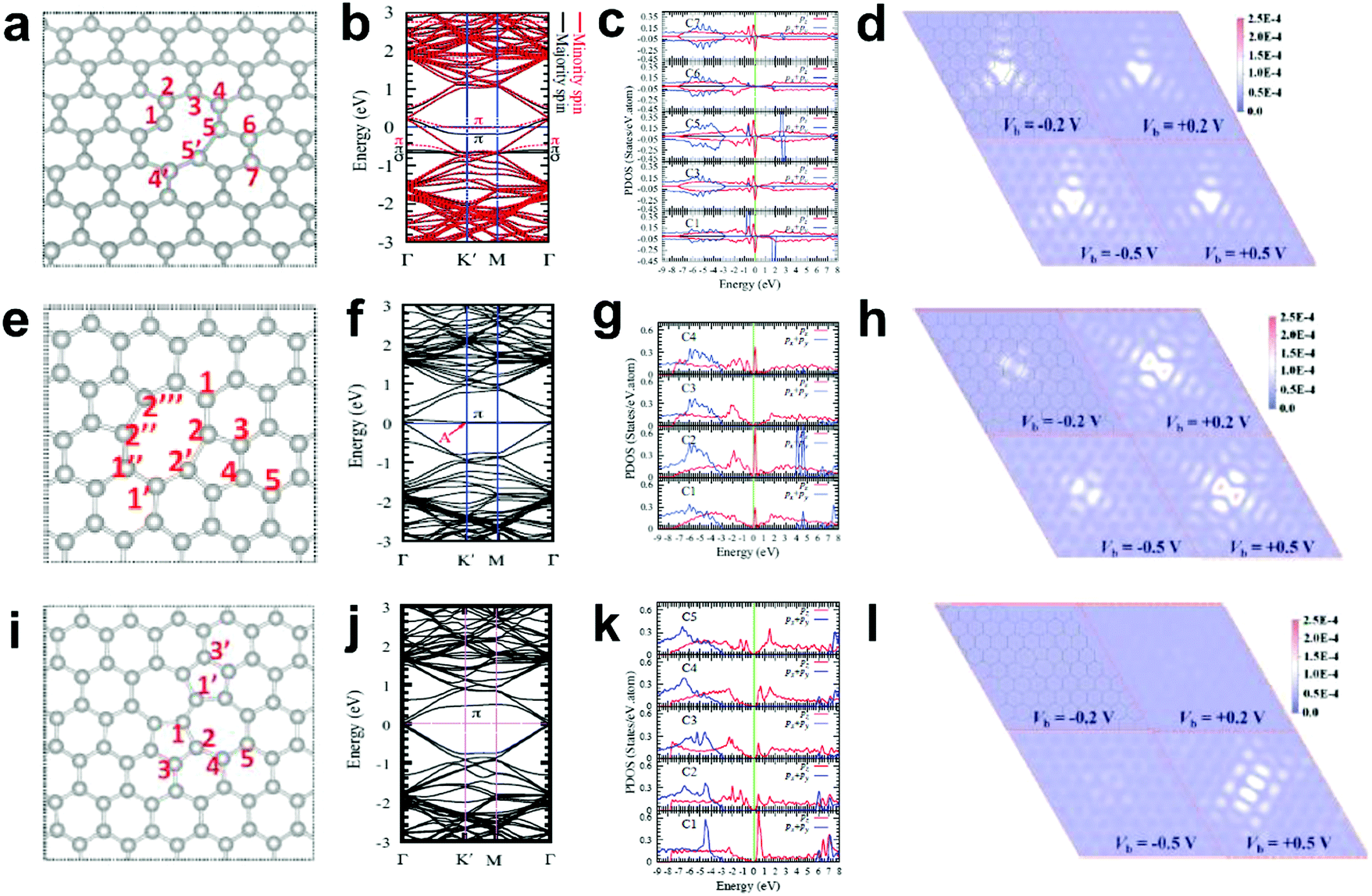 | ||
| Fig. 11 Correlations of carbon defect types and electronic structures. (a, e and i) Atomic structures of D59 (monovacancy, MV defect), D585 (divacancy, DV defect) and D5775 (Stone–Wales, SW defect). (b, f and j) Band structures of graphene with MV, DV and SW. (c, g and k) The partial density of states (PDOS) around the defect region of MV, DV and SW. (d, h and l) Simulated scanning tunnelling microscopy (STM) images for MV, DV and SW. Reproduced with permission.93 Copyright 2013, American Physical Society. | ||
3.3 Quantifying carbon defects for electrocatalysis
Quantifying defects in carbon-based systems, including in a large family of sp2 carbon structures, is paramount to gain insights into their underlying mechanism for electrochemical applications.106–108 Recently, extensive efforts have been made to study the relationship between the defects and disorder using Raman spectroscopy for nanographites,109,110 amorphous carbons,111,112 carbon nanotubes113 and graphene.114–116 A quantitative formula was proposed to correlate the mean distance between two adjacent defects (LD, nm) in graphene with the intensity ratio of the D band over G band (ID/IG) in the Raman spectra: | (1) |
 | (2) |
 | (3) |
The defect density (nD) can be calculated by nD (cm−2) = 1014/(πLD2); therefore, eqn (3) becomes:
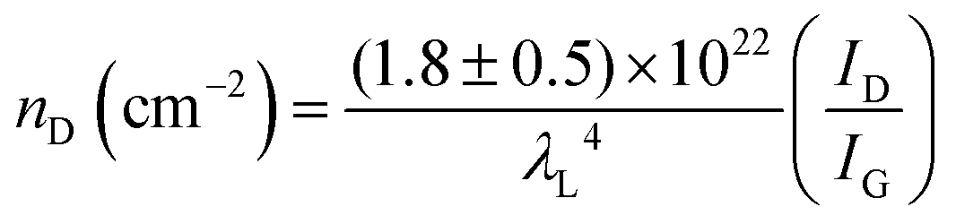 | (4) |
Therefore, we were able to deduce the defect densities of our developed defective carbons from ID/IG by using eqn (4), and the results are summarized in Table 1. By comparing the calculated defect densities and observed electrochemical activities in ORR/OER/HER, it was indicated that we had succeeded in controlling different the defect densities in our developed defective carbons, which has a positive correlation to the catalytic performance in ORR/OER/HER.
| Samples | I D /I G | n D (cm−2) | ORR E1/2a (V vs. RHE) | OER Ej=10b (V vs. RHE) | HER Ej=10b (V vs. RHE) | Ref. |
|---|---|---|---|---|---|---|
| a E 1/2 is the ORR half-wave potential. b E j=10 is the OER/HER potential obtained at the current density of 10 mA cm−2. ORR was conducted in 0.1 M KOH, OER was conducted in 1 M KOH, and HER was conducted in 0.5 M H2SO4. | ||||||
| PAF-C-700 | 0.81 | 2.28 × 10¹² | 0.56 | — | — | 48 |
| PAF-C-800 | 0.84 | 2.38 × 10¹² | 0.57 | — | — | 48 |
| PAF-C-900 | 0.85 | 2.41 × 10¹² | 0.68 | — | — | 48 |
| PAF-C-1000 | 1.02 | 3.00 × 10¹² | 0.69 | — | — | 48 |
| PC-I8-950 | 0.97 | 2.82 × 10¹² | 0.79 | — | — | 49 |
| G | 0.89 | 2.55 × 10¹² | 0.71 | — | −0.42 | 50 |
| NG | 1.06 | 3.15 × 10¹² | 0.75 | 1.63 | −0.35 | 50 |
| DG | 1.13 | 3.42 × 10¹² | 0.76 | 1.57 | −0.15 | 50 |
| H-AC | 0.89 | 2.55 × 10¹² | 0.71 | — | −0.63 | 52 |
| N-AC | 0.92 | 2.65 × 10¹² | 0.71 | — | −0.60 | 52 |
| D-AC | 0.96 | 2.79 × 10¹² | 0.77 | — | −0.51 | 52 |
Interestingly, it is notable that PC-I8-950 (no heteroatom doping) with a low defect density (2.82 × 1012 cm−2) exhibited a better ORR activity than that of PAF-C-1000 with high defect density (3.00 × 1012 cm−2), suggesting the optimal electrochemical activity may need to be synergistically tuned by the defect density and other factors, such as the conductivity and nanostructure.
To further investigate the influence of the carbon defect density on the electrochemical activity, a series of Ar+-radiated graphene samples (eliminating the doping effect) with precise control of the defect densities were characterized by Raman spectroscopy and scanning electrochemical microscopy (SECM), as shown in Fig. 12.118Fig. 12a presents Raman mapping of the D band of the defective graphene (from pattern B to H) and pristine graphene (pattern A), which shows that the intensity of the D band increases from pattern B to E, followed by the intensity decreasing from pattern F to H. This result is simultaneously evidenced by the corresponding Raman spectra in Fig. 12b. Subsequently, to evaluate the electrochemical activities of the above defective graphene samples, SECM was applied to determine heterogeneous electron-transfer (HET) rates. As shown in Fig. 12c, it was observed that with increasing the defect density, the tip current firstly increases (from pattern B to H) then decreases (pattern G to H) to even below that of the pristine graphene (pattern A). The two-stage SECM patterns were in agreement with the Raman D-band mapping results, which indicates the electrochemical activity of single-layer graphene relies on its defect density. To gain an insight into the defects in graphene, three microscopic models in different defect density ranges (the red zone presents the structurally disordered area, and the yellow zone presents the electronically activated area) were established (Fig. 12d–f). In the case of the low defect density (Fig. 12d), the carbon defects exist independently and sparsely. With the increase of the defect density, the activated areas of the defects appear to overlap, leading to an enhancement of the density of states at the overlapping defects (Fig. 12e and f). However, it is also remarkable that the electron-transport capability (conductivity) in defective graphene with the high defect density drops with the significant loss of the perfect sp2 lattice.106 The quantitative correlations between the defect density (mean distance between defects) and electrochemical activities are presented in Fig. 12g and h, which demonstrate that a moderate defect density range is optimal for electrochemical performance.
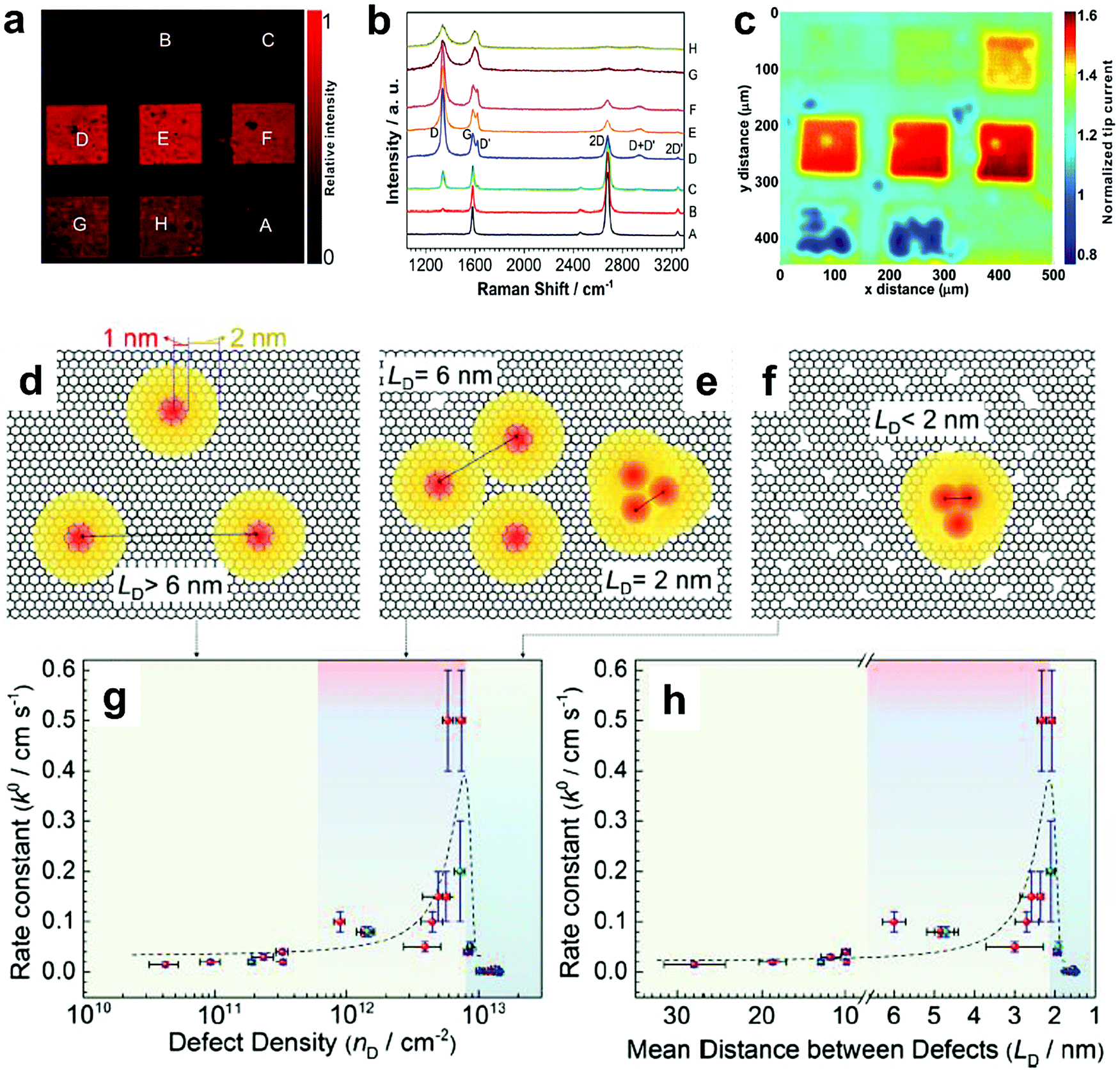 | ||
| Fig. 12 Correlations of carbon defect density and the heterogeneous electron-transfer (HET) rate of graphene (pattern A: pristine graphene, pattern B to H: defective graphene after Ar+ radiation). (a and b) Raman mapping of the D band of the defective graphene patterns and the corresponding Raman spectra. (c) Scanning electrochemical microscopy (SECM) images of the same defective graphene patterns. (d–f) The microscopic models in different defect density ranges (the red zone presents the structurally disordered area, and the yellow zone presents the electronically activated area): (d) low defect density with LD > 6 nm; (e) moderate defect density with 2 nm ≤ LD ≤ 6 nm; (f) high defect density with LD < 2 nm. (g) The standard HET rate constant k0 as a function of defect density nD (cm−2), and (h) the mean distance between defects LD (nm). Reproduced with permission.118 Copyright 2014, American Chemical Society. | ||
Based on above review of the correlations between the electronic structures and electrocatalysis in defective carbons, it can be concluded that two main factors (defect types and defect density) are crucial to the specific electrochemical activities (ORR, OER and HER) in carbon-based electrocatalysts.
4. Conclusive remarks and prospects
Carbon-based materials feature unique advantages for designated catalysis due to their various merits. However, to date, the electrochemical activities of these electrocatalysts have usually been attributed to different active dopants (e.g. N, B, P or S), whereas the contribution of intrinsic/induced carbon defects has often been neglected. Recently, studies on defects-promoted electrochemical reactions has been a hot topic, and is now gaining increasing research attention. In particular, a series of recently reported defective carbon-based materials showcase excellent electrochemical activities in ORR, OER and HER. More importantly, a defect catalysis mechanism originating from both defect types and defect density is introduced in this review, which may provide guidance to the proof-of-concept atomic designs of highly active electrocatalysts for diverse applications in energy conversion and storage.Although great advances have been made in the design of defective carbon-based materials as newly efficient and robust electrocatalysts by combining the currently available computational and experimental methods, there are still several critical challenges that are not addressed yet: (1) it is difficult to precisely control the defect types in carbons by current thermal treatments or direct radiation methods, leading to low selectivity to specific electrochemical reactions; (2) correlation analysis between the defect density and electrocatalytic activity is still lacking in the present development stage of defective carbon-based catalysts for ORR, OER or HER; (3) despite defective carbons exhibiting significant enhancement in ORR (e.g. D-AC comparable to Pt/C) and OER (e.g. DG comparable to Ir/C) in alkaline conditions, their electrochemical performance still need further improvement due to their inferiority to the Pt-based benchmark catalyst in more broad applications, such as ORR in acidic conditions.
In conclusion, the future directions of catalyst development for defect chemistry in electrocatalysis should be focused on the following aspects: (1) new synthetic strategies must be developed to experimentally precisely control the defect type for only enhancing one specific electrochemical reaction without side effects, which means it is difficult but important to identify the real active sites of defects (e.g. N-removal from specific types of N dopants); (2) quantitatively optimising the electrocatalytic activity by balancing the defect density to induce an increase in the density of states (DOS) and a decrease in the conductivity in defective carbons; (3) utilization of defect sites in defective carbons for efficiently and largely anchoring metallic dopants at the atomic level, which could open a new venue towards single-atom catalysis (a new research frontier in heterogeneous catalysis); and (4) cost-effective large-scale production of tailor-made defective carbon-based catalysts is necessary for industrial applications. Prospectively, there is no doubt that continued research and development in this exciting field should result in improved fuel economy and decreased harmful emissions.
Conflicts of interest
There are no conflicts to declare.Acknowledgements
We thank the financial support from Australian Research Council (ARC DP170103317 and DP170102267). Y. J. also thanks the ARC Discovery Early Career Researcher Award (ARC DE180101030).Notes and references
- R. Bashyam and P. Zelenay, Nature, 2006, 443, 63 CrossRef CAS PubMed.
- G. Wu, K. L. More, C. M. Johnston and P. Zelenay, Science, 2011, 332, 443 CrossRef CAS PubMed.
- N. Yamada, T. Yaguchi, H. Otsuka and M. Sudoh, J. Electrochem. Soc., 1999, 146, 2587 CrossRef CAS.
- L. M. Dai, Y. H. Xue, L. T. Qu, H. J. Choi and J. B. Baek, Chem. Rev., 2015, 115, 4823 CrossRef CAS PubMed.
- J. T. Zhang, Z. H. Zhao, Z. H. Xia and L. M. Dai, Nat. Nanotechnol., 2015, 10, 444 CrossRef CAS PubMed.
- Y. G. Li and H. J. Dai, Chem. Soc. Rev., 2014, 43, 5257 RSC.
- Y. Jiao, Y. Zheng, M. T. Jaroniec and S. Z. Qiao, Chem. Soc. Rev., 2015, 44, 2060 RSC.
- X. X. Zou and Y. Zhang, Chem. Soc. Rev., 2015, 44, 5148 RSC.
- Y. Y. Liang, Y. G. Li, H. L. Wang and H. J. Dai, J. Am. Chem. Soc., 2013, 135, 2013 CrossRef CAS PubMed.
- Y. Y. Liang, Y. G. Li, H. L. Wang, J. G. Zhou, J. Wang, T. Regier and H. J. Dai, Nat. Mater., 2011, 10, 780 CrossRef CAS PubMed.
- S. Cobo, J. Heidkamp, P. A. Jacques, J. Fize, V. Fourmond, L. Guetaz, B. Jousselme, V. Ivanova, H. Dau, S. Palacin, M. Fontecave and V. Artero, Nat. Mater., 2012, 11, 802 CrossRef CAS PubMed.
- H. Y. Jin, J. Wang, D. F. Su, Z. Z. Wei, Z. F. Pang and Y. Wang, J. Am. Chem. Soc., 2015, 137, 2688 CrossRef CAS PubMed.
- M. Gong, Y. G. Li, H. L. Wang, Y. Y. Liang, J. Z. Wu, J. G. Zhou, J. Wang, T. Regier, F. Wei and H. J. Dai, J. Am. Chem. Soc., 2013, 135, 8452 CrossRef CAS PubMed.
- E. J. Popczun, J. R. McKone, C. G. Read, A. J. Biacchi, A. M. Wiltrout, N. S. Lewis and R. E. Schaak, J. Am. Chem. Soc., 2013, 135, 9267 CrossRef CAS PubMed.
- R. D. L. Smith, M. S. Prevot, R. D. Fagan, S. Trudel and C. P. Berlinguette, J. Am. Chem. Soc., 2013, 135, 11580 CrossRef CAS PubMed.
- Y. F. Xu, M. R. Gao, Y. R. Zheng, J. Jiang and S. H. Yu, Angew. Chem., Int. Ed., 2013, 52, 8546 CrossRef CAS PubMed.
- M. Gong, W. Zhou, M. C. Tsai, J. G. Zhou, M. Y. Guan, M. C. Lin, B. Zhang, Y. F. Hu, D. Y. Wang, J. Yang, S. J. Pennycook, B. J. Hwang and H. J. Dai, Nat. Commun., 2014, 5, 6 Search PubMed.
- X. Huang, C. L. Tan, Z. Y. Yin and H. Zhang, Adv. Mater., 2014, 26, 2185 CrossRef CAS PubMed.
- R. Lv, J. A. Robinson, R. E. Schaak, D. Sun, Y. F. Sun, T. E. Mallouk and M. Terrones, Acc. Chem. Res., 2015, 48, 56 CrossRef CAS PubMed.
- C. C. L. McCrory, S. Jung, I. M. Ferrer, S. M. Chatman, J. C. Peters and T. F. Jaramillo, J. Am. Chem. Soc., 2015, 137, 4347 CrossRef CAS PubMed.
- Y. G. Li, H. L. Wang, L. M. Xie, Y. Y. Liang, G. S. Hong and H. J. Dai, J. Am. Chem. Soc., 2011, 133, 7296 CrossRef CAS PubMed.
- T. F. Jaramillo, K. P. Jorgensen, J. Bonde, J. H. Nielsen, S. Horch and I. Chorkendorff, Science, 2007, 317, 100 CrossRef CAS PubMed.
- J. H. Wang, W. Cui, Q. Liu, Z. C. Xing, A. M. Asiri and X. P. Sun, Adv. Mater., 2016, 28, 215 CrossRef CAS PubMed.
- J. Liang, R. F. Zhou, X. M. Chen, Y. H. Tang and S. Z. Qiao, Adv. Mater., 2014, 26, 6074 CrossRef CAS PubMed.
- P. W. Du and R. Eisenberg, Energy Environ. Sci., 2012, 5, 6012 CAS.
- S. Najmaei, Z. Liu, W. Zhou, X. L. Zou, G. Shi, S. D. Lei, B. I. Yakobson, J. C. Idrobo, P. M. Ajayan and J. Lou, Nat. Mater., 2013, 12, 754 CrossRef CAS PubMed.
- K. P. Gong, F. Du, Z. H. Xia, M. Durstock and L. M. Dai, Science, 2009, 323, 760 CrossRef CAS PubMed.
- Y. Zheng, Y. Jiao, J. Chen, J. Liu, J. Liang, A. Du, W. M. Zhang, Z. H. Zhu, S. C. Smith, M. Jaroniec, G. Q. Lu and S. Z. Qiao, J. Am. Chem. Soc., 2011, 133, 20116 CrossRef CAS PubMed.
- Y. Zhao, R. Nakamura, K. Kamiya, S. Nakanishi and K. Hashimoto, Nat. Commun., 2013, 4, 7 Search PubMed.
- Y. Zheng, Y. Jiao, L. H. Li, T. Xing, Y. Chen, M. Jaroniec and S. Z. Qiao, ACS Nano, 2014, 8, 5290 CrossRef CAS PubMed.
- C. G. Hu and L. M. Dai, Angew. Chem., Int. Ed., 2016, 55, 11736 CrossRef CAS PubMed.
- Y. X. Fang and X. C. Wang, Angew. Chem., Int. Ed., 2017, 56, 15506 CrossRef CAS PubMed.
- X. E. Liu and L. M. Dai, Nat. Rev. Mater., 2016, 1, 16064 CrossRef CAS.
- J. T. Zhang, L. T. Qu, G. Q. Shi, J. Y. Liu, J. F. Chen and L. M. Dai, Angew. Chem., Int. Ed., 2016, 55, 2230 CrossRef CAS PubMed.
- H. H. Ou, P. J. Yang, L. H. Lin, M. Anpo and X. C. Wang, Angew. Chem., Int. Ed., 2017, 56, 10905 CrossRef CAS PubMed.
- C. Yang, B. Wang, L. Z. Zhang, L. Yin and X. C. Wang, Angew. Chem., Int. Ed., 2017, 56, 6627 CrossRef CAS PubMed.
- H. H. Ou, L. H. Lin, Y. Zheng, P. J. Yang, Y. X. Fang and X. C. Wang, Adv. Mater., 2017, 29, 1700008 CrossRef PubMed.
- P. J. Yang, H. H. Ou, Y. X. Fang and X. C. Wang, Angew. Chem., Int. Ed., 2017, 56, 3992 CrossRef CAS PubMed.
- F. S. Guo, P. J. Yang, Z. M. Pan, X. N. Cao, Z. L. Xie and X. C. Wang, Angew. Chem., Int. Ed., 2017, 56, 8231 CrossRef CAS PubMed.
- Y. X. Fang and X. C. Wang, Angew. Chem., Int. Ed., 2017, 56, 15506 CrossRef CAS PubMed.
- M. Z. Rahman, J. Zhang, Y. Tang, K. Davey and S. Qiao, Mater. Chem. Front., 2017, 1, 562 RSC.
- A. Eftekhari and Z. Fan, Mater. Chem. Front., 2017, 1, 1001 RSC.
- K. Zhu, Y. Wang, J. Tang, S. Guo, Z. Gao, Y. Wei, G. Chen and Y. Gao, Mater. Chem. Front., 2017, 1, 958 RSC.
- K. Yuan, T. Hu, Y. Xu, R. Graf, L. Shi, M. Forster, T. Pichler, T. Riedl, Y. Chen and U. Scherf, Mater. Chem. Front., 2017, 1, 278 RSC.
- L. J. Yang, S. J. Jiang, Y. Zhao, L. Zhu, S. Chen, X. Z. Wang, Q. Wu, J. Ma, Y. W. Ma and Z. Hu, Angew. Chem., Int. Ed., 2011, 50, 7132 CrossRef CAS PubMed.
- J. P. Paraknowitsch and A. Thomas, Energy Environ. Sci., 2013, 6, 2839 CAS.
- Y. Zhao, L. J. Yang, S. Chen, X. Z. Wang, Y. W. Ma, Q. Wu, Y. F. Jiang, W. J. Qian and Z. Hu, J. Am. Chem. Soc., 2013, 135, 1201 CrossRef CAS PubMed.
- H. Y. Zhao, C. H. Sun, Z. Jin, D. W. Wang, X. C. Yan, Z. G. Chen, G. S. Zhu and X. D. Yao, J. Mater. Chem. A, 2015, 3, 11736 CAS.
- X. J. Zhao, X. Q. Zou, X. C. Yan, C. L. Brown, Z. G. Chen, G. S. Zhu and X. D. Yao, Inorg. Chem. Front., 2016, 3, 417 RSC.
- Y. Jia, L. Z. Zhang, A. J. Du, G. P. Gao, J. Chen, X. C. Yan, C. L. Brown and X. D. Yao, Adv. Mater., 2016, 28, 9532 CrossRef CAS PubMed.
- C. Tang, H. F. Wang, X. Chen, B. Q. Li, T. Z. Hou, B. S. Zhang, Q. Zhang, M. M. Titirici and F. Wei, Adv. Mater., 2016, 28, 6845 CrossRef CAS PubMed.
- X. C. Yan, Y. Jia, T. Odedairo, X. J. Zhao, Z. Jin, Z. H. Zhu and X. D. Yao, Chem. Commun., 2016, 52, 8156 RSC.
- Y. Jiang, L. Yang, T. Sun, J. Zhao, Z. Lyu, O. Zhuo, X. Wang, Q. Wu, J. Ma and Z. Hu, ACS Catal., 2015, 5, 6707 CrossRef CAS.
- L. Tao, Q. Wang, S. Dou, Z. Ma, J. Huo, S. Wang and L. Dai, Chem. Commun., 2016, 52, 2764 RSC.
- Y. Tian, Y. F. Ye, X. J. Wang, S. Peng, Z. Wei, X. Zhang and W. M. Liu, Appl. Catal., A, 2016, 529, 127 CrossRef.
- H. J. Yu, R. Shi, Y. X. Zhao, T. Bian, Y. F. Zhao, C. Zhou, G. I. N. Waterhouse, L. Z. Wu, C. H. Tung and T. R. Zhang, Adv. Mater., 2017, 29, 1605148 CrossRef PubMed.
- X. C. Yan, Y. Jia, J. Chen, Z. H. Zhu and X. D. Yao, Adv. Mater., 2016, 28, 8771 CrossRef CAS PubMed.
- Y. Jia, L. Z. Zhang, G. P. Gao, H. Chen, B. Wang, J. Z. Zhou, M. T. Soo, M. Hong, X. C. Yan, G. R. Qian, J. Zou, A. J. Du and X. D. Yao, Adv. Mater., 2017, 29, 1700017 CrossRef PubMed.
- C. Tang, B. Wang, H. F. Wang and Q. Zhang, Adv. Mater., 2017, 29, 1703185 CrossRef PubMed.
- L. Z. Zhang, Y. Jia, G. P. Gao, X. C. Yan, N. Chen, J. Chen, M. T. Soo, B. Wood, D. J. Yang, A. Du and X. D. Yao, Chem, 2018, 4, 285 CAS.
- L. Liu, X. Yang, N. Ma, H. Liu, Y. Xia, C. Chen, D. J. Yang and X. D. Yao, Small, 2016, 12, 1295 CrossRef CAS PubMed.
- H. B. Yang, J. W. Miao, S. F. Hung, J. Z. Chen, H. B. Tao, X. Z. Wang, L. P. Zhang, R. Chen, J. J. Gao, H. M. Chen, L. M. Dai and B. Liu, Sci. Adv., 2016, 2, 11 Search PubMed.
- D. H. Guo, R. Shibuya, C. Akiba, S. Saji, T. Kondo and J. Nakamura, Science, 2016, 351, 361 CrossRef CAS PubMed.
- S. Kundu, T. C. Nagaiah, W. Xia, Y. M. Wang, S. V. Dommele, J. H. Bitter, M. Santa, G. Grundmeier, M. Bron, W. Schuhmann and M. J. Muhler, J. Phys. Chem. C, 2009, 113, 14302 CAS.
- H. B. Li, W. J. Kang, L. Wang, Q. L. Yue, S. L. Xu, H. S. Wang and J. F. Liu, Carbon, 2013, 54, 249 CrossRef CAS.
- C. V. Rao, C. R. Cabrera and Y. J. Ishikawa, J. Phys. Chem. Lett., 2010, 1, 2622 CrossRef CAS.
- K. A. Kurak and A. B. Anderson, J. Phys. Chem. C, 2009, 113, 6730 CAS.
- J. Yan, H. Meng, F. Y. Xie, X. L. Yuan, W. D. Yu, W. R. Lin, W. P. Ouyang and D. S. Yuan, J. Power Sources, 2014, 245, 772 CrossRef CAS.
- M. Park, T. Lee and B. S. Kim, Nanoscale, 2013, 5, 12255 RSC.
- S. Yasuda, L. Yu, J. Kim and K. Murakoshi, Chem. Commun., 2013, 49, 9627 RSC.
- D. Guo, R. Shibuya, C. Akiba, S. Saji, T. Kondo and J. Nakamura, Science, 2016, 351, 6271 CrossRef PubMed.
- L. Qu, Y. Liu, J. B. Baek and L. M. Dai, ACS Nano, 2010, 4, 1321 CrossRef CAS PubMed.
- R. L. Liu, D. Q. Wu, X. L. Feng and K. Mullen, Angew. Chem., Int. Ed., 2010, 49, 2565 CrossRef CAS PubMed.
- H. Niwa, K. Horiba, Y. Harada, M. Oshima, T. Ikeda, K. Terakura, J. Ozaki and S. Miyata, J. Power Sources, 2009, 187, 93 CrossRef CAS.
- D. S. Geng, Y. Chen, Y. G. Chen, Y. L. Li, R. Y. Li, X. L. Sun, S. Y. Ye and S. Knights, Energy Environ. Sci., 2011, 4, 760 CAS.
- B. Zheng, J. Wang, F. B. Wang and X. H. Xia, Electrochem. Commun., 2013, 28, 24 CrossRef CAS.
- Z. Y. Lin, G. H. Waller, Y. Liu, M. L. Liu and C. P. Wong, Nano Energy, 2013, 2, 241 CrossRef CAS.
- Y. Lei, L. Wei, S. Zhai, Y. Wang, H. E. Karahan, X. Chen, Z. Zhou, C. Wang, X. Sui and Y. Chen, Mater. Chem. Front., 2018, 2, 102 RSC.
- W. Wei, H. W. Liang, K. Parvez, X. D. Zhuang, X. L. Feng and K. Mullen, Angew. Chem., Int. Ed., 2014, 53, 1570 CrossRef CAS PubMed.
- S. Chen, J. Y. Bi, Y. Zhao, L. J. Yang, C. Zhang, Y. W. Ma, Q. Wu, X. Z. Wang and Z. Hu, Adv. Mater., 2012, 24, 5593 CrossRef CAS PubMed.
- Z. H. Sheng, L. Shao, J. J. Chen, W. J. Bao, F. B. Wang and X. H. Xia, ACS Nano, 2011, 5, 4350 CrossRef CAS PubMed.
- I. Y. Jeon, D. S. Yu, S. Y. Bae, H. J. Choi, D. W. Chang, L. M. Dai and J. B. Baek, Chem. Mater., 2011, 23, 3987 CrossRef CAS.
- D. S. Geng, Y. Chen, Y. G. Chen, Y. L. Li, R. Y. Li, X. L. Sun, S. Y. Ye and S. Knights, Energy Environ. Sci., 2011, 4, 760 CAS.
- P. Chen, T. Y. Xiao, Y. H. Qian, S. S. Li and S. H. Yu, Adv. Mater., 2013, 25, 3192 CrossRef CAS PubMed.
- Z. J. Wang, R. R. Jia, J. F. Zheng, J. G. Zhao, L. Li, J. L. Song and Z. P. Zhu, ACS Nano, 2011, 5, 1677 CrossRef CAS PubMed.
- Y. Kim, J. Ihm, E. Yoon and G. D. Lee, Phys. Rev. B: Condens. Matter Mater. Phys., 2011, 84, 5 Search PubMed.
- M. M. Ugeda, I. Brihuega, F. Hiebel, P. Mallet, J. Y. Veuillen, J. M. Gomez-Rodriguez and F. Yndurain, Phys. Rev. B: Condens. Matter Mater. Phys., 2012, 85, 5 CrossRef.
- A. Aijaz, N. Fujiwara and Q. Xu, J. Am. Chem. Soc., 2014, 136, 6790 CrossRef CAS PubMed.
- W. Xia, A. Mahmood, R. Q. Zou and Q. Xu, Energy Environ. Sci., 2015, 8, 1837 CAS.
- L. Zhang, Q. Xu, J. Niu and Z. Xia, Phys. Chem. Chem. Phys., 2015, 17, 16733 RSC.
- J. Kotakoski, A. V. Krasheninnikov, U. Kaiser and J. C. Meyer, Phys. Rev. Lett., 2011, 106, 4 CrossRef PubMed.
- F. Banhart, J. Kotakoski and A. V. Krasheninnikov, ACS Nano, 2011, 5, 26 CrossRef CAS PubMed.
- Z. F. Hou, X. L. Wang, T. Ikeda, K. Terakura, M. Oshima and M. Kakimoto, Phys. Rev. B: Condens. Matter Mater. Phys., 2013, 87, 16 CrossRef.
- B. Zhang, Z. H. Wen, S. Q. Ci, S. Mao, J. H. Chen and Z. He, ACS Appl. Mater. Interfaces, 2014, 6, 7464 CAS.
- F. Y. Cheng, J. A. Shen, B. Peng, Y. D. Pan, Z. L. Tao and J. Chen, Nat. Chem., 2011, 3, 79 CrossRef CAS PubMed.
- Y. Y. Liang, H. L. Wang, J. G. Zhou, Y. G. Li, J. Wang, T. Regier and H. J. Dai, J. Am. Chem. Soc., 2012, 134, 3517 CrossRef CAS PubMed.
- C. Li, X. P. Han, F. Y. Cheng, Y. X. Hu, C. C. Chen and J. Chen, Nat. Commun., 2015, 6, 8 Search PubMed.
- Y. Zheng, Y. Jiao, Y. H. Zhu, L. H. Li, Y. Han, Y. Chen, A. J. Du, M. Jaroniec and S. Z. Qiao, Nat. Commun., 2014, 5, 8 Search PubMed.
- L. T. Qu, Y. Liu, J. B. Baek and L. M. Dai, ACS Nano, 2010, 4, 1321 CrossRef CAS PubMed.
- L. P. Zhang and Z. H. Xia, J. Phys. Chem. C, 2011, 115, 11170 CAS.
- L. F. Lai, J. R. Potts, D. Zhan, L. Wang, C. K. Poh, C. H. Tang, H. Gong, Z. X. Shen, L. Y. Jianyi and R. S. Ruoff, Energy Environ. Sci., 2012, 5, 7936 CAS.
- W. Ding, Z. D. Wei, S. G. Chen, X. Q. Qi, T. Yang, J. S. Hu, D. Wang, L. J. Wan, S. F. Alvi and L. Li, Angew. Chem., Int. Ed., 2013, 52, 11755 CrossRef CAS PubMed.
- H.-W. Liang, X. Zhuang, S. Bruller, X. Feng and K. Mullen, Nat. Commun., 2014, 5, 4973 CrossRef CAS PubMed.
- T. Xing, Y. Zheng, L. H. Li, B. C. C. Cowie, D. Gunzelmann, S. Z. Qiao, S. M. Huang and Y. Chen, ACS Nano, 2014, 8, 6856 CrossRef CAS PubMed.
- D. C. Wei, Y. Q. Liu, Y. Wang, H. L. Zhang, L. P. Huang and G. Yu, Nano Lett., 2009, 9, 1752 CrossRef CAS PubMed.
- J. H. Chen, W. G. Cullen, C. Jang, M. S. Fuhrer and E. D. Williams, Phys. Rev. Lett., 2009, 102, 4 Search PubMed.
- C. R. Dean, A. F. Young, I. Meric, C. Lee, L. Wang, S. Sorgenfrei, K. Watanabe, T. Taniguchi, P. Kim, K. L. Shepard and J. Hone, Nat. Nanotechnol., 2010, 5, 722 CrossRef CAS PubMed.
- Z. H. Ni, L. A. Ponomarenko, R. R. Nair, R. Yang, S. Anissimova, I. V. Grigorieva, F. Schedin, P. Blake, Z. X. Shen, E. H. Hill, K. S. Novoselov and A. K. Geim, Nano Lett., 2010, 10, 3868 CrossRef CAS PubMed.
- L. G. Cancado, A. Jorio and M. A. Pimenta, Phys. Rev. B: Condens. Matter Mater. Phys., 2007, 76, 7 CrossRef.
- M. A. Pimenta, G. Dresselhaus, M. S. Dresselhaus, L. G. Cancado, A. Jorio and R. Saito, Phys. Chem. Chem. Phys., 2007, 9, 1276 RSC.
- A. C. Ferrari and J. Robertson, Phys. Rev. B: Condens. Matter Mater. Phys., 2000, 61, 14095 CrossRef CAS.
- A. C. Ferrari, S. E. Rodil and J. Robertson, Phys. Rev. B: Condens. Matter Mater. Phys., 2003, 67, 20 CrossRef.
- M. S. Dresselhaus, G. Dresselhaus, R. Saito and A. Jorio, Phys. Rep., 2005, 409, 47 CrossRef.
- L. G. Cancado, A. Jorio, E. H. M. Ferreira, F. Stavale, C. A. Achete, R. B. Capaz, M. V. O. Moutinho, A. Lombardo, T. S. Kulmala and A. C. Ferrari, Nano Lett., 2011, 11, 3190 CrossRef CAS PubMed.
- A. C. Ferrari, Solid State Commun., 2007, 143, 47 CrossRef CAS.
- A. C. Ferrari and D. M. Basko, Nat. Nanotechnol., 2013, 8, 235 CrossRef CAS PubMed.
- M. M. Lucchese, F. Stavale, E. H. M. Ferreira, C. Vilani, M. V. O. Moutinho, R. B. Capaz, C. A. Achete and A. Jorio, Carbon, 2010, 48, 1592 CrossRef CAS.
- J. H. Zhong, J. Zhang, X. Jin, J. Y. Liu, Q. Y. Li, M. H. Li, W. W. Cai, D. Y. Wu, D. P. Zhan and B. Ren, J. Am. Chem. Soc., 2014, 136, 16609 CrossRef CAS PubMed.
| This journal is © the Partner Organisations 2018 |