Metal-free bifunctional carbon electrocatalysts derived from zeolitic imidazolate frameworks for efficient water splitting†
Yaojie
Lei
a,
Li
Wei
 *a,
Shengli
Zhai
ab,
Yanqing
Wang
 c,
H. Enis
Karahan
b,
Xuncai
Chen
a,
Zheng
Zhou
a,
Chaojun
Wang
a,
Xiao
Sui
a and
Yuan
Chen
 *a
*a
aThe University of Sydney, School of Chemical and Biomolecular Engineering, Sydney, New South Wales 2006, Australia. E-mail: l.wei@sydney.edu.au; yuan.chen@sydney.edu.au
bNanyang Technological University, School of Chemical and Biomedical Engineering, 637459, Singapore
cThe University of Tokyo, Faculty of Engineering, Yayoi, Bunkyo-ku, Tokyo 113-0032, Japan
First published on 2nd November 2017
Abstract
Metal-free carbon catalysts have attracted great interest because of their high electrical conductivity, tailorable porosity and surface area, affordability, and sustainability. In particular, their bifunctional activity for hydrogen and oxygen evolution reactions (HER and OER) is attractive for electrochemical splitting of water. However, pristine carbon materials have low activities for HER/OER. Here, a high-performance carbon electrocatalyst is demonstrated by first pyrolyzing a metal–organic framework (MOF), i.e., zeolitic imidazolate framework-8 (ZIF-8), followed by optimized cathodic polarization treatment (CPT). Pyrolyzing ZIF-8 produces a highly N-doped (8.4 at%) carbon material having a large specific surface area of 1017 m2 g−1 with micro and mesopores. CPT in 0.5 M H2SO4 for up to 8 hours modulates the composition of N- and O-containing surface functional groups of the pyrolyzed ZIF-8 without sacrificing its large surface area and pore size distribution. After the 6-hour CPT, this material shows an excellent HER activity in 0.5 M H2SO4 electrolyte with an overpotential of 155 mV, a Tafel slope of 54.7 mV dec−1, and an exchange current density of 0.063 mA cm−2. And the 4-hour CPT results in excellent OER activity in 0.1 M KOH electrolyte with an overpotential of 476 mV and a Tafel slope of 78.5 mV dec−1. In a demonstration, these two carbon electrocatalysts steadily run a two-electrode water electrolyzer at a current density of 10 mA cm−2 over 8 hours under a potential of 1.82 V with a Faradaic efficiency of 98.0–99.1% in 0.1 M KOH electrolyte. The superior activity of the designed carbon electrocatalysts can be attributed to the functional group composition modulation achieved by CPT. High-performance metal-free carbon electrocatalysts derived from MOFs show excellent potentials for energy and environmental applications.
Introduction
H2 production by total water splitting is a promising approach for tackling the growing green energy needs, which requires high-performance yet affordable electrocatalysts for the cathodic hydrogen evolution and anodic oxygen evolution reactions (HER and OER).1–4 Bifunctional electrocatalysts for both HER and OER in the same medium can play a significant role in the realization of practically relevant electrolyzers by simplifying the design and also lowering the operational cost.1–4 However, established electrocatalysts with outstanding performances are based on precious metals, such as Pt, Ir, and IrO2, the widespread applications of which are difficult to sustain due to their scarcity and high cost.1,5 Carbon, on the other hand, is amenable for the large-scale production of low-cost electrocatalysts as an abundant element. However, pristine carbonaceous materials lag behind in HER/OER activity.Due to their low catalytic activity, carbon materials (with pristine π-networks) are commonly used as either the substrates for active metal electrocatalysts or synergistic co-catalysts in designing high-performance electrocatalysts.6–10 Various carbon-based materials, such as carbon nanotubes, graphene materials, carbon nitride, and their composites10–15 and many organic precursor-derived carbons,16–18 have been explored as metal-free electrocatalysts for HER or OER. In these studies, good electrical conductivity (that enhances charge transfer), large surface area (that accommodates abundant catalytic sites), and a porous carbon framework (that facilitates mass transfer of ions and gases in electrolytes) provided the base for catalyst design. On the other hand, both theoretical and experimental studies have shown that the introduction of elemental dopants, such as boron (B), nitrogen (N), oxygen (O), phosphorus (P), or sulphur (S), into carbon frameworks increases the catalytic activity for HER and OER.12,14–16,18–27 Specifically, carboxylic groups assist HER by serving as proton relays,11,17 and pyridinic N or ketonic O in carbon frameworks directly act as electrocatalytically active sites for OER.12,16,28,29 Nevertheless, it is still a challenge to optimally introduce such functionalities into carbon frameworks with a simple and potentially scalable method.
Recently, to exploit their highly defined chemical compositions and narrow pore size distributions, various metal–organic frameworks (MOFs) have been utilized as precursor materials to synthesize water-splitting electrocatalysts. In MOF-derived electrocatalysts, carbon frameworks usually serve as only conductive substrates, and the main catalytic sites originate from the incorporated metal carbides,30 oxides,31,32 selenides,33,34 or phosphides.35–37 And, to our knowledge, no metal-free carbon electrocatalysts with bifunctionality for HER/OER have been derived from MOFs. To achieve this, the key challenge is to tailor the (hetero)atom doping type and level as well as the surface functional group composition of the carbon framework. Based on our and other group's previous research,17,38 we have a rather established method for controlling the chemical dopant type and doping level in carbon materials. Therefore, we decided to tailor the functional group composition of a simple MOF-derived carbon material.
Thermal annealing has been used to control the chemical composition of MOF-derived carbon materials.9,16,19,23,39–41 However, complex reactions taking place at high thermal annealing temperatures complicate the property control, and the prolonged thermal stress often causes the collapse of porosities resulting in poor structural quality. As a rather “softer” chemical method, electrochemical polarization offers a way to preserve the structural architecture of carbon materials. In fact, electrochemical polarization has been widely used to activate solid electrode materials by changing the surface microstructure and chemistry of electrodes.42 Cathodic polarization treatment (CPT) has already been successfully applied to manipulate surface functionalities of carbon materials.11,17,42,43 However, to our knowledge, no study has exploited CPT for the modulation of the surface functional group composition of MOF-derived carbon materials.
Herein, we demonstrate a new facile method to synthesize high-performance bifunctional metal-free carbon electrocatalysts starting from a simple MOF structure, i.e., zeolitic imidazolate framework-8 (ZIF-8). We first converted ZIF-8 into an N-doped and hierarchical porous carbon material by high-temperature pyrolysis and acid leaching. Then, CPT over different durations was applied to modulate the surface functional group composition of the carbon material. We have studied the morphological and physicochemical properties of ZIF-8-derived carbon materials using scanning electron microscopy (SEM), energy-dispersive X-ray spectroscopy (EDX), N2 physisorption, and X-ray photoelectron spectroscopy (XPS). Then their catalytic activity for HER and OER was compared with those of commercial electrocatalysts. Finally, using optimal carbon electrocatalysts, efficient water splitting was demonstrated in a two-electrode water electrolyzer in an alkaline electrolyte. Importantly, we have extensively discussed the correlation between the catalytic activity and surface functional composition of the carbon electrocatalysts. As a fine-tunable combinatorial method, the proposed strategy is promising for the development of practically relevant carbon electrocatalysts for water splitting applications and beyond.
Experimental
ZIF-8 was purchased from Sigma-Aldrich and pyrolyzed at 900 °C for 3 hours in a flowing Ar environment (100 sccm, 99.99%, Coregas). The resulting material was washed with 1 M HCl solution to leach out the residual Zn and thoroughly rinsed with deionized water. Afterwards, the resulting carbon material was dried in a vacuum oven overnight and denoted as “ZIF-8-C0”. “C0” indicates that no CPT was applied: 0 hour.For CPT, the ZIF-8-derived carbon material (ZIF-8-C0) was first dispersed in isopropanol (IPA) by bath sonication to produce homogeneous dispersions. Next, the carbon/IPA dispersion was dropped on a piece of carbon cloth (2 × 2 cm2 in size) (ELAT LT1400, NuVant) with a mass loading of ∼2.5 mg cm−2 (total 10 mg on each carbon cloth electrode). The CPT was carried out using a three-electrode configuration in a two-chamber electrochemical cell separated by a glass frit. H2SO4 (0.5 M) aqueous solution was used as the electrolyte. The carbon cloth loaded with ZIF-8-C0 was used as the working electrode in one cell chamber. A carbon rod (99.999%, Strem Chemicals) and a saturated calomel electrode (SCE) were used as the counter and reference electrodes, respectively in the other cell chamber. CPT was applied on the working electrode at −2 V vs. SCE for 2, 4, 6, and 8 hours. Afterwards, the treated materials were recovered from the carbon cloth by short bath sonication in IPA (10 mL) and filtration. According to the treatment duration, the resulting carbon materials were denoted as “ZIF-8-C2”, “ZIF-8-C4”, “ZIF-8-C6”, and “ZIF-8-C8”.
The physicochemical properties of the carbon materials were characterized by a comprehensive set of techniques. Morphological properties were examined using a field emission SEM (FE-SEM, Jeol, JSM-6700F). Elemental distributions were assessed by EDX using the same FE-SEM. Specific surface areas were measured using a surface area analyzer (QuantaChrome, Autosorb-6B) based on the N2 physisorption test, and calculated by the Brunauer–Emmett–Teller (BET) method. Pore size distributions were calculated from their N2 physisorption isotherms using the non-local density functional theory (NL-DFT) method. Raman spectra were recorded on a Raman microscope (Renishaw, inVia) in the backscattering configuration under a 514 nm (2.41 eV) laser. Surface chemical compositions were analyzed by XPS (PHI, VersaProbe III) equipped with an Al-Kα (1486.3 eV) radiation source.
A standard glassy carbon electrode (GCE) was used (3 mm diameter, 0.07 cm2, CHI Instrument). Carbon materials (ZIF-8-C0–C8) were first dispersed in a water–IPA mixture (1/9, v/v; with 0.05 wt% Nafion) by bath sonication to form electrocatalyst inks at a concentration of 1 mg mL−1. Next, 20 μL of the electrocatalyst ink was first drop cast on a GCE, resulting in a mass loading of 0.3 mg cm−2. For each carbon material, at least three electrodes were prepared and tested. Commercial 20 wt% Pt/C and IrO2/C catalysts (Sigma-Aldrich) were also loaded on GCEs at the same mass loading as reference electrodes for comparison.
The electrocatalytic activity tests were carried out on an electrochemical workstation (CHI, 660E) in the three-electrode configuration. A graphite rod (99.999%, Strem Chemicals) and a SCE were used as the counter and reference electrodes, respectively. The HER activity was assessed in H2 saturated H2SO4 (0.5 M), potassium phosphate buffer (PBS, 0.5 M, pH = 7) and KOH (0.1 M) electrolytes. The OER performance was evaluated in O2 saturated PBS (0.5 M, pH = 7) and KOH (0.1 M) electrolytes. Linear sweep voltammetry (LSV) curves were obtained at a scan rate of 5 mV s−1 with 95% iR-compensation. Tafel plots were collected at a scan rate of 0.2 mV s−1.
Results and discussion
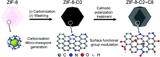
The production of carbon electrocatalysts starting from ZIF-8 is illustrated in Scheme 1. First, the ZIF-8 MOF particles were pyrolyzed at 900 °C to produce the N-doped and heteroporous carbon material (ZIF-8-C0). During pyrolysis, the imidazole rings expectedly serve as the main source of graphite-like carbon framework formation, and high N content of ZIF-8 (i.e., two N atoms per ligand, 2-methylimidazole) serves as chemical dopants. Then, Zn residues were removed by acid leaching using dilute HCl and water rinsing, resulting in the chemically doped and heteroporous carbon framework. Next, applying CPT at −2.0 V vs. SCE on ZIF-8-C0 loaded on carbon cloth over different periods of time (2–8 hours), we have modulated the type and relative abundance of different surface functional groups, resulting in a series of carbon materials (ZIF-8-C2–C8). To avoid the contamination from any Pt dissolution,44,45 the cathodic polarization was carried out in a two-cell electrolyzer separated with a 4 mm glass frit, and the carbon electrode (graphite rod) was used as the counter electrode.The physicochemical properties of the carbon materials were examined by several characterization techniques. Using SEM, we have compared the morphological properties of untreated, pyrolyzed, and CPT applied ZIF-8 particles (see Fig. 1 below and Fig. S1 in ESI†). ZIF-8 particles retain their polyhedron shape upon pyrolysis at 900 °C (compare untreated ZIF-8 particles in Fig. 1a and b with ZIF-8-C0 particles in Fig. 1c and d). And importantly, the morphology of both ZIF-8-C6 (Fig. 1e and f) and ZIF-8-C8 (Fig. S1 in ESI†) shows minor deviations from the shape of ZIF-8-C0 after being exposed to CPT, suggesting that our post-carbonization treatment routine made a minor impact on the overall structure of the ZIF-8-derived carbon materials.
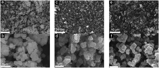 | ||
| Fig. 1 SEM images of (a and b) ZIF-8, (c and d) ZIF-8-C0, and (e and f) ZIF-8-C6 at different magnifications. | ||
As explained above, the overall shape characteristics of ZIF-8 particles can be preserved even after the longest CPT. Therefore, given that ZIF-8 is an intrinsically porous material, pyrolysis treatment inevitably creates volatile materials, and leaching of residual Zn should leave voids behind; one may expect the formation of different levels of porosities. Nevertheless, to determine the specific surface area and pore distribution of the carbon materials, we performed N2 physisorption analysis. Physisorption isotherms in Fig. 2a show mixed Type I and IV isotherms.46 The sharp uptakes in the low-pressure region (P/P0 < 0.15) indicate the existence of micropores, while the hysteresis in the medium pressure region (0.45 < P/P0 < 0.8) suggests the presence of mesopores. And importantly, pore size distributions calculated by the NL-DFT method show similar porosities for all samples, with micropores centered at 1.1 nm and mesopores at around 4.8 nm (Fig. 2b), which is in agreement with earlier reports on the carbonization of ZIF-8 for other purposes.47,48 With the extension of the CPT duration from 2 to 4, and 6 to 8 hours, the pore size distributions became slightly wider, which may be attributed to the minor physical changes in porosities and the variation of functional group composition. A previous study reported that surface functionalities can alter the pore edge structures of porous carbon materials, resulting in a wider pore size distribution.49 Consequently, as shown in Table 1, 2 hours of CPT caused only around 4.5% drop in the specific surface area (from 1017 to 961 m2 g−1). And, the extension of the treatment time from 2 to 8 hours showed a steadily decreasing trend from 961 to 908 m2 g−1 with ∼2% drop per 2 hours. Nevertheless, ZIF-8-C8 still retains a large specific surface area, i.e., ∼90% of the as-pyrolyzed material.
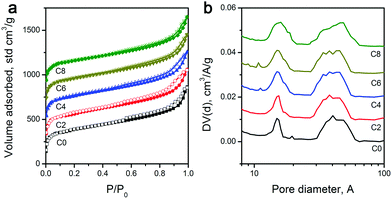 | ||
| Fig. 2 (a) N2 physisorption isotherms, and (b) pore size distributions of ZIF-8-derived carbon materials. | ||
| ZIF-8- | SSA, m2 g−1 | I D/IG | L a, nm | Elemental abundancea, at% | Normalized ECSA, m2 g−1 | ||
|---|---|---|---|---|---|---|---|
| C | N | O | |||||
| a As determined by both EDX and XPS (EDX/XPS). | |||||||
| C0 | 1017 | 1.04 | 4.20 | 90.8/90.7 | 8.4/8.3 | 0.8/1.0 | 785.7 |
| C2 | 961 | 1.09 | 3.98 | 90.5/90.3 | 7.5/7.3 | 2.0/2.4 | 764.3 |
| C4 | 947 | 1.16 | 3.75 | 86.4/85.9 | 6.5/6.4 | 5.1/7.3 | 740.5 |
| C6 | 923 | 1.25 | 3.48 | 83.5/82.7 | 5.4/5.1 | 11.1/12.2 | 706.0 |
| C8 | 908 | 1.31 | 3.32 | 79.5/78.9 | 1.9/1.3 | 18.6/19.8 | 557.7 |
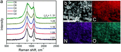
Raman spectra of the carbon materials are shown in Fig. 3a. A strong graphitic band (G-band) located at ∼1600 cm−1 can be found in the spectra, suggesting the formation of graphitic structures upon pyrolysis. The defect induced D-band peaks (at ∼1300 cm−1) got larger from ZIF-8-C0 to C8. The intensity ratio between the D-band and the G-band (ID/IG) is tabulated in Table 1, showing the continually increasing trend, which may be due to defect formation and chemical doping. The in-plane coherence length (La) provides the mean average crystallite size of sp2-hybridized carbon domains in the graphitic carbon framework.50La can be calculated from the ID/IG ratio using La = C(λ)/(ID/IG) with C(λ) at 4.35 nm for the 514 nm laser used, and the results are summarized in Table 1. The La value decreases from 4.20 nm of ZIF-8-C0 to 3.32 nm of ZIF-8-C8, indicating that the CPT changes the surface properties of the carbon materials.
The elemental composition of the carbon materials was assessed by EDX. The typical elemental mapping results obtained from ZIF-8-C6 are shown in Fig. 3b. C, N, and O uniformly distribute across the measured area. Inductively coupled plasma atomic emission spectroscopy was also applied to check whether metal contaminations exist or not. No Pt contaminants were found, and a trace amount of Zn at around 9.1 ppb was detected. Since Zn is not an active catalyst for OER/HER, we conclude that metal-free carbon materials were obtained.
The elemental abundance of C, N, and O are listed in Table 1. ZIF-8-C0 has the highest N abundance of 8.4 at% and the lowest O content of 0.8 at%. The CPT introduces O-containing functionalities onto the carbon surface, leading to the increase in the O abundance.51 The addition of these oxygenated functional groups can gradually improve the wettability of the carbon surface, which is beneficial for electrochemical reactions taking place at the solid–liquid interface. Fig. S2 in ESI,† shows that the contact angle of the carbon electrocatalysts decreases from 88.4° (ZIF-8-C0) to 67.6° (ZIF-8-C4), 58.8° (ZIF-8-C6), and 44.5° (ZIF-8-C8), confirming the increase in hydrophilicity introduced by CPT. Meanwhile, some N containing groups are removed, decreasing the N content. As a result, ZIF-8-C8 contains merely 1.9 at% of N but 18.6 at% of O. In summary, the characterization of ZIF-8-derived carbon materials indicates that the CPT can modulate the surface chemical composition of the carbon materials without significantly changing their morphology and pore structures.
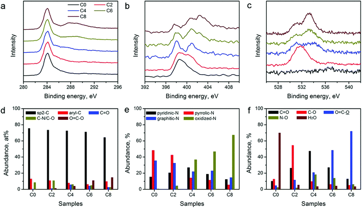
The catalytic activity of the carbon electrocatalysts for HER and OER strongly depends on the type and relative abundance of their surface functional groups. XPS was performed on the ZIF-8-derived carbon materials to further analyze their surface functional groups. XPS survey scans shown in Fig. S3 in the ESI† and the variations in the peak intensity of N and O agree with the elemental composition changes observed in EDX (Table 1). High-resolution XPS scans of C, N, and O in Fig. 4a–c show notable spectral changes, indicating that the CPT alters the surface functional group compositions significantly. Spectrum deconvolution was performed to determine the detailed changes in the C, N, and O-containing surface functionalities (see Fig. S4–S6 in ESI†). The relative abundance of C, N, and O in different functional groups is tabulated in Table S1 in the ESI.† The distributions of C, N, and O are also plotted in Fig. 4d–f for comparison. Fig. 4d shows that the sp2-hybridized C in the graphitic carbon framework is the major C species in all materials with a relative abundance of above 60%. The abundance of C in ketonic and carboxylic groups continually increases with the extension of the treatment duration, and reaches the maximum in ZIF-8-C8, indicating the formation of oxidized C functionalities during the CPT. N-Containing functionalities also show a systematic change. Fig. 4e indicates that oxidized N functionalities are virtually absent in ZIF-8-C0, while their relative abundance increases with the application of CPT. In contrast, the abundance of pyridinic, pyrrolic, and graphitic N functionalities decreases. Fig. 4f shows that the CPT also creates more oxygenated functional groups. Only 0.8 at% of O in ZIF-8-C0 can be assigned to chemisorbed water. After 2 hours of CPT, nearly 60% of O is in the form of hydroxyl or epoxy functional groups. And after 4 hours of CPT, these functionalities are oxidized to ketonic or carboxylic functional groups. Further treatment converts part of the ketonic groups into carboxylic groups. Overall, EDX and XPS results show that the CPT is an efficient method to modulate the type and density of the surface functional groups on the ZIF-8-derived carbon materials.
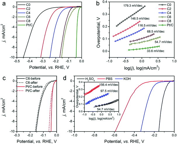
The HER electrocatalytic activity of the ZIF-8-derived carbon electrocatalysts was first evaluated in a H2-saturated acidic electrolyte (0.5 M H2SO4). The LSV curves are shown in Fig. 5a. The analysis results are summarized in Table 2 for comparison based on three performance parameters: (i) overpotential, (ii) Tafel slope, and (iii) exchange current density. The overpotential required to reach the geometric current density (j) of 10 mA cm−2 (η10) is the first performance parameter considered. The value of η10 gradually decreases from ∼451 mV for ZIF-8-C0 to 155 mV for ZIF-8-C6. However, it increases to 169 mV for ZIF-8-C8, suggesting that extended CPT is not desirable. The second parameter, the changed Tafel slopes, indicates that the HER reaction kinetics on the various carbon electrocatalysts is different. The Tafel slopes of ZIF-8-C0 and ZIF-8-C2 are 179.3 and 146.5 mV dec−1, respectively, suggesting that the initial H+ adsorption (the Volmer step) is the rate-limiting step on these two electrocatalysts. The Tafel slope of ZIF-8-C4 decreases to 116.5 mV dec−1, indicating that the rate-limiting step shifts to the electrochemical desorption (note that the Heyrovsky step has the Tafel slope of 40–120 mV dec−1). The Tafel slope of ZIF-8-C6 is the smallest at 54.7 mV dec−1. However, it increases to 68.5 mV dec−1 for ZIF-8-C8. ZIF-8-C6 shows the best HER kinetic performance among the five ZIF-8-derived carbon electrocatalysts. The Tafel slope of ZIF-8-C6 approaches that of the state-of-the-art commercial 20 wt% Pt/C (34.7 mV dec−1) catalyst. Similarly, the third performance parameter, the exchange current density (j0) of ZIF-8-C6 is the highest at 0.063 mA cm−2, which is more than two times larger than those of our previously reported N and P dually doped carbon electrocatalysts.17
| ZIF-8- | HER activity in 0.5 M H2SO4 | OER activity in 0.1 M KOH | |||
|---|---|---|---|---|---|
| η 10, mV | Tafel slope, mV dec−1 | j 0, mA cm−2 | η 10, mV | Tafel slope, mV dec−1 | |
| C0 | 451 | 179.3 | 0.010 | 798 | 192.1 |
| C2 | 316 | 146.5 | 0.016 | 620 | 167.2 |
| C4 | 245 | 116.5 | 0.027 | 476 | 78.5 |
| C6 | 155 | 54.7 | 0.063 | 528 | 91.9 |
| C8 | 169 | 68.5 | 0.049 | 570 | 139.4 |
Next, the electrocatalytic durability of the optimal ZIF-8-C6 was compared with that of the commercial Pt/C catalyst. First, the cycling test was conducted in 0.5 M H2SO4 from −0.2 to 0 V (vs. RHE) at a scan rate of 50 mV s−1 for 2000 cycles. The LSV curves obtained before and after the cycling test are shown in Fig. 5c. The η10 value of ZIF-8-C6 increases by merely 8 mV, which is much smaller than the 18 mV increment of Pt/C. Next, the chronoamperometric test was carried out in 0.5 M H2SO4 at 10 mA cm−2 for 10 hours (see Fig. S7 in ESI†). The overpotential required by ZIF-8-C6 increases by ∼4.4%. In comparison, it increases by ∼12.5% for the commercial Pt/C catalyst. These two tests indicate the excellent durability of ZIF-8-C6. Lastly, the HER electrocatalytic activity of ZIF-8-C6 in neutral or basic electrolytes was also tested, and the results are shown in Fig. 5d. The η10 value and Tafel slope increase marginally to 590 mV and 156.4 mV dec−1 in 0.5 M neutral PBS (pH = 7) solution and 336 mV and 97.5 mV dec−1 in 0.1 M KOH. These results show that it is feasible to apply ZIF-8-C6 for H2 production in water electrolyzers with neutral or basic electrolytes.
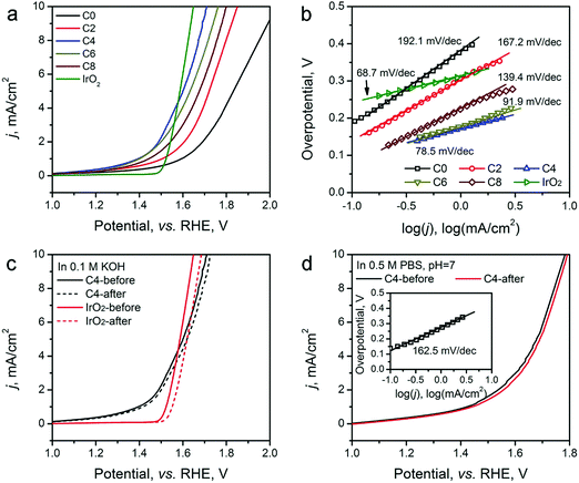
The OER activity of the ZIF-8-derived carbon electrocatalysts was evaluated in O2-saturated basic electrolyte (0.1 M KOH), and the results are shown in Fig. 6a and b, Table 2. Similar to their electrocatalytic activity for HER, Fig. 6a shows that their electrocatalytic activity for OER strongly depends on the CPT. ZIF-8-C0 has the largest η10 of 798 mV and Tafel slope of 192.1 mV dec−1. These values decrease with the extension of the CPT duration. ZIF-8-C4 has the smallest η10 of 476 mV and Tafel slope of 78.5 mV dec−1, exhibiting one of the best performances among recently reported carbon OER electrocatalysts, such as surface N-enriched CNTs (η10 = 510 mV),26 a N,O-dually doped carbon hydrogel (564 mV at 14.8 mA cm−2 and 141 mV dec−1),52 few-layer N-doped graphene (η10 > 1 V),53 and a C3N4–graphene hybrid (η10 = 539 mV).54 However, the electrocatalytic activity deteriorates when the CPT duration goes beyond 4 hours. Furthermore, to obtain a deeper understanding regarding the nature of observed high performances, we have performed electrochemical impedance spectroscopy (EIS) analysis on the ZIF-8-derived carbon electrocatalysts at an overpotential of 0.3 V in 0.1 M KOH electrolyte. The Nyquist plots were fitted with the Randel circuit to estimate the electrocatalysts’ polarization resistance (RP) (see Fig. S8 in ESI†). ZIF-8-C0 has the largest RP of 70.4 ohm. RP quickly decreases to the minimum of 17.78 ohms for ZIF-8-C4, but it increases with the extension of CPT duration. The lowest polarization resistance of ZIF-8-C4 is also a contributing factor to the observed high electrocatalytic activity.
The porous structure of the ZIF-8-derived carbon electrocatalysts can improve the mass transportation of ions in the electrolyte and gases generated.52,55 Such effectiveness has been demonstrated by measuring the OER performance of the optimal ZIF-8-C4 at different LSV scan rates from 5 to 100 mV s−1. As shown in Fig. S9 in the ESI,† the observed current density is almost identical, indicating highly efficient mass transportation.52
We further compared the durability of OER electrocatalytic activity of ZIF-8-C4 with that of the commercial IrO2 catalyst in 0.1 M KOH electrolyte by CV cycling and chronoamperometric tests. The results given in Fig. 5c show that after 2000 CV cycles from 1.2 to 1.8 V (vs. RHE), ZIF-8-C4 has an increment of 16 mV in its η10, which is much smaller than that of IrO2 at 52 mV. The chronoamperometric test (see Fig. S10 in ESI†) performed in 0.1 M KOH at 10 mA cm−2 for 10 hours yielded similar results. The overpotential required by ZIF-8-C4 increases by ∼6.8% after 10 hours, while the overpotential required by IrO2 increases by ∼15.1%. Lastly, Fig. 5d shows that ZIF-8-C4 also has a reasonably good electrocatalytic activity and cycling stability in the neutral 0.5 M PBS buffer (pH = 7), suggesting the possible application of ZIF-8-C4 for water splitting in neutral electrolytes.
The above catalytic performance evaluations show an obvious correlation between the HER/OER activity and the CPT duration. We explored the possible role of the surface area, pore size distribution, and surface functionality changes of carbon materials induced by the CPT. First, we examined the changes in surface area. The electrochemical active surface area (ECSA) of various ZIF-8-derived carbon electrocatalysts were determined by measuring their electrochemical double layer capacitance using the carbon cloth electrodes in 0.5 H2SO4 electrolyte, and the results are shown in Table 1 and Fig. S11 in the ESI.† The cathodic activation induced minor decreases in the ECSA of the ZIF-8-derived carbon electrocatalysts. Compared with the 785.7 m2 g−1 of ZIF-8-C0, ZIF-8-C4 and ZIF-8-C6 retained the large ECSA of 740.5 and 706.0 m2 g−1, respectively. Second, Fig. 2 shows that the pore size distributions of the carbon electrocatalysts are almost identical. Thus, we concluded that the surface area and pore size distribution are not the major contributing factors for the observed correlation. Next, we examined whether the correlation originates from the changes in N- and O-containing surface functional groups. Such functional groups have been found to cause variations in surface charge density of carbons and strongly influenced the electrochemical activity of carbon materials.56,57 As shown in Fig. 7a, the two HER performance parameters, namely the η10 and Tafel slope, are plotted against the abundance changes of several O and N functionalities calculated from XPS analysis (see Tables S1 and S2 in ESI†). Oxidized N and carboxylic O have been proposed as active sites in carbon electrocatalysts for HER.11,17Fig. 7a shows that the HER performance gets better with the increase of these two functional groups. ZIF-8-C6 having the high concentration of these active sites shows the highest catalytic activity. Extending the treatment duration to 8 hours could further increase the abundance of carboxylic O. However, the increased ID/IG ratio observed in its Raman spectrum suggests more defective sites and more severe structural damage in the graphitic carbon framework (Fig. 3a), which leads to reduced electrical conductivity (Fig. S8 in ESI†). In accordance, the HER performance of ZIF-8-C8 turned out to be poorer.
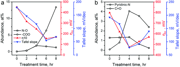 | ||
| Fig. 7 The corrections between the abundance of several major functional groups on ZIF-8-derived carbon electrocatalysts and their electrocatalytic performances for (a) HER (oxidized N and carboxylic O), and (b) OER (pyridinic N and ketonic O). The abundance of these functional groups (Table S2 in ESI†) is calculated using data in Table S1 in the ESI.† Electrocatalytic performances of η10 and Tafel slopes are extracted from Fig. 5 and 6. | ||
Recent experimental and theoretical studies have shown that p-type doping sites, such as pyridinic N and ketonic O, are responsible for the OER catalytic activity because these functional groups can withdraw electrons from adjacent C atoms to facilitate the adsorption of OH− and OOH− intermediates.12,16,29,58Fig. 7b shows that the OER performance has a strong connection with the abundances of pyridinic N and ketonic O. ZIF-8-C4 has the highest abundance of ketonic O (4.05 at%) and pyridinic N (1.35 at%) among the five ZIF-8-derived carbon electrocatalysts, which leads to the optimal OER electrocatalytic activity. Further extending the treatment duration results in the reduction of these active sites, and lowers the OER performance. Overall, Fig. 7 confirmed that the change in N- and O-containing surface functional groups induced by the CPT is the main reason for the observed improvement in HER/OER activity.
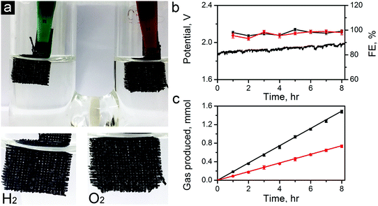
To further demonstrate the capability of the carbon electrocatalysts for efficient total water splitting, we have fabricated a two-electrode water electrolyzer using ZIF-8-C6 in the cathode (for HER), and ZIF-8-C4 in the anode (for OER) in 0.1 M KOH electrolyte (see the photo in Fig. 8a). For this demonstration, we have dropcast ZIF-8-C4 and ZIF-8-C6 on separate pieces of carbon clothes (1 × 1 cm2 each) with the areal mass loading of 0.5 mg cm−2. Fig. 8b shows that the electrolyzer can steadily work at a current density of 10 mA cm−2 over 8 hours at a potential around 1.82 V. Abundant H2 and O2 bubbles were observed on the electrode surfaces and they dissipated quickly in the electrolyte. H2 and O2 produced were quantified using a gas chromatograph (GC, Techcomp, GC7900). The results are shown in Fig. 8c together with the theoretical prediction. The Faradaic efficiency for HER and OER was calculated using the data in Fig. 8c and is plotted in Fig. 8b. The HER and OER have the Faradaic efficiency of 99.1 ± 1.4 and 98.0 ± 1.9, respectively. Moreover, the surface morphologies of ZiF-8-C4 and ZiF-8-C6 after the 8 hour electrolysis were examined by SEM. As shown in Fig. S12 in the ESI,† the particle shape and size have minor changes compared to the catalysts before the electrolysis test. The ECSA values of ZiF-8-C4 and ZiF-8-C6 after the 8 hour electrolysis were also measured. Results in Fig. S13 in the ESI† indicate that ECSA decreases by about 1.9 and 2.8% for ZiF-8-C6 and ZiF-8-C4, respectively. These results indicate that the metal-free bifunctional carbon electrocatalysts have good durability for full water splitting.
Conclusions
Pyrolyzing ZIF-8 at 900 °C in Ar results in an N-doped (8.4 at%) porous carbon material (ZIF-8-C0) having a specific surface area of 1017 m2 g−1 with micropores centered at 1.1 nm and mesopores at around 4.8 nm. CPT in 0.5 M H2SO4 can significantly change N- and O-containing surface functional groups while mostly retaining their large ECSA (764.2–706.01 m2 g−1) and pore size distribution. After 6 hours of CPT, the carbon material (ZIF-8-C6) contains 5.1 at% of N and 12.2 at% of O. Oxidized N and carboxylic O, which are related to the HER activity, reach 2.39 and 5.91 at%, respectively. ZIF-8-C6 shows excellent HER activity in 0.5 M H2SO4 electrolyte with an overpotential (η10) of 155 mV, a Tafel slope of 54.7 mV dec−1, and an exchange current density (j0) of 0.063 mA cm−2, as well better catalytic activity stability than that of the commercial Pt/C catalyst. It also has good HER activity in 0.1 M KOH with η10 of 336 mV and a Tafel slope of 97.5 mV dec−1. On the other hand, after 4 hours of the CPT, ZIF-8-C4 contains 6.4 at% of N and 7.3 at% of O. The high abundance of ketonic O (3.46 at%) and pyridinic N (1.73 at%) improves its OER catalytic activity, demonstrating excellent OER activity in 0.1 M KOH electrolyte with η10 of 476 mV and a Tafel slope of 78.5 mV dec−1, which is one of the best performances among recently reported carbon electrocatalysts for OER. ZIF-8-C4 also shows better catalytic activity stability than that of the commercial IrO2 catalyst. Integration of ZIF-8-C6 and ZIF-8-C4 as the cathode and anode in a two-electrode setup supported by 0.1 M KOH electrolyte enables efficient and steady water splitting at a current density of 10 mA cm−2 over 8 hours at a potential of 1.82 V with a Faradaic efficiency of 98.0–99.1%. This work shows that CPT can be applied to modulate the surface functional group composition of carbon electrocatalysts and improve the catalytic performance, demonstrating the great potential of the functional group modulation of MOF-derived carbons for the synthesis of metal-free carbon catalysts for energy and environmental applications.Conflicts of interest
There are no conflicts to declare.Acknowledgements
The authors would like to thank funding support from the Australian Research Council under the Future Fellowships scheme (FT160100107) and The University of Sydney.References
- M. G. Walter, E. L. Warren, J. R. McKone, S. W. Boettcher, Q. Mi, E. A. Santori and N. S. Lewis, Chem. Rev., 2010, 110, 6446–6473 CrossRef CAS PubMed.
- M. Götz, J. Lefebvre, F. Mörs, A. McDaniel Koch, F. Graf, S. Bajohr, R. Reimert and T. Kolb, Renewable Energy, 2016, 85, 1371–1390 CrossRef.
- H. Dau, C. Limberg, T. Reier, M. Risch, S. Roggan and P. Strasser, ChemCatChem, 2010, 2, 724–761 CrossRef CAS.
- I. C. Man, H. Y. Su, F. Calle-Vallejo, H. A. Hansen, J. I. Martinez, N. G. Inoglu, J. Kitchin, T. F. Jaramillo, J. K. Norskov and J. Rossmeisl, ChemCatChem, 2011, 3, 1159–1165 CrossRef CAS.
- C. C. L. McCrory, S. Jung, J. C. Peters and T. F. Jaramillo, J. Am. Chem. Soc., 2013, 135, 16977–16987 CrossRef CAS PubMed.
- S. H. Joo, S. J. Choi, I. Oh, J. Kwak, Z. Liu, O. Terasaki and R. Ryoo, Nature, 2001, 412, 169–172 CrossRef CAS PubMed.
- S. A. Grigoriev, P. Millet and V. N. Fateev, J. Power Sources, 2008, 177, 281–285 CrossRef CAS.
- Y. Liang, Y. Li, H. Wang and H. Dai, J. Am. Chem. Soc., 2013, 135, 2013–2036 CrossRef CAS PubMed.
- C. Hu and L. Dai, Angew. Chem., Int. Ed., 2016, 55, 11736–11758 CrossRef CAS PubMed.
- C. L. Su and K. P. Loh, Acc. Chem. Res., 2013, 46, 2275–2285 CrossRef CAS PubMed.
- W. Cui, Q. Liu, N. Cheng, A. M. Asiri and X. Sun, Chem. Commun., 2014, 50, 9340–9342 RSC.
- X. Lu, W.-L. Yim, B. H. R. Suryanto and C. Zhao, J. Am. Chem. Soc., 2015, 137, 2901–2907 CrossRef CAS PubMed.
- R. K. Das, Y. Wang, S. V. Vasilyeva, E. Donoghue, I. Pucher, G. Kamenov, H.-P. Cheng and A. G. Rinzler, ACS Nano, 2014, 8, 8447–8456 CrossRef CAS PubMed.
- T. Y. Ma, S. Dai, M. Jaroniec and S. Z. Qiao, Angew. Chem., Int. Ed., 2014, 53, 7281–7285 CrossRef CAS PubMed.
- J. Duan, S. Chen, M. Jaroniec and S. Z. Qiao, ACS Nano, 2015, 9, 931–940 CrossRef CAS PubMed.
- H. B. Yang, J. Miao, S. F. Hung, J. Chen, H. B. Tao, X. Wang, L. Zhang, R. Chen, J. Gao, H. M. Chen, L. Dai and B. Liu, Sci. Adv., 2016, 2, e1501122 Search PubMed.
- L. Wei, H. E. Karahan, K. Goh, W. Jiang, D. Yu, Ö. Birer, R. Jiang and Y. Chen, J. Mater. Chem. A, 2015, 3, 7210–7214 CAS.
- C. Hu and L. Dai, Adv. Mater., 2017, 29, 1604942 CrossRef PubMed.
- J. Zhang, Z. Zhao, Z. Xia and L. Dai, Nat. Nanotechnol., 2015, 10, 444–452 CrossRef CAS PubMed.
- W. Zhou, J. Jia, J. Lu, L. Yang, D. Hou, G. Li and S. Chen, Nano Energy, 2016, 28, 29–43 CrossRef CAS.
- G. Wu, A. Santandreu, W. Kellogg, S. Gupta, O. Ogoke, H. Zhang, H.-L. Wang and L. Dai, Nano Energy, 2016, 29, 83–110 CrossRef CAS.
- Y. Zheng, Y. Jiao, L. H. Li, T. Xing, Y. Chen, M. Jaroniec and S. Z. Qiao, ACS Nano, 2014, 8, 5290–5296 CrossRef CAS PubMed.
- A. Mulyadi, Z. Zhang, M. Dutzer, W. Liu and Y. Deng, Nano Energy, 2017, 32, 336–346 CrossRef CAS.
- Y. Zheng, Y. Jiao, Y. Zhu, L. H. Li, Y. Han, Y. Chen, A. Du, M. Jaroniec and S. Z. Qiao, Nat. Commun., 2014, 5, 3783 Search PubMed.
- T. Y. Ma, J. Ran, S. Dai, M. Jaroniec and S. Z. Qiao, Angew. Chem., Int. Ed., 2015, 54, 4646–4650 CrossRef CAS PubMed.
- G.-L. Tian, Q. Zhang, B. Zhang, Y.-G. Jin, J.-Q. Huang, D. S. Su and F. Wei, Adv. Funct. Mater., 2014, 24, 5956–5961 CrossRef CAS.
- R. Li, Z. Wei and X. Gou, ACS Catalysis, 2015, 5, 4133–4142 CrossRef CAS.
- N. Cheng, Q. Liu, J. Tian, Y. Xue, A. M. Asiri, H. Jiang, Y. He and X. Sun, Chem. Commun., 2015, 51, 1616–1619 RSC.
- L. Li, H. Yang, J. Miao, L. Zhang, H.-Y. Wang, Z. Zeng, W. Huang, X. Dong and B. Liu, ACS Energy Lett., 2017, 2, 294–300 CrossRef CAS.
- H. B. Wu, B. Y. Xia, L. Yu, X.-Y. Yu and X. W. D. Lou, Nat. Commun., 2015, 6, 6512 CrossRef CAS PubMed.
- W. Chaikittisilp, N. L. Torad, C. Li, M. Imura, N. Suzuki, S. Ishihara, K. Ariga and Y. Yamauchi, Chem. – Eur. J., 2014, 20, 4217–4221 CrossRef CAS PubMed.
- W. Chaikittisilp, N. L. Torad, C. Li, M. Imura, N. Suzuki, S. Ishihara, K. Ariga and Y. Yamauchi, Chem. – Eur. J., 2014, 20, 4217–4221 CrossRef CAS PubMed.
- C. Sun, Q. Dong, J. Yang, Z. Dai, J. Lin, P. Chen, W. Huang and X. Dong, Nano Res., 2016, 9, 2234–2243 CrossRef CAS.
- F. Ming, H. Liang, H. Shi, X. Xu, G. Mei and Z. Wang, J. Mater. Chem. A, 2016, 4, 15148–15155 CAS.
- B. You, N. Jiang, M. Sheng, S. Gul, J. Yano and Y. Sun, Chem. Mater., 2015, 27, 7636–7642 CrossRef CAS.
- L. Jiao, Y.-X. Zhou and H.-L. Jiang, Chem. Sci., 2016, 7, 1690–1695 RSC.
- X. Liu, J. Dong, B. You and Y. Sun, RSC Adv., 2016, 6, 73336–73342 RSC.
- L. Wei, H. E. Karahan, S. L. Zhai, Y. Yuan, Q. H. Qian, K. L. Goh, A. K. Ng and Y. Chen, J. Energy Chem., 2016, 25, 191–198 CrossRef.
- T. Asefa, Acc. Chem. Res., 2016, 49, 1873–1883 CrossRef CAS PubMed.
- Z. Lin, G. H. Waller, Y. Liu, M. Liu and C.-P. Wong, Nano Energy, 2013, 2, 241–248 CrossRef CAS.
- K. Qu, Y. Zheng, S. Dai and S. Z. Qiao, Nano Energy, 2016, 19, 373–381 CrossRef CAS.
- G. M. Swain, in Handbook of Electrochemistry, ed. C. G. Zoski, Elsevier, Amsterdam, 2007, p. 111 Search PubMed.
- S. Trasatti, Advances in Electrochemical Science and Engineering, Wiley-VCH Verlag GmbH, 2008, pp. 1–85 Search PubMed.
- R. Chen, C. Yang, W. Cai, H.-Y. Wang, J. Miao, L. Zhang, S. Chen and B. Liu, ACS Energy Lett., 2017, 2, 1070–1075 CrossRef.
- G. Dong, M. Fang, H. Wang, S. Yip, H.-Y. Cheung, F. Wang, C.-Y. Wong, S. T. Chu and J. C. Ho, J. Mater. Chem. A, 2015, 3, 13080–13086 CAS.
- S. Brunauer, L. S. Deming, W. E. Deming and E. Teller, J. Am. Chem. Soc., 1940, 62, 1723–1732 CrossRef CAS.
- R. R. Salunkhe, C. Young, J. Tang, T. Takei, Y. Ide, N. Kobayashi and Y. Yamauchi, Chem. Commun., 2016, 52, 4764–4767 RSC.
- W. Chaikittisilp, M. Hu, H. Wang, H.-S. Huang, T. Fujita, K. C. W. Wu, L.-C. Chen, Y. Yamauchi and K. Ariga, Chem. Commun., 2012, 48, 7259–7261 RSC.
- J. L. Figueiredo, M. F. R. Pereira, M. M. A. Freitas and J. J. M. Órfão, Carbon, 1999, 37, 1379–1389 CrossRef CAS.
- M. J. Matthews, M. A. Pimenta, G. Dresselhaus, M. S. Dresselhaus and M. Endo, Phys. Rev. B: Condens. Matter Mater. Phys., 1999, 59, R6585–R6588 CrossRef CAS.
- R. Berenguer, J. P. Marco-Lozar, C. Quijada, D. Cazorla-Amorós and E. Morallón, Carbon, 2009, 47, 1018–1027 CrossRef CAS.
- S. Chen, J. Duan, M. Jaroniec and S.-Z. Qiao, Adv. Mater., 2014, 26, 2925–2930 CrossRef CAS PubMed.
- Z. Lin, G. H. Waller, Y. Liu, M. Liu and C.-P. Wong, Carbon, 2013, 53, 130–136 CrossRef CAS.
- J. Tian, Q. Liu, A. M. Asiri, K. A. Alamry and X. Sun, ChemSusChem, 2014, 7, 2125–2130 CrossRef CAS PubMed.
- X. Li, Y. Fang, S. Zhao, J. Wu, F. Li, M. Tian, X. Long, J. Jin and J. Ma, J. Mater. Chem. A, 2016, 4, 13133–13141 CAS.
- J. Liang, Y. Jiao, M. Jaroniec and S. Z. Qiao, Angew. Chem., Int. Ed., 2012, 51, 11496–11500 CrossRef CAS PubMed.
- S. Gadipelli, T. Zhao, S. A. Shevlin and Z. Guo, Energy Environ. Sci., 2016, 9, 1661–1667 CAS.
- C. H. Choi, H.-K. Lim, M. W. Chung, J. C. Park, H. Shin, H. Kim and S. I. Woo, J. Am. Chem. Soc., 2014, 136, 9070–9077 CrossRef CAS PubMed.
Footnote |
| † Electronic supplementary information (ESI) available: SEM images, contact angle measurement, XPS spectra and analysis, chronoamperometric curves, EIS measurement and ECSA measurement. See DOI: 10.1039/c7qm00452d |
| This journal is © the Partner Organisations 2018 |

