
 Open Access Article
 This Open Access Article is licensed under a Creative Commons Attribution-Non Commercial 3.0 Unported Licence
High-pressure study of Li[Li1/3Ti5/3]O4 spinel†
Kazuhiko
Mukai
 *a and
Ikuya
Yamada
b
*a and
Ikuya
Yamada
b
aToyota Central Research & Development Laboratories, Inc., 41-1 Yokomichi, Nagakute, Aichi 480-1192, Japan. E-mail: e1089@mosk.tytlabs.co.jp
bDepartment of Materials Science, Graduate School of Engineering, Osaka Prefecture University, 1-2 Gakuen, Sakai, Osaka 599-8570, Japan
First published on 19th June 2018
Abstract
Crystal structures and electrochemical reactivities of high-pressure forms of the lithium titanium spinel Li[Li1/3Ti5/3]O4 (LTO) were investigated under a pressure of 12 GPa to elucidate its structural phase transition from spinel to post-spinel and to obtain a wide variety of electrode materials for lithium-ion batteries. LTO is recognized as a “zero-strain” lithium insertion material, because the change in the lattice parameter is negligibly small during charge and discharge reactions. As the heating temperature increased, the initially spinel-structured LTO decomposed into an amorphous phase at 400 °C and then changed into a mixture of columbite-type TiO2 (C-TiO2) and Li2O phases at temperatures above 600 °C. According to selected-area electron diffraction analyses, the amorphous phase at 400 °C was a mixture of two different phases, one of which was C-TiO2. Electrochemical investigations of the sample heated to 1000 °C exhibited stable charge and discharge curves with a rechargeable capacity of ∼40 mA h g−1, as was previously reported for C-TiO2. Details of the structural change from the spinel to columbite structure are also discussed in this report.
1 Introduction
The spinel oxide Li[Li1/3Ti5/3]O4 (LTO) maintains its cubic lattice parameter (ac) at an almost constant value (≈8.36 Å) during Li-insertion/extraction reactions.1,2 This is termed zero-strain characteristics, for which LTO has been regarded as an ideal electrode material for lithium-ion batteries (LIBs).1–5 In the crystal lattice of LTO, Li+ ions occupy both tetrahedral 8a and octahedral 16d sites, while Ti4+ ions occupy the 16d site, with the Fd![[3 with combining macron]](https://www.rsc.org/images/entities/char_0033_0304.gif) m space group (Fig. 1a). The relatively large O2− ions occupy the tetrahedral 32e site and form a cubic close-packed (ccp) array. Recently, ex situ Raman spectroscopic studies have revealed that the zero-strain characteristics are due to local structural changes in the LiO6 and TiO6 octahedra.6,7 Zero-strain or nearly zero-strain characteristics are also observed in other spinel compounds like Li1/2+x/2Fe5/2−3x/2TixO4 with 0.875 ≤ x < 5/3,8,9 LiRh2O4,10 and LiCoMnO4;11,12 however, in the case of LiCoMnO4, the rigid framework of the ccp lattice—not the local structural changes—contributes to the zero-strain reaction scheme.
m space group (Fig. 1a). The relatively large O2− ions occupy the tetrahedral 32e site and form a cubic close-packed (ccp) array. Recently, ex situ Raman spectroscopic studies have revealed that the zero-strain characteristics are due to local structural changes in the LiO6 and TiO6 octahedra.6,7 Zero-strain or nearly zero-strain characteristics are also observed in other spinel compounds like Li1/2+x/2Fe5/2−3x/2TixO4 with 0.875 ≤ x < 5/3,8,9 LiRh2O4,10 and LiCoMnO4;11,12 however, in the case of LiCoMnO4, the rigid framework of the ccp lattice—not the local structural changes—contributes to the zero-strain reaction scheme.
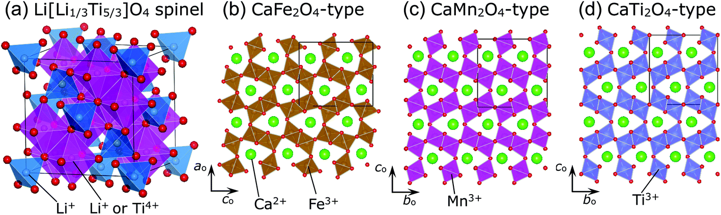 | ||
| Fig. 1 Schematic views of the (a) Li[Li1/3Ti5/3]O4 (LTO) spinel structure with the Fdm space group, (b) CaFe2O4-type structure with the Pnma space group, (c) CaMn2O4-type structure with the Pbcm space group, and (d) CaTi2O4-type structure with the Cmcm space group. The crystal symmetry of LTO is cubic, whereas the other three structures are orthorhombic. | ||
Spinel compounds such as MgAl2O4 usually undergo structural phase transitions at high pressures (HPs) above ∼4 GPa,13,14 and the compounds that have undergone phase transition are identified as post-spinel ones. There are three well-known post-spinel structures—CaFe2O4-,15–17 CaMn2O4-,16–18 and CaTi2O4-type16,19—as shown in Fig. 1b, c, and d, respectively. Each distorted MO6 (M = Fe, Mn, and Ti) octahedron in these structures is connected to three adjacent MO6 octahedra through edge-sharing or corner-sharing, forming the so-called double rutile chains. The three post-spinel structures are similar to each other; however, differences arise from the arrangements of the double-rutile chains and site symmetries of the M ions.15–19 Post-spinel compounds have recently received great attention as next-generation electrode materials for high-energy-density LIBs or other types of batteries,20–22 owing to their higher true densities compared to those of the parent spinel compounds. However, HP studies for such purposes have been limited, except for an investigation of LiMn2O4 that showed that it transforms into the CaFe2O4-type structure at 6 GPa and at temperatures above 1100 °C.23 This is probably because it is difficult to obtain a large amount of samples (>50 mg) under HPs above 6 GPa.
In this study, we performed HP studies of LTO under a pressure of 12 GPa and at temperatures up to 1000 °C and characterized the crystal structures from both macro- and microscopic viewpoints, by using X-ray diffraction (XRD), Raman spectroscopy, and selected area electron diffraction (SAED). Furthermore, we examined the electrochemical properties of the HP-treated LTO samples in nonaqueous lithium cells. This information could be crucial for gaining a deeper understanding of the electrochemical properties on structural factors, because the HP synthesis method provides novel polymorphs that cannot be obtained under ambient pressure.23–26 Moreover, HP studies on LTO would be useful to elucidate the structural phase transitions in the Earth's mantle. This is because MgSi2O4 with a γ-spinel structure decomposes into MgSiO3 (perovskite) and MgO under the transition layer of the Earth's mantle (>660 km).27 We have recently reported that one of the HP forms of TiO2 anatase (or rutile), columbite-type (α-PbO2-type) TiO2 (C-TiO2) with an orthorhombic structure, exhibits stable charge and discharge profiles with a rechargeable capacity (Qrecha) of ∼70 mA h g−1.28 Consequently, it was found that the HP-treated LTO samples at temperatures above 600 °C crystallize into a mixture of the C-TiO2 and Li2O phases, exhibiting similar charge and discharge profiles as those shown by C-TiO2.
2 Experimental
2.1 Synthesis
We first prepared the LTO sample under ambient pressure, as reported previously.6,7,9,29 LiOH·H2O and TiO2 anatase (Wako Pure Chemical Industries, Ltd) powders were mixed by using a mortar and pestle in a molar ratio of Li/Ti = 4.02/5.00, and then the resulting mixture was pressed into a pellet with an ∼23 mm diameter and ∼5 mm thickness. The pellet was heated at 750 °C in air for 12 h, followed by pre-heating at 400 °C in air for 12 h. We examined the crystal structure of the obtained sample using XRD (D8 ADVANCE, Bruker AXS, Inc.) equipped with copper Kα radiation, and confirmed that the LTO sample was in a single phase exhibiting the spinel structure with the Fdm space group (Fig. S1a†). The electrochemical reactivity of the LTO sample was investigated in a nonaqueous lithium cell. As shown in Fig. S1b,† the LTO sample showed a steady Qrecha with a value higher than 165 mA h g−1 in the voltage range between 1.0 and 3.0 V vs. Li+/Li. This LTO sample, LTO(raw), was packed into a platinum capsule with an ∼3 mm inner diameter and ∼5 mm height. The platinum capsule was installed into an octahedral (Mg,Co)O pressure medium with a side length of 14 mm (MINO CERAMICS Co., Ltd). The (Mg,Co)O octahedron was then placed in the corner made by eight WC anvils (FUJI DIE Co., Ltd) with eight truncations, and finally compressed to 12 GPa at room temperature. The HP syntheses were performed using Kawai-type high-pressure apparatus30 at Osaka Prefecture University. When the pressure reached 12 GPa, the sample was heated to 200, 400, 600, 750, or 1000 °C for 30 min. The time needed to approach each desired temperature was 15 min. After quenching to room temperature, the pressure was slowly released down to ambient pressure. Further details of the HP syntheses have been previously described.31,32 We denoted the HP samples heated to 200, 400, 600, 750, and 1000 °C as HP(200), HP(400), HP(600), HP(750), and HP(1000), respectively. In addition, HP(RT) represents the sample only pressurized at room temperature.
2.2 Characterization
The particle morphologies of LTO(raw), HP(200), HP(400), HP(600), HP(750), and HP(1000) samples were investigated by scanning electron microscopy (SEM; S-3600 N, Hitachi High-Technologies Co., Ltd). Their crystal structures were examined by XRD measurements and Raman spectroscopy (NRS-3300, Jasco Co. Ltd). Rietveld analyses were performed by using the software RIETAN-FP,33 and the schematics of the crystal structure were drawn by using the software VESTA.34 Raman spectroscopy was conducted using a 532 nm excitation wavelength supplied by a diode-pumped solid-state laser at room temperature. The intensity of the laser beam was 0.1 mW, and the acquisition time for each Raman spectrum was 10–90 s, as reported previously.6,7 For the LTO(raw), HP(400), and HP(1000) samples, transmission electron microscopy (TEM; JEM 2100F, JEOL Ltd) analyses including SAED pattern analyses and energy dispersive X-ray (EDX) spectroscopy studies were carried out to investigate the microscopic crystal structures and chemical compositions. For preparing the TEM specimens, we employed two different methods. For the LTO(raw) and HP(1000) samples, particles were dispersed in an acetone solution. Meanwhile, for the HP(200) sample, because particles form large secondary particles, as described later, the specimen was prepared by using a focused ion beam (FIB-SEM; NB-5000, Hitachi High-Technologies Co., Ltd). The sample was first attached to a SEM holder with carbon tape, and then cut into a rectangular solid with a Ga+-induced beam. The specimen was ∼10 μm in height, ∼6 μm in width, and ∼100 nm in depth (Fig. S2†).Because the HP(600), HP(750), and HP(1000) samples were slightly blue in color, magnetic susceptibility (χ) was measured to investigate the amount of localized moments in these samples. χ was obtained in the field-cooling (FC) mode using a superconducting interference magnetometer (MPMS, Quantum Design) under a magnetic field of 10 kOe. Details of the χ measurements have been provided in an earlier report.29
2.3 Electrochemical measurements
The electrochemical reactivities for the LTO(raw), HP(200), HP(400), HP(600), HP(750), and HP(1000) samples were investigated in nonaqueous lithium cells. We employed a dry process to prepare mixed electrodes, because the total amount of the HP-treated samples was limited to ∼50 mg. A mixed electrode consisting of 70 wt% active material, 25 wt% conducting carbon (acetylene black, HS-100, Denka Co., Ltd), and 5 wt% polytetrafluoroethylene (PTFE) was used as the working electrode (ϕ10), while a lithium metal pressed onto a stainless-steel plate (ϕ19) was used as the counter electrode. The addition of 25 wt% conducting carbon does not influence the capacity and operating voltage of the samples, as previously reported.28 The weights of the active materials were approximately 5 mg. The electrolyte used was 1 M LiPF6 dissolved in an ethylene carbonate (EC)/diethylene carbonate (DEC) (EC/DEC = 1/1 by volume) solution (Kishida Chemical Co., Ltd). The lithium cells were operated at a current of 0.05 mA and 25 °C in the voltage range between 0.02 and 3.0 V. This current corresponds to a current density of ∼0.07 mA cm−2 based on the surface area of the working electrode.3 Results and discussion
3.1 Particle morphology and color
Fig. 2 shows the SEM images of the (a) LTO(raw), (b) HP(RT), (c) HP(400), (d) HP(750), and (e) HP(1000) samples. For the LTO(raw) and HP(RT) samples, each primary particle within 1 μm aggregates together, forming a large secondary particle. The sizes of such secondary particles range between 5 and 10 μm. The particle morphology of HP(400) is quite different from that of LTO(raw) and HP(RT); i.e., its secondary particles indicate flat and squarish surfaces, as for compounds with a rock-salt structure.35 Moreover, the size of some secondary particles reaches ∼30 μm owing to the aggregation of several secondary particles. For HP(750), there are no large secondary particles, but there are many isolated primary particles with ∼500 nm instead. The particle sizes of HP(1000) are slightly larger than those of HP(750), as seen in the enlarged SEM image shown in Fig. 2f. The particle morphology of HP(1000) is similar to that of HP(750). | ||
| Fig. 2 SEM images at the 50 μm scale for (a) LTO(raw), (b) HP(RT), (c) HP(400), (d) HP(750), and (e) HP(1000). Enlarged SEM image of (e) at the 10 μm scale is shown in (f). | ||
Surprisingly, the color of particles changed with the HP treatment. As shown in Fig. 3a and b, LTO(raw) particles are white in color, whereas HP(1000) particles are light blue or navy blue in color. This indicates the formation of Ti3+ ions with the d1 configuration in the HP(1000) sample. Indeed, the χ value of the HP(1000) sample is larger than that of the LTO(raw) sample, particularly at temperatures below ∼60 K, due to the localized moments of the Ti3+ ions (Fig. 3c). The magnetic transitions at around 63 K (= Tm1) and 21 K (= Tm2) originate from either slight compositional deviation from stoichiometry or dislocations such as Magnéli phases in the pristine LTO sample.29 The temperature against the χ curve for HP(1000) was fitted by
 | (1) |
| Cm = Nμ2eff/3kB, | (2) |
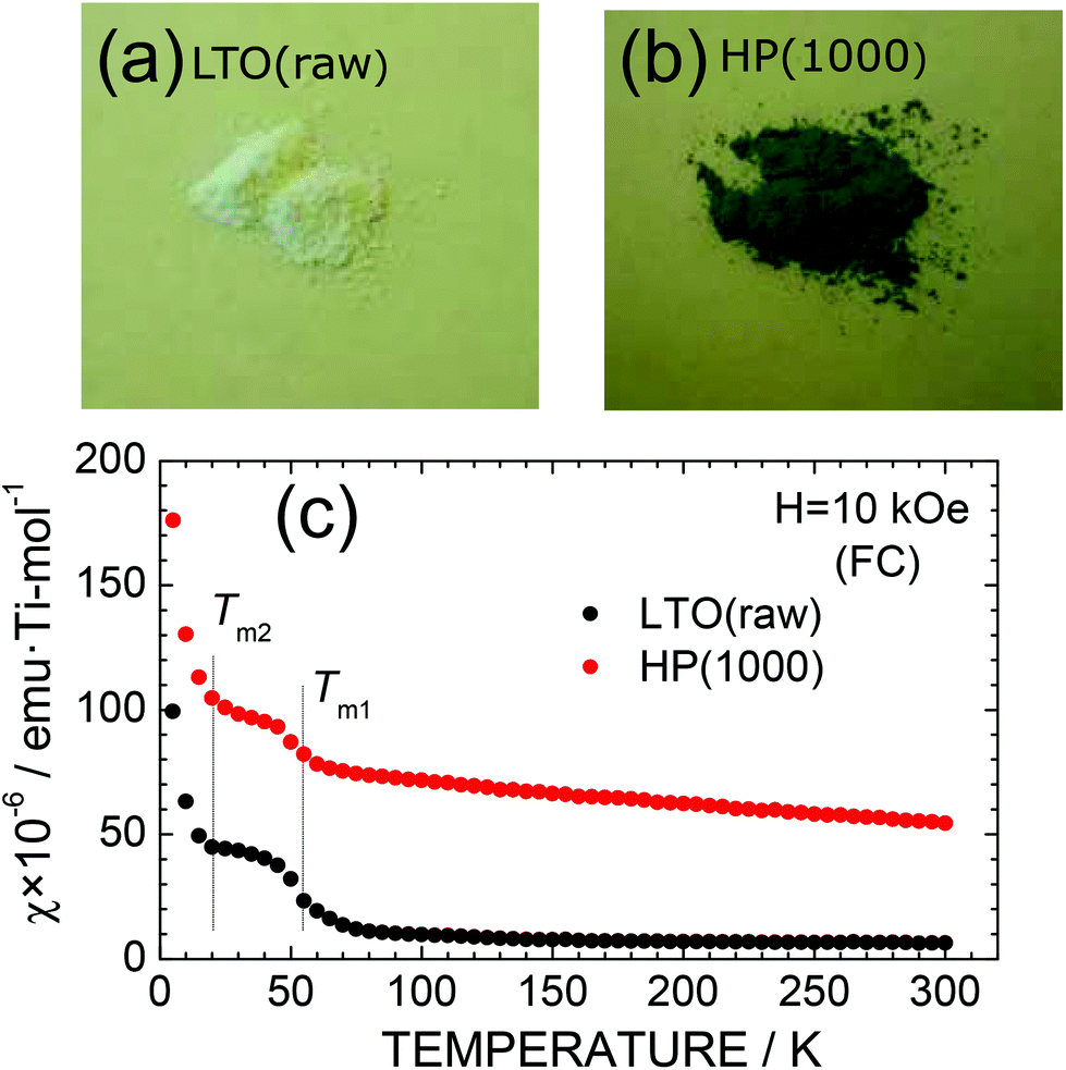 | ||
| Fig. 3 Particle color of the (a) LTO(raw) and (b) HP(1000) samples. (c) Temperature dependence of the magnetic susceptibility (χ) of the LTO(raw) and HP(1000) samples. χ was measured in the field-cooling (FC) mode with H = 10 kOe. | ||
3.2 Crystal structure
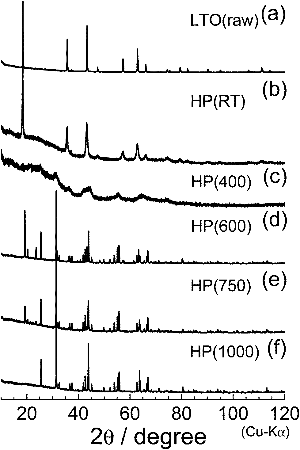
Fig. 4 shows the XRD patterns of the (a) LTO(raw), (b) HP(RT), (c) HP(400), (d) HP(600), (e) HP(750), and (f) HP(1000) samples. As described in Introduction, LTO(raw) has a spinel structure with the Fdm space group, in which Li+ ions occupy both tetrahedral 8a and octahedral 16d sites, and Ti4+ ions sit at the octahedral 16d site. The ac value determined by Rietveld analysis was 8.356(1) Å, consistent with previously quoted ac values.1–3,6,7,9,29 When HP was applied to the LTO(raw) sample (Fig. 4b), the ac value decreases slightly to 8.349(1) Å, accompanied by broadening of each diffraction line. When the heating temperature was increased to 400 °C (Fig. 4c), the original diffraction lines almost disappear, indicating that the sample is in an amorphous phase. For the HP(600) sample, new diffraction lines are observed at around 2θ = 19.14° (d = 4.63 Å) and 31.18° (d = 2.87 Å). The XRD pattern of the HP(750) sample is similar to that obtained for the HP(600) sample, but the XRD pattern of the HP(1000) sample lacks the diffraction line at around 2θ = 19.14°.
 | ||
| Fig. 4 XRD patterns of the (a) LTO(raw), (b) HP(RT), (c) HP(400), (d) HP(600), (e) HP(750), and (f) HP(1000) samples. | ||
Regarding lithium titanium oxides consisting of Ti4+ ions, little is known about their HP forms: only three structures under ambient pressure have been reported, —namely, Li2TiO3 with a monoclinic structure (C2/c),36 Li4TiO4 with an orthorhombic structure (Cmcm),37 and Li2Ti3O7 with an orthorhombic structure (Pbnm).38 The XRD pattern of HP(1000) could not be assigned to any of the three structures; however, a preliminary Le Bail analysis39 indicated that the major phase of HP(1000) is another orthorhombic structure. We then carried out Rietveld analysis with various orthorhombic phases, and found that the major phase of HP(1000) is in an orthorhombic structure with the Pbcn space group, where the lattice parameters are ao = 4.532(1) Å, bo = 5.501(1) Å, and co = 4.902(1) Å. These structural parameters were similar to those of C-TiO2 with the Pbcn space group,28,40 which is one of the HP forms of anatase TiO2 (I41/amd) and rutile TiO2 (P42/mnm).
Fig. 5a shows the final result of the Rietveld refinement of HP(1000). If we take into account only the C-TiO2 phase, differences between the observed and calculated patterns were seen particularly at 2θ = 43.84°, 63.87°, 80.75°, and 113.14° (Fig. S3†). In addition, reliability indices of the R-weighted pattern (Rwp) and scaling factor (S) were relatively low (Rwp = 15.9% and S = 3.31), indicating that another phase probably consisting of Li and O atoms is present in the HP(1000) sample. We then performed Le Bail analysis again, and found two possible structural models: two cubic structures with the Fmm (ac ≈ 5.89 Å) and Imm (ac ≈ 2.94 Å) space groups. Because the latter structural model provided better reliability indices, it is most likely that the HP(1000) sample is a mixture of the C-TiO2 phase with the Pbcn space group and the Li2O phase with the Imm space group. Structural parameters determined by the Rietveld refinement are listed in Table 1. Further Rietveld analyses using the XRD pattern obtained at a synchrotron radiation facility and the neutron diffraction pattern could clarify more precise occupancies of Li and O atoms in the C-TiO2 and Li2O phases.
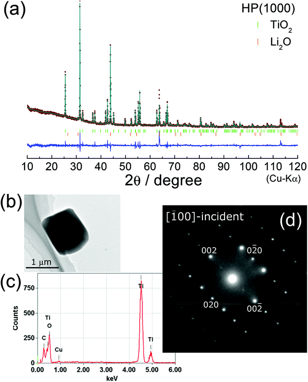 | ||
Fig. 5 (a) Rietveld refinement result for the HP(1000) sample. The XRD pattern is assigned to a mixture of columbite-type TiO2 (C-TiO2) and Li2O phases. The C-TiO2 phase crystallizes into an orthorhombic structure with the Pbcn space group with lattice parameters of ao = 4.532(1) Å, bo = 5.501(1) Å, and co = 4.902(1) Å. (b) TEM image and (c) the EDX spectrum for the HP(1000) sample. The SAED pattern from the [![[1 with combining macron]](https://www.rsc.org/images/entities/char_0031_0304.gif) 00]-incident is also shown in (d). The SAED pattern is well explained by the structural model determined by Rietveld refinement. 00]-incident is also shown in (d). The SAED pattern is well explained by the structural model determined by Rietveld refinement. | ||
| Space group | Atom | Wyckoff position | g | x | y | z | B iso (Å2) |
|---|---|---|---|---|---|---|---|
| Reliability indices: Rwp = 8.18% and S = 1.69. | |||||||
| Pbcn | Ti | 4c | 1 | 0 | 0.329(1) | 0.25 | 0.6(1) |
| O1 | 8d | 0.99(1) | 0.261(1) | 0.120(1) | 0.084(1) | 0.4(1) | |
| Lattice parameters: ao = 4.532(1) Å, bo = 5.501(1) Å, and co = 4.902(1) Å | |||||||
|
Imm |
Li | 12d | 0.73(1) | 0.25 | 0 | 0.5 | 0.7(1) |
| O | 6b | 0.73(1) | 0 | 0.5 | 0.5 | 0.4(1) | |
| Lattice parameter: ac = 2.923(1) Å | |||||||
We also investigated the microscopic crystal structure by EDX/SAED analyses for LTO(raw), HP(400), and HP(1000) samples. The SAED pattern for LTO(raw) was assigned to a spinel structure with the Fdm space group (Fig. S4†). As shown in Fig. 5b and c, the HP(1000) particle with a size of ∼1 μm consists of Ti and O atoms. Furthermore, the SAED pattern shown in Fig. 5d can be explained by an orthorhombic structure with the Pbcn space group; i.e., the SAED pattern and the nearest diffraction spots are attributed to the [00]-incident and the 020 (0![[2 with combining macron]](https://www.rsc.org/images/entities/char_0032_0304.gif) 0) spots, respectively. Hence, the EDX/SAED analyses were consistent with the Rietveld refinement results.
0) spots, respectively. Hence, the EDX/SAED analyses were consistent with the Rietveld refinement results.
As shown in Fig. 6a, two distinct regions, denoted as Region (I) and Region (II), are observed in the TEM specimen for HP(400). There are several straight lines in Region (I), indicating the presence of stacking faults or two-dimensional defects (Fig. 6b). According to the elemental mapping given by the EDX analyses, the O atoms are homogeneously distributed in both Regions (I) and (II), whereas the Ti atoms are unevenly distributed in the specimen: Region (II) contained slightly greater amounts of Ti atoms than Region (I) (Fig. 6c and d). We could not assign the SAED pattern for Region (I) using any structural model to the spinel (Fdm), anatase (I41/amd), rutile (P42/mnm), or C-TiO2 (Pbcn) phase. In contrast, the SAED pattern for Region (II) could be attributed to an orthorhombic structure with the Pbcn space group (C-TiO2 phase). Thus, although the XRD pattern for HP(400) indicated amorphous character, the SAED pattern clarified the presence of multiple phases in the sample. In other words, the structural transformation from spinel (Fdm) to C-TiO2 (Pbcn) proceeds not in a direct step, but in multiple steps, involving at least two different phases.
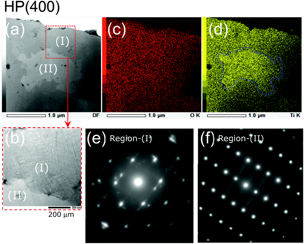 | ||
| Fig. 6 (a) TEM image of the HP(400) sample and (b) enlarged TEM image of the area surrounded by the broken line in (a). Two distinct regions are noted in the TEM specimen, denoted as Region (I) and Region (II). Elementary mapping of the HP(400) sample for (c) O and (d) Ti atoms. SAED patterns for (e) Region (I) and (f) Region (II). | ||
Raman spectroscopy provides structural information at the atomic scale, leading to an in-depth understanding of structural phase transitions of matter and change in the crystal structure of LIB materials. Indeed, we recently demonstrated that the zero-strain reaction scheme of LTO arises from structural changes in the LiO6 and TiO6 octahedra.6,7Fig. 7 shows the Raman spectra for the LTO(raw), HP(RT), HP(400), HP(750), and HP(1000) samples. For the LTO(raw) sample, three major Raman bands are observed at 671, 428, and 234 cm−1, while four minor Raman bands are observed at 762, 522, 341, and 147 cm−1. According to factor group analyses based on the Fdm space group,40 five Raman modes of A1g + Eg + 3F2g are predicted for the LTO(raw) sample. The three major Raman bands at 671, 428, and 234 cm−1 were assigned as the A1g mode for a symmetric vibration between Ti and O atoms, the Eg mode for an asymmetric vibration between Li and O atoms, and the F2g mode for a bending vibration between O–Ti–O atoms, respectively.6,7 The two minor Raman bands at 522 and 147 cm−1 come from the TiO2 anatase, which was used as a starting material. As seen in Fig. 7b, the Raman spectrum for HP(RT) is similar to that obtained for LTO(raw). This is consistent with the results of the XRD measurements that the HP(RT) sample is in the spinel phase with the Fdm space group (Fig. 4b).
 | ||
| Fig. 7 Raman spectra of the (a) LTO(raw), (b) HP(RT), (c) HP(400), (d) HP(750), and (e) HP(1000) samples. | ||
Before addressing the results for HP(400) and HP(750), we wish to discuss the Raman spectrum for HP(1000). XRD measurements indicated that the HP(1000) sample is a mixture of the C-TiO2 phase with the Pbcn space group and the Li2O phase with the Fmm space group. Based on factor group analyses,41 eighteen nondegenerate Raman bands of 4A1g + 5B1g + 4B2g + 5B3g are predicted for the Pbcn space group, while three Raman bands of 3F2g are predicted for the Fmm space group. As seen in Fig. 7e, there are at least twelve Raman bands; for instance, two strong Raman bands are observed at 429 and 174 cm−1, and five moderate Raman bands are observed at 443, 355, 315, 289, and 150 cm−1. According to previous experimental28,42 and theoretical43 Raman analyses of C-TiO2, all the Raman bands for HP(1000) could be explained by only the C-TiO2 phase. The two Raman bands at 429 and 174 cm−1 were assigned to the A1g mode and the three moderate Raman bands at 443, 315, and 289 cm−1 were assigned to the B1g mode.
The Raman spectrum for HP(750) is similar to that of HP(1000), and there is no trace of the Li2O1−δ phase with the Fmm space group in its Raman spectrum (Fig. 7d). In contrast, the Raman spectrum for HP(400) is different from that of LTO(raw) or HP(1000). Only three broad Raman bands are observed at 421, 317, and 166 cm−1 in the sample. This indicates the presence of an intermediate crystal structure when the spinel structure changed into the C-TiO2 structure. The disappearance of the original Raman bands and evolution of the new Raman bands are different from the recent results reported for an in situ HP Raman spectroscopy study of LTO,44i.e., no phase transitions were observed at room temperature except for the broadening of the original Raman bands.44
3.3 Electrochemical properties
Fig. 8 shows the charge and discharge curves for the nonaqueous lithium cells for the LTO(raw), HP(RT), HP(400), HP(750), and HP(1000) samples. Rescaled charge and discharge curves only for the HP(400), HP(750), and HP(1000) samples are shown in Fig. S5.† The initial discharge and charge curves were excluded from the figure to eliminate the contributions of the decomposition reaction of the PTFE binder. Moreover, we set the discharge cut-off voltage (Vcut) as 0.02 V to examine the entire range of the electrochemical reactivity of the HP samples, although the Vcut for LTO is usually set at 1.0 V.2,3,6,7 The cell voltage for LTO rapidly drops at ∼1.6 V at the beginning of the discharge reaction, and then maintains an almost constant voltage of around 1.5 V up to the discharge capacity (Qdis) of ∼130 mA h g−1, and finally decreases almost linearly down to 0.02 V. Since the C rate of the present study was extremely low (∼C/20), the flat operating voltage at ∼1.5 V suggests a two-phase reaction scheme, not a quasi-solid solution reaction scheme.5 The Qdis and charge capacity (Qcha) at the second cycle are 235.5 and 217.2 mA h g−1, respectively; this Qdis value is comparable with previously reported values for LTO (= 225 mA h g−1), where the Vcut was set at ∼0 V.45,46 If we assume that Li+ ions are inserted only into vacant octahedral 16c sites, the rechargeable capacity (Qrecha) can be calculated to be 175.1 mA h g−1. A value higher than 175 mA h g−1 for LTO(raw) indicates the additional Li occupation at the tetravalent 8a site, as probed by neutron diffraction measurements on a chemically Li-inserted LTO sample.45 | ||
| Fig. 8 Charge and discharge curves of the nonaqueous lithium cells of the (a) LTO(raw), (b) HP(RT), (c) HP(400), (d) HP(750), and (e) HP(1000) samples. The cells were operated at a current of 0.05 mA (≈0.07 mA cm−2) and 25 °C in the voltage range between 0.02 and 3.0 V. | ||
The charge and discharge curves for HP(RT) seem to be different from those for LTO(raw), regarding its Qrecha and voltage profile below ∼0.5 V. The Qdis and Qcha values in the second cycle were 198.7 and 175.5 mA h g−1, respectively (see Fig. 8b), where the Qrecha value around 1.5 V is limited to ∼70 mA h g−1. Furthermore, as shown in Fig. S6,† the derivative of Qdis with respect to the cell voltage, the dQdis/dV curve, indicates another cathodic reaction peak at ∼0.45 V. Since the line broadening was observed in the XRD pattern of HP(RT), the differences between HP(RT) and LTO(raw) are probably caused by the distortions and/or defects around the 16c site.
For the HP(400), HP(750), and HP(1000) samples, the redox reaction at around 1.5 V disappeared and the discharge (or charge) voltage gradually decreases (or increases) as the reaction proceeded. The Qdis and Qcha values in the second cycle are ∼60 and 40 mA h g−1, respectively. These electrochemical properties are similar to those reported for C-TiO2,28 although the Qdis and Qcha values of C-TiO2 were reported to be ∼100 and 70 mA h g−1, respectively. The decrease in Qdis and Qcha values can probably be attributed to the presence of Li2O, which is electrochemically inactive. However, the reversible charge and discharge reactions of the HP(400), HP(750), and HP(1000) samples indicate that the Li2O impurity acts as a solid-state electrolyte in these samples. It should be noted that C-TiO2 adopts a structure comprising distorted hexagonal-closed packing (hcp) arrays of O2− ions, as is observed for rutile-type TiO2.28,42 Although compounds with hcp arrays have been empirically regarded as electrochemically inactive unless they are nano-sized materials,47 the detour conduction pathway for Li+ ions enables reversible electrochemical reactions in C-TiO2.28
3.4 Structural changes of LTO under HP
As described above, the spinel-structured LTO (Fdm) transformed into neither CaFe2O4- nor CaMn2O4- nor CaTi2O4-type structures, but decomposed into the C-TiO2 (Pbcn) and Li2O phases via the amorphous phase. This structural decomposition can be represented as| 3Li[Li1/3Ti5/3]O4 → 5TiO2 + 2Li2O, | (3) |
m to Pbcn space group is illustrated in Fig. 9c. Since Pbcn is a general (allgemeine)-type subgroup of Fdm consisting of translationengleiche and klassengleiche subgroups, both twin domains and antiphase domains would be produced in the HP-treated LTO samples. Actually, two distinct regions were observed in the HP(400) sample, as seen in Fig. 4a. Twin domains and antiphase domains also appeared in electrochemically cycled orthorhombic LiMnO2![[thin space (1/6-em)]](https://www.rsc.org/images/entities/char_2009.gif) 50 and delithiated LixCoO2.51 Since the crystal structure of the HP-treated sample drastically changes in the temperature range between 400 and 600 °C, further in situ XRD measurements under HPs could reveal the details of structural changes on LTO.
50 and delithiated LixCoO2.51 Since the crystal structure of the HP-treated sample drastically changes in the temperature range between 400 and 600 °C, further in situ XRD measurements under HPs could reveal the details of structural changes on LTO.
 | ||
| Fig. 9 (a) Schematics of the crystal structures of the C-TiO2 and Li2O and (b) maximal subgroups from Fdm (No. 227) to Pbcn (No. 60) space groups. The indices for the transformation are indicated in parentheses. | ||
In contrast to cases involving other spinel oxides, the presence of the Li+ ions at the 16d site and/or ionic radius of Ti4+ ions would play a crucial role in governing the phase transition of the spinel-to-CaM2O4 structure or the decomposition of the parent spinel structure. This is because inverse spinel oxides such as Mg2Ti2O4 and Co2TiO4 decompose into ilmenite and rock-salt phases, and the ionic size of M ions significantly affects the type of CaM2O4 structure.13–21 Another possibility would be attributed to the charge valence of Ti3+/Ti4+ ions, because the LiMn2O4 spinel transforms into the CaFe2O4-type structure above 6 GPa.23 Further HP studies on the Li[LixMn2−x]O4 spinel with 0 < x ≤ 1/3 could offer more in-depth insight into the structural changes of spinel oxides.
Regarding the electrochemical properties, the particle size and morphology strongly influence these performances, as reported for nano-sized TiO2 rutile.47 Although the electrochemical performances of the HP-treated LTO samples are inferior among TiO2 polymorphs, further optimizations such as particle size and elements for the substitution would improve their electrochemical properties.
4. Conclusions
HP studies were performed on a spinel-structured LTO sample at a pressure of 12 GPa. As the heating temperature increased from room temperature to 400 °C, the initial spinel phase changed into the amorphous phase, and then decomposed into the columbite-type TiO2 (C-TiO2) and Li2O phases at temperatures above 600 °C. The structural change from spinel to C-TiO2 proceeded not in a direct step, but in multiple steps, as expected from the group theory between spinel (Fdm) and C-TiO2 (Pbcn). Although the sample heated to 1000 °C, HP(1000), contained Li2O as an impurity, its electrochemical reactivity was similar to that of C-TiO2. That is, the cell voltage gradually increased/decreased with increasing capacity, and steady charge and discharge curves were obtained for up to 10 cycles. The reversible electrochemical reaction indicated that the Li2O impurity acts as a solid-state electrolyte in the sample.
Conflicts of interest
There are no conflicts to declare.Acknowledgements
The authors appreciate the assistance of Yasuhiro Takatani of TCRDL for TEM observations and Dr Yuichi Kato of TCRDL for the Raman spectroscopy data. K. M. acknowledges financial support from a Grant-in-Aid for Scientific Research (C), 25410207, from the Ministry of Education, Culture, Sports, Science and Technology, Japan. I. Y. was supported by a Grant-in-Aid for Scientific Research, 16H00893, from the Japan Society for the Promotion of Science.Notes and references
- K. M. Colbow, J. R. Dahn and R. R. Haering, J. Power Sources, 1989, 26, 397 CrossRef.
- T. Ohzuku, A. Ueda and N. Yamamoto, J. Electrochem. Soc., 1995, 142, 1431 CrossRef.
- S. Scharner, W. Weppner and P. Schmid-Beurmann, J. Electrochem. Soc., 1999, 146, 857 CrossRef.
- H.-G. Jung, M. W. Jang, J. Hassoun, Y.-K. Sun and B. Scrosati, Nat. Commun., 2011, 2, 516 CrossRef PubMed.
- W. Zhang, M. Topsakal, C. Cama, C. J. Pelliccione, H. Zhao, S. Ehrlich, L. Wu, Y. Zhu, A. I. Frenkel, K. J. Takeuchi, E. S. Takeuchi, A. C. Marschilok, D. Lu and F. Wang, J. Am. Chem. Soc., 2017, 139, 16591 CrossRef PubMed.
- K. Mukai, Y. Kato and H. Nakano, J. Phys. Chem. C, 2014, 118, 2992 CrossRef.
- K. Mukai and Y. Kato, J. Phys. Chem. C, 2015, 119, 10273 CrossRef.
- K. Mukai, K. Ariyoshi and T. Ohzuku, J. Power Sources, 2005, 146, 213 CrossRef.
- K. Mukai, Electrochim. Acta, 2018, 263, 508 CrossRef.
- Y. Gu, K. Taniguchi, R. Tajima, S. Nishimura, D. Hashizume, A. Yamada and H. Takagi, J. Mater. Chem. A, 2013, 1, 6550 RSC.
- R. Alcántara, M. Jaraba, P. Lavela and J. L. Tirado, Chem. Mater., 2003, 15, 1210 CrossRef.
- K. Mukai and T. Uyama, ACS Omega, 2017, 2, 5142 CrossRef.
- T. Irifune, K. Fujino and E. Ohtani, Nature, 1991, 349, 409 CrossRef.
- N. Funamori, R. Jeanloz, J. H. Nguyen, A. Kavner and W. Caldwell, J. Geophys. Res., 1998, 20, 813 Search PubMed.
- B. F. Decker and J. S. Kasper, Acta Crystallogr., 1957, 10, 332 CrossRef.
- T. Yamanaka, A. Uchida and Y. Nakamoto, Am. Mineral., 2008, 93, 1874 CrossRef.
- T. Yang, M. Croft, A. Ignatov, I. Nowik, R. Cong and M. Greenblatt, Chem. Mater., 2010, 22, 5876 CrossRef.
- H. G. Giesber, W. T. Pennington and J. W. Kolis, Acta Crystallogr., Sect. C: Cryst. Struct. Commun., 2001, 57, 329 CrossRef.
- M. P. Rogge, J. H. Caldwell, D. R. Ingram, C. E. Green, M. J. Geselbracht and T. Siegrist, J. Solid State Chem., 1998, 141, 338 CrossRef.
- C. Ling and F. Mizuno, Chem. Mater., 2013, 25, 3062 CrossRef.
- M. E. Arroyo-de Dompablo, C. Krich, J. Nava-Avendaño, N. Biškup, M. R. Palacín and F. Bardé, Chem. Mater., 2016, 28, 6886 CrossRef.
- D. C. Hannah, G. S. Gautam, P. Canepa, Z. Rong and G. Ceder, Chem. Commun., 2017, 53, 5171 RSC.
- K. Yamaura, Q. Huang, L. Zhang, K. Takada, Y. Baba, T. Nagai, Y. Matsui, K. Kosuda and E. Takayama-Muromachi, J. Am. Chem. Soc., 2006, 128, 9448 CrossRef PubMed.
- R. Stoyanova, E. Zhecheva, R. Alcántara, J. L. Tirado, G. Bromiley, F. Bromiley and T. Boffa Ballaran, Solid State Ionics, 2003, 161, 197 CrossRef.
- C. R. Fell, D. H. Lee, Y. S. Meng, J. M. Gallardo-Amores, E. Morán and M. E. Arroyo-de Dompablo, Energy Environ. Sci., 2012, 5, 6214 RSC.
- Y. Matsuda, K. Suzuki, M. Hirayama and R. Kanno, Solid State Ionics, 2014, 262, 88 CrossRef.
- D. J. Frost and C. A. McCammon, Annu. Rev. Earth Planet. Sci., 2008, 36, 389 CrossRef.
- K. Mukai and I. Yamada, J. Electrochem. Soc., 2017, 164, A3590 CrossRef.
- K. Mukai and J. Sugiyama, Phys. Chem. Chem. Phys., 2015, 17, 22652 RSC.
- N. Kawai and S. Endo, Rev. Sci. Instrum., 1970, 41, 1178 CrossRef.
- I. Yamada, K. Tsuchida, K. Ohgushi, N. Hayashi, J. Kim, N. Tsuji, R. Takahashi, M. Matsushita, N. Nishiyama, T. Inoue, T. Irifune, K. Kato, M. Takata and M. Takano, Angew. Chem., Int. Ed., 2011, 50, 6579 CrossRef PubMed.
- S. Yagi, I. Yamada, H. Tsukasaki, A. Seno, M. Murakami, H. Fujii, H. Chen, N. Umezawa, H. Abe, N. Nishiyama and S. Mori, Nat. Commun., 2015, 6, 8249, DOI:10.1038/ncomms9249.
- F. Izumi and K. Momma, Solid State Phenom., 2007, 130, 15 Search PubMed.
- K. Momma and F. Izumi, J. Appl. Crystallogr., 2011, 44, 1272 CrossRef.
- W. D. Kingery, H. K. Bowen and D. R. Uhlmann, Introduction to Ceramics, Wiley-Interscience, New York, 2nd edn, 1976 Search PubMed.
- J. F. Dorrian and R. E. Newnham, Mater. Res. Bull., 1968, 4, 179 CrossRef.
- R. P. Gunawardane, J. G. Fletcher, M. A. K. L. Dissanayake, R. A. Howie and A. R. West, J. Solid State Chem., 1994, 112, 70 CrossRef.
- C. J. Chen and M. Greenblatt, Mater. Res. Bull., 1985, 20, 1347 CrossRef.
- A. Le Bail, H. Duroy and J. L. Fourquet, Mater. Res. Bull., 1988, 23, 447 CrossRef.
- P. Y. Simons and F. Dachille, Acta Crystallogr., 1967, 23, 334 CrossRef.
- S. Bhagavantam and T. Venkatarayudu, Theory of Groups and Its Application to Physical Problems, Academic Press, New York, 1969 Search PubMed.
- K. Lagarec and S. Desgreniers, Solid State Commun., 1995, 94, 519 CrossRef.
- Y. Cai, C. Zhang and Y. P. Feng, Phys. Rev. B: Condens. Matter Mater. Phys., 2011, 84, 094107 CrossRef.
- F. Xiao, Z. Dong, H. Mao, J. Liu, X. Sun and Y. Song, CrystEngComm, 2016, 18, 736 RSC.
- W. J. H. Borghols, M. Wagemaker, U. Lafont, E. M. Kelder and F. M. Mulder, J. Am. Chem. Soc., 2019, 131, 17786 CrossRef PubMed.
- M. Imazaki, K. Ariyoshi and T. Ohzuku, J. Electrochem. Soc., 2009, 156, A780 CrossRef.
- Y.-S. Hu, L. Kienle, Y.-G. Guo and J. Maier, Adv. Mater., 2006, 18, 1421 CrossRef.
- H. Kleykamp, Fusion Eng. Des., 2002, 61–62, 361 CrossRef.
- H. Wondratschek and W. Jeitschko, Acta Crystallogr., Sect. A: Cryst. Phys., Diffr., Theor. Gen. Crystallogr., 1976, 32, 664 CrossRef.
- Y.-M. Chiang, H. Wang and Y.-I. Jang, Chem. Mater., 2001, 13, 53 CrossRef.
- Y. Gong, J. Zhang, L. Jiang, J.-A. Shi, Q. Zhang, Z. Yang, D. Zou, J. Wang, X. Yu, R. Xiao, Y.-S. Hu, L. Gu, H. Li and L. Chen, J. Am. Chem. Soc., 2016, 139, 4274 CrossRef PubMed.
Footnote |
| † Electronic supplementary information (ESI) available: Results of the characterization of the LTO(raw) sample, TEM specimen for the HP(200) sample, results of the Rietveld analysis for the HP(1000) sample when assuming only the C-TiO2 phase, TEM image and the SAED pattern for the LTO(raw) sample, rescaled charge and discharge curves of the HP(400), HP(750), and HP(1000) samples, and the dQdis/dV (dQcha/dV) curves for all the samples examined. See DOI: 10.1039/c8qi00371h |
| This journal is © the Partner Organisations 2018 |