
 Open Access Article
 This Open Access Article is licensed under a
 Creative Commons Attribution 3.0 Unported Licence
Demonstration of temperature-plateau superheated liquid by photothermal conversion of plasmonic titanium nitride nanostructures†
Satoshi
Ishii
 *a,
Ryosuke
Kamakura
b,
Hiroyuki
Sakamoto
b,
Thang D.
Dao
a,
Satish L.
Shinde
a,
Tadaaki
Nagao
ac,
Koji
Fujita
b,
Kyoko
Namura
d,
Motofumi
Suzuki
d,
Shunsuke
Murai
*be and
Katsuhisa
Tanaka
b
*a,
Ryosuke
Kamakura
b,
Hiroyuki
Sakamoto
b,
Thang D.
Dao
a,
Satish L.
Shinde
a,
Tadaaki
Nagao
ac,
Koji
Fujita
b,
Kyoko
Namura
d,
Motofumi
Suzuki
d,
Shunsuke
Murai
*be and
Katsuhisa
Tanaka
b
aInternational Center for Materials Nanoarchitectonics (WPI-MANA), National Institute for Materials Science (NIMS), Tsukuba, Ibaraki 305-0044, Japan. E-mail: sishii@nims.go.jp
bDepartment of Material Chemistry, Graduate School of Engineering, Kyoto University, Katsura, Nishikyo-ku, Kyoto 615-8510, Japan
cDepartment of Condensed Matter Physics, Graduate School of Science, Hokkaido University, Sapporo, Hokkaido 060-0810, Japan
dDepartment of Micro Engineering, Graduate School of Engineering, Kyoto University, Nishikyo-ku, Kyoto, 615-8540, Japan
ePRESTO, Japan Science and Technology Agency (JST), Kawaguchi, Saitama 332-0012, Japan. E-mail: murai@dipole7.kuic.kyoto-u.ac.jp
First published on 13th September 2018
Abstract
A liquid can be heated up above its boiling point, known as superheating. In this metastable state, the liquid temperature keeps increasing as the liquid is being heated. In contrast, we experimentally demonstrate that the temperature of superheated water can be kept constant even at elevated heating power. Water heating is done by the photothermal conversion of plasmonic titanium nitride nanostructures on a sapphire substrate under the illumination of continuous wave laser irradiation. The temperature-constant superheating is also observed for ethylene glycol and 2-acetoxy-1-methoxypropane, and is attributed to the high thermal conductivity of the substrate. This unique superheating yet achieved by a simple method can be useful in optical trapping and various optical heating applications.
Noble metal nanostructures have been widely used in recent photothermal studies owing to their plasmon enhanced-optical absorption.1,2 During plasmon resonance, the absorption cross-sections are maximized and the absorbed optical energies heat the metallic nanostructures via photothermal processes. As heat dissipates from the optically illuminated metallic nanostructures, their local surroundings are also heated to high temperature. A direct application of such heating is photothermal therapy to kill cancer cells.3 When a metallic nanostructure immersed in liquid is illuminated at high power, the liquid is typically superheated4 and subsequently bubbles are created5,6 which could accompany rapid Marangoni flows.7,8 Early studies on superheating and bubble generation used pulsed laser illumination9,10 and recently continuous wave (CW) lasers6,11–14 have also been used. While numerous studies have been carried out, the superheated temperature and conditions for superheating and bubble generation are not well understood. One aspect that has been less explored is the effect of the substrate on photothermal heating,12,15 which was investigated in this work.
In photothermal research including superheating and bubble generation, gold has been the material of choice due to its outstanding plasmonic properties and chemical stability.16–18 However, titanium nitride (TiN) has recently been considered as an alternative to gold.19–22 Titanium nitride is a chemically stable ceramic and has a high melting point. Since its carrier concentration is comparable to those of metals,23,24 plasmon resonance can be excited in TiN nanostructures.19,25–28 Furthermore, TiN has been shown to be superior to gold in photothermal applications because of its strong and broad optical absorption.29–31 Photothermal applications of TiN include solar heating32–35 thermal therapy31 and heat-assisted magnetic recording.36
To gain better insight into the light-to-heat conversion process occurring in TiN nanostructures, it is vital to measure the local temperature when TiN nanostructures are heated optically, however, little work has been undertaken on this topic. Guler et al. measured the temperature of a TiN nanodisk array,29 but the spatial resolution of the measured temperature was limited to a few tens of microns. To measure the temperature of nanostructures, a non-contact measurement technique is essential; optical methods can meet this requirement. Several optical techniques have been developed to measure the temperature of nanostructures. For Raman active materials, it is common to estimate the temperature from their Stokes and anti-Stokes peaks. For Raman inactive samples, a Raman active polymer can be coated on the surface and used for local temperature measurement.37 Other temperature measurement methods include photoluminescence of dyes,38 quantum dots,39–41 oxides,42 rare earth ions,11 anti-Stokes luminescence,43 and a scattering spectrum in dark-field microscopy.4 In addition to these spectroscopic methods, thermo-reflectance measurements44 and temperature-dependent phase shift45 techniques have also been developed.
In the current study, we locally heated TiN thin films and TiN arrays using a focused laser beam at 785 nm. The TiN thin films and TiN arrays were fabricated on two different substrates, sapphire and silica glass, which have very different thermal conductivities. Periodic arrays consisting of separated TiN pillars were chosen as a target nanostructure to examine the photothermal properties of separated TiN pillars (particles) without aggregation. The temperatures of the samples were monitored by the temperature-dependent Stokes peak shift. In contrast to the temperature determination method which takes the ratio of Stokes and anti-Stokes peak intensities, our method only requires the measurement of Stokes shifts and provides reliable results that were confirmed by the numerical simulation. We measured the local temperatures of the TiN nanostructures with different substrates and superstrates where the former include sapphire and glass and the latter include water, ethylene glycol (EG), and 2-acetoxy-1-methoxypropane (PGMEA), and then evaluated the superheated temperatures and conditions. Our findings allow the realization of the superheated state of liquid in a controlled manner and will provide a unique area for superheating applications such as optical trapping.
An atomic force microscopy (AFM) image of the film and a scanning electron microscopy (SEM) image of the array on the sapphire substrates are shown in Fig. 1(a) and (b), respectively. From the AFM image, the roughness was estimated to be 0.502 nm, verifying the smooth surface of the polycrystalline film. The SEM image of the array showed that the TiN pillars were arranged in a square lattice with a periodicity of 400 nm. The shape of the pillar was trapezoidal, where the average top and bottom diameters were 130 nm and 260 nm, respectively. The SEM image of the array fabricated on the glass substrate is shown in Fig. S1.† The top and bottom average diameters of the pillars are 140 nm and 340 nm, respectively.
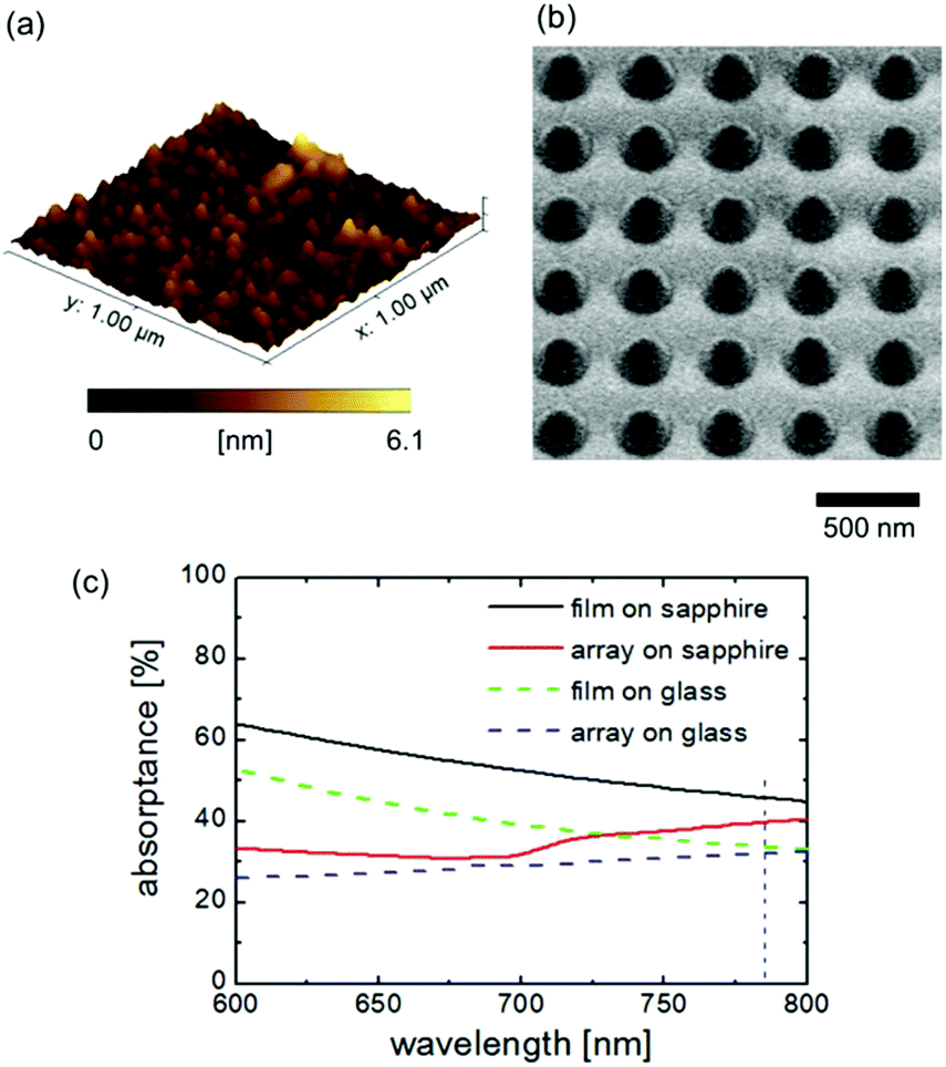 | ||
| Fig. 1 (a) AFM image of the TiN film sputtered on the sapphire substrate. (b) SEM image of the TiN array on the sapphire substrate. (c) Measured absorptance values of the TiN films and TiN arrays on the sapphire and glass substrates. The vertical dashed line indicates the optical heating wavelength of 785 nm. | ||
Fig. 1(c) shows the measured absorptance values of the film and array samples on the sapphire and glass substrates. Although the pillars on the glass substrate were a little larger than those on the sapphire substrate, the difference in optical properties was not significant. At the optical heating wavelength of 785 nm, the absorptance values of the film and array on the sapphire substrates were 46% and 40%, respectively. Similarly, the absorptance values of the film and array on the glass substrates at 785 nm were 34% and 32%, respectively. The relatively high absorptance values of the arrays, regardless of the smaller geometrical coverage compared to the films, were due to the broad plasmon resonance of the TiN. The transmittance and reflectance of the film and array samples are shown in Fig. S2 as the ESI.† The films were thick enough to block all incident light (transmittance ∼0), while the lower density of the arrays allowed 40–60% of the incoming light to be transmitted through the samples.
The temperature-dependent Stokes peaks for the film on the sapphire substrate are plotted in Fig. 2(a). The superstrate was air in this set of measurements. The temperature of the sample was controlled by a heater placed on the Raman microscope system. A rather broad peak centered at ∼558 cm−1 at 291 K (room temperature) corresponded to the optical phonon mode of nitrogen deficiencies.46,47 As the temperature increased, the peak blue shifted monotonically. A temperature-dependent blue shift for a TiN film was previously reported in ref. 48 and is well-known for semiconductors.49,50 A similar measurement was carried out for the array on the sapphire substrate, as shown in Fig. S3.† From these plots, the Raman peak positions were plotted against the temperatures of the samples as shown in Fig. 2(b). As expected, the plots for the film and array were the same within the experimental error; hence, the plot for the film was chosen and fitted by a fourth-order polynomial function. This fitted function was used to convert the Stokes peak shift into the temperature of the optically heated samples, as described in the following sections.
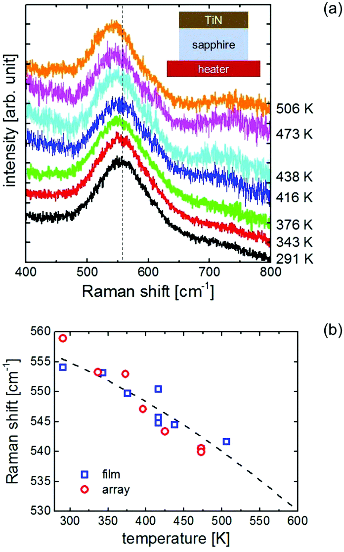 | ||
| Fig. 2 (a) Stokes peaks of the TiN film on a sapphire substrate at various temperatures heated by a sample heater with air as the superstrate. The dashed line shows the center position of the peak measured at 291 K. The temperature shown on the right is the temperature of the TiN film. (b) Raman shift of the Stokes peaks of the TiN film and TiN array as functions of the TiN temperature heated by a sample heater. The data for the film and array samples were collected from sub-figure (a) and Fig. S3,† respectively. The dashed line shows the fitted curve for the film data. | ||
The temperature increases of the film and array samples heated by the laser are presented in Fig. 3 where the superstrate was air for all the samples. Here, the incident 785 nm laser performed dual roles: optical heating and excitation of Raman scattering. The Stokes peak shifts were correlated to the temperature by the relationship presented in Fig. 2. The Stokes peaks for all four samples monotonically shifted to smaller wavenumbers, indicating that the samples were locally heated by laser irradiation.
 | ||
| Fig. 3 (a) Schematic diagram showing the four different samples (TiN film on the sapphire substrate, TiN array on the sapphire substrate, TiN film on the glass substrate, and TiN array on the glass substrate). (b) Laser power dependent temperature increase for the four samples in experiment. (c) Numerically simulated temperature increase of the four samples by laser heating. The top x-axes in panels (b) and (c) show the laser irradiance values which were calculated from the bottom x-axes considering the beam area. | ||
Fig. 3 shows that the difference between the film and array samples was small for the same substrates. This was expected, as the absorption of the films and array samples was of the same order, as shown in Fig. 1(c). TiN pillars convert light to heat more efficiently via enhanced light absorption, given the smaller volume of TiN for the array compared with the film. In addition, the thicknesses of the samples (160 nm) were more than three orders of magnitude thinner than those of the substrates (0.5 mm) so the substrates acted as effective heat sinks.
On the other hand, comparing the samples on the sapphire and glass substrates showed that the laser power dependence of the samples on glass was around six times higher than that of the samples on sapphire. As the dimensions of the two substrates were comparable with respect to the beam size (3.1 μm2), the heat transfer was dominated by the thermal properties of the substrates. The densities and heat capacities of the glass and sapphire were similar; hence the difference in heating was mainly due to the difference in thermal conductivities between the sapphire and glass. The thermal conductivity of sapphire (27 W (m K)−1) is ∼20 times higher than that of glass (1.4 W (m K)−1), resulting in a larger amount of heat being dissipated into the sapphire than into the glass.
To verify our assumption, the photothermal process was numerically simulated and solved under steady-state conditions using finite element method simulations. The temperatures of the films and arrays were averaged over the laser beam area and plotted in Fig. 3(b). Although the simulations slightly overestimated the temperatures compared to the experiments, the temperature increases of the samples on the glass substrates were larger than those on the sapphire substrates, validating the experimental results. The simulation also revealed that the heated region was more confined with the sapphire substrate than with the glass substrate as shown in Fig. S4.†
Next, each sample with a water superstrate covered by a cover slip was heated by using a 785 nm CW laser. The laser heating procedure was identical to the previous set of measurements. The results of this laser heating experiment are summarized in Fig. 4, along with the schematic diagrams of the sample setups. For the samples with sapphire substrates shown in Fig. 4(b), the temperature increases of the film and array samples were approximately linear with respect to the laser power up to ∼15 mW. Note that the laser heated area reached thermal equilibrium within the data accumulation period as shown in Fig. S5.† The slopes of the data were similar to those of the sapphire substrate samples with the air superstrate as shown in Fig. 3(b). This was expected, because the thermal conductivity of water is smaller than that of sapphire so the heat dissipation was governed mainly by the sapphire. However, when the laser power was increased above ∼20 mW the temperatures remained constant at ∼440 K. By further increasing the laser power, bubbles were observed at 68 mW and 70 mW for the film sample and array sample, respectively, (Fig. S6†) and the temperatures started to increase in accordance with the laser power. In accordance with the other studies done by using other substrates,7,8 Marangoni flows were observed after the bubble formation (see Fig. S7†). Since the boiling point of water is 373.15 K, the constant temperature regions were considered to be in superheated states.
 | ||
| Fig. 4 (a) Schematic diagrams of the TiN samples with sapphire substrates where the superstrates were water layers. (b) Laser power dependent temperature increase of the samples with sapphire substrates from the experiment. The dashed line and shaded region indicate the boiling point of water and the plateau region observed in the experiment, respectively. The vertical bar on the top left denotes the error bar in the temperature. (c) Schematic diagrams of the TiN samples with glass substrates where the superstrates were water layers. (d) Laser power dependent temperature increase of the samples with glass substrates from the experiment. The error range is identical to the error bar shown in panel (b). The top x-axes in panels (b) and (d) show the laser irradiance values which were calculated from the bottom x-axes considering the beam area. | ||
Water superheated by laser heating has been previously reported using an optical microscope; however, a constant temperature region has not been reported. Setoura et al. optically heated a gold nanoparticle on a sapphire substrate with a water superstrate.12 In their case, the maximum laser power was lower than that of ours, which we suggest is the reason why they did not observe a plateau region. One possible reason why such observations have not been made previously is that most studies used glass substrates. Since the thermal conductivity of glass is much lower than that of sapphire and comparable to that of water, the temperature of the heated nanostructures easily rose to high temperatures and the plateau region was not obvious. To confirm this hypothesis, the samples with the glass substrates were also laser heated in the same manner and the results are plotted in Fig. 4(d). Unlike the use of sapphire substrates, a plateau region did not appear, consistent with the work done by others.5,6,14 Nonetheless, even with the glass substrates plateau regions seem to be observed by recording the temperature at a smaller step as shown in Fig. S8.† Compared to the plateau regions with the sapphire substrate, the plateau regions with the glass substrates are in a much limited power range, which could be the reason that they were previously overlooked.
Bubbles were observed when laser powers of 5 mW and 11 mW were used for the film and array samples on the glass substrate, respectively (see Fig. S6†), much lower powers than those for the samples on sapphire substrates. For both laser powers, the temperatures were well above the boiling point of water, indicating superheating. Similar to the cases with the sample with the sapphire substrates, Marangoni flows were observed by further increasing the power as shown in Fig. S7.†
To investigate whether the observed plateau region is specific to water, identical experiments were performed by replacing water with EG or PGMEA having boiling points of 470.45 and 419.15 K, respectively. In this set of experiments, the film and array samples with sapphire substrates were used. The results of the laser heating for samples having either EG or PGMEA superstrate are shown in Fig. S9.† Even if the superstrate was either EG or PGMEA, there were plateau regions similar to the case with water. With the EG or PGMEA superstrate, bubbles were not observed probably because their boiling points are higher than that of water and our laser was not powerful enough to generate bubbles.
From Fig. 4 and S9,† the existence of a constant temperature region for a sample having a liquid superstrate seems to be a common feature if the substrate is sapphire. The reason is considered to be related to the latent heat of evaporation. In experiment, the fact that the plateau temperature (∼440 K for water, ∼480 K for PGMEA, and ∼520 K for EG) scales with the boiling temperature (373.15 K for water, 419.15 K for PGMEA, and 470.45 K for EG) suggests the effect of latent heat. When the laser power was increased so that the optically supplied energy exceeds the latent heat, the temperature rose again together with the formation of bubbles as shown for the results with the water superstrate.
Maintaining nearly constant temperatures, even at elevated laser power, provides a unique environment for various applications. For instance, if a sapphire substrate is used in an optical tweezer,51 the trapping force can be several times stronger than the standard case below explosive bubble formation. Additionally, one could envision to replace sapphire with a material having even higher thermal conductivity such as copper so that the constant temperature region can be further extended.
Conclusions
In summary, we experimentally measured the local temperatures of the TiN films and arrays with different substrates and superstrates by Raman spectroscopy. The substrates used in our work were glass and sapphire, and water, EG, and PGMEA were the tested liquids which have different boiling points. In contrast to conventional Raman spectroscopy-based temperature sensing, our method uses the temperature-dependent Stokes peak shift of TiN and does not require measurement of anti-Stokes peaks. Our results demonstrated that the thermal conductivity of the substrate is an important parameter for tuning the local temperature during laser heating of nanostructures. When the superstrate and substrate were liquid and sapphire, respectively, the liquid could be kept at a constant temperature above its boiling point over a certain range of laser power. This is a unique superheating condition which has not been previously reported. Additionally, similar superheating can be seen with the glass substrate, however, the range of the laser power was narrower compared to that with the sapphire substrate. We anticipate that TiN nanostructures will be useful platforms for studying microscale photothermal effects, where optimizing the choice of a substrate can broaden the application of laser heating, particularly using liquids, and provide insight into unexplored mechanisms.Experimental
Sample fabrication and optical properties
The TiN films were fabricated using a DC magnetron sputtering apparatus on two sapphire substrates and two silica glass substrates. The sizes of the sapphire and glass substrates were roughly 15 × 15 mm2 and 30 × 30 mm2, respectively, and were 0.5 mm thick. During sputtering, nitrogen and argon gas were added and the sample holder was heated to 520 K. The film thickness in the current study is 160 nm. The TiN films on the sapphire and glass substrates were taken for nanoarray fabrication. After spin-coating a resist (TU2-170, Obducat. Ltd) on each film, the pre-baked samples were patterned by the nanoimprint lithography technique (EitreTM 3, Obducat) using a silicon mold. The mold has a square lattice pattern of 400 nm periodicity and the height and diameter of the pillars are 200 nm and 150 nm, respectively. Then, the samples were etched by using a reactive ion etching instrument (RIE-101iPH, Samco) using a mixture of argon, BCl3 and chlorine.Characterization
The film roughness and geometry were characterized by using an atomic force microscope (SPI3800N, Seiko Instruments Inc.) and a scanning electron microscope (SU8000, Hitachi), respectively. The optical properties of the samples were determined by using a UV-Vis spectrometer (V-570, JASCO).To calibrate the Stokes peak shift with respect to the temperature, the films and arrays were heated by a sample heater (10064, Japan High Tech) placed on the sample stage of a Raman microscope (T64000, Horiba-Jovin Yvon). The sample was excited by using a He–Ne laser at ∼3 mW with an objective lens (90×, NA0.7). The surface temperature of the sample was monitored by using a K-type thermocouple and the Stokes peaks were recorded by gradually increasing the temperature up to ∼500 K. The temperature calibration curve is extrapolated up to 700 K assuming no property changes in TiN.
Optical heating and temperature monitoring
For the local heating experiment, another Raman microscope (alpha 300S, WITec) was used which was equipped with a monochromator (ACTON SP2300, Princeton Instruments) and a CCD (DU401A, Andor). The excitation source was a CW 785 nm diode laser (XTRA, Toptica), and the excitation and collection were done by using an objective lens (50×, NA0.8, Olympus). The laser power was measured right after the objective lens.The sample was placed on the sample stage of the microscope. When the superstrate was liquid, 20 μL of each liquid was dropped on the sample and covered by a cover slip before placing the sample on the same sample stage. The liquids investigated in this study were pure water, EG, and PGMEA.
Author contribution
R.K, H.S., and S.M. fabricated the samples. S.I., R.K., H.S. T.D.D., S.S., K.N. M.S. and T.N. conducted the optical measurements. S.I. performed the numerical simulations. All the authors discussed the results and contributed to manuscript preparation.Conflicts of interest
There are no conflicts to declare.Acknowledgements
The authors thank S. Goya for his help in experiment. The sample preparation was partially supported by the Nanotechnology Hub, Kyoto University, and NIMS Nanofabrication Platform in the “Nanotechnology Platform Project” sponsored by MEXT. S. I. and S. M. gratefully acknowledge the support from Nanotech CUPAL. This work was supported by JSPS KAKENHI (15K17447, 16H04217, 16H06364, 17H04801, and 17K19045), CREST “Phase Interface Science for Highly Efficient Energy Utilization” (JPMJCR13C3), PRESTO “Hyper-nano-space design toward Innovative Functionality” (JPMJPR131B), and Japan Prize Foundation.References
- G. Baffou and R. Quidant, Laser Photonics Rev., 2013, 7, 171–187 CrossRef CAS.
- M. L. Brongersma, N. J. Halas and P. Nordlander, Nat. Nanotechnol., 2015, 10, 25–34 CrossRef CAS PubMed.
- C. Loo, A. Lin, L. Hirsch, M.-H. Lee, J. Barton, N. Halas, J. West and R. Drezek, Technol. Cancer Res. Treat., 2004, 3, 33–40 CrossRef CAS PubMed.
- K. Setoura, D. Werner and S. Hashimoto, J. Phys. Chem. C, 2012, 116, 15458–15466 CrossRef CAS.
- D. Hühn, A. Govorov, P. R. Gil and W. J. Parak, Adv. Funct. Mater., 2012, 22, 294–303 CrossRef.
- G. Baffou, J. Polleux, H. Rigneault and S. Monneret, J. Phys. Chem. C, 2014, 118, 4890–4898 CrossRef CAS.
- K. Namura, K. Nakajima, K. Kimura and M. Suzuki, Appl. Phys. Lett., 2015, 106, 043101 CrossRef.
- R. Muruganathan, Y. Zhang and T. M. Fischer, J. Am. Chem. Soc., 2006, 128, 3474–3475 CrossRef CAS PubMed.
- V. Kotaidis, C. Dahmen, G. v. Plessen, F. Springer and A. Plech, J. Chem. Phys., 2006, 124, 184702 CrossRef CAS PubMed.
- E. Lukianova-Hleb, Y. Hu, L. Latterini, L. Tarpani, S. Lee, R. A. Drezek, J. H. Hafner and D. O. Lapotko, ACS Nano, 2010, 4, 2109–2123 CrossRef CAS PubMed.
- M. T. Carlson, A. J. Green and H. H. Richardson, Nano Lett., 2012, 12, 1534–1537 CrossRef CAS PubMed.
- K. Setoura, Y. Okada, D. Werner and S. Hashimoto, ACS Nano, 2013, 7, 7874–7885 CrossRef CAS PubMed.
- L. Hou, M. Yorulmaz, N. R. Verhart and M. Orrit, New J. Phys., 2015, 17, 013050 CrossRef CAS.
- A. A. Alaulamie, S. Baral, S. C. Johnson and H. H. Richardson, Small, 2017, 13, 1601989 CrossRef PubMed.
- M. Enders, S. Mukai, T. Uwada and S. Hashimoto, J. Phys. Chem. C, 2016, 120, 6723–6732 CrossRef CAS.
- E. Y. Lukianova-Hleb and D. O. Lapotko, Nano Lett., 2009, 9, 2160–2166 CrossRef CAS PubMed.
- K. Namura, M. Suzuki, K. Nakajima and K. Kimura, Opt. Lett., 2011, 36, 3533–3535 CrossRef PubMed.
- S. Hashimoto, D. Werner and T. Uwada, J. Photochem. Photobiol., C, 2012, 13, 28–54 CrossRef CAS.
- D. Steinmüller-Nethl, R. Kovacs, E. Gornik and P. Rödhammer, Thin Solid Films, 1994, 237, 277–281 CrossRef.
- M. B. Cortie, J. Giddings and A. Dowd, Nanotechnology, 2010, 21, 115201 CrossRef CAS PubMed.
- G. V. Naik, J. Kim and A. Boltasseva, Opt. Mater. Express, 2011, 1, 1090–1099 CrossRef CAS.
- G. V. Naik, V. M. Shalaev and A. Boltasseva, Adv. Mater., 2013, 25, 3264–3294 CrossRef CAS PubMed.
- W. Synielnikowa, T. Niemyski, J. Panczyk and E. Kierzek-Pecold, J. Less-Common Met., 1971, 23, 1–6 CrossRef CAS.
- H. von Seefeld, N. W. Cheung, M. Maenpaa and M.-A. Nicolet, IEEE Trans. Electron Devices, 1980, 27, 873–876 Search PubMed.
- J. Pflüger, J. Fink, W. Weber, K. P. Bohnen and G. Crecelius, Phys. Rev. B: Condens. Matter Mater. Phys., 1984, 30, 1155–1163 CrossRef.
- S. Bagheri, C. M. Zgrabik, T. Gissibl, A. Tittl, F. Sterl, R. Walter, S. De Zuani, A. Berrier, T. Stauden, G. Richter, E. L. Hu and H. Giessen, Opt. Mater. Express, 2015, 5, 2625–2633 CrossRef CAS.
- S. Murai, K. Fujita, Y. Daido, R. Yasuhara, R. Kamakura and K. Tanaka, Opt. Express, 2016, 24, 1143–1153 CrossRef CAS PubMed.
- A. Lalisse, G. Tessier, J. Plain and G. Baffou, Sci. Rep., 2016, 6, 38647 CrossRef CAS PubMed.
- U. Guler, J. C. Ndukaife, G. V. Naik, A. A. Nnanna, A. V. Kildishev, V. M. Shalaev and A. Boltasseva, Nano Lett., 2013, 13, 6078–6083 CrossRef CAS PubMed.
- W. Li, U. Guler, N. Kinsey, G. V. Naik, A. Boltasseva, J. Guan, V. M. Shalaev and A. V. Kildishev, Adv. Mater., 2014, 26, 7959–7965 CrossRef CAS PubMed.
- U. Guler, S. Suslov, A. V. Kildishev, A. Boltasseva and V. M. Shalaev, Nanophotonics, 2015, 4, 269–276 CAS.
- S. Ishii, R. P. Sugavaneshwar and T. Nagao, J. Phys. Chem. C, 2016, 120, 2343–2348 CrossRef CAS.
- S. Ishii, K. Uto, E. Niiyama, M. Ebara and T. Nagao, ACS Appl. Mater. Interfaces, 2016, 8, 5634–5640 CrossRef CAS PubMed.
- O. Anjaneyulu, S. Ishii, T. Imai, T. Tanabe, S. Ueda, T. Nagao and H. Abe, RSC Adv., 2016, 6, 110566–110570 RSC.
- M. Kaur, S. Ishii, S. L. Shinde and T. Nagao, ACS Sustainable Chem. Eng., 2017, 5(10), 8523–8528 CrossRef CAS.
- U. Guler, A. V. Kildishev, A. Boltasseva and V. M. Shalaev, Faraday Discuss., 2015, 178, 71–86 RSC.
- Z. Fang, Y.-R. Zhen, O. Neumann, A. Polman, F. J. García de Abajo, P. Nordlander and N. J. Halas, Nano Lett., 2013, 13, 1736–1742 CrossRef CAS PubMed.
- D. Ross, M. Gaitan and L. E. Locascio, Anal. Chem., 2001, 73, 4117–4123 CrossRef CAS PubMed.
- T.-C. Liu, Z.-L. Huang, H.-Q. Wang, J.-H. Wang, X.-Q. Li, Y.-D. Zhao and Q.-M. Luo, Anal. Chim. Acta, 2006, 559, 120–123 CrossRef CAS.
- A. Gupta, R. S. Kane and D.-A. Borca-Tasciuc, J. Appl. Phys., 2010, 108, 064901 CrossRef.
- M. L. Clarke, S. G. Chou and J. Hwang, J. Phys. Chem. Lett., 2010, 1, 1743–1748 CrossRef CAS.
- S. L. Shinde and K. K. Nanda, Angew. Chem., Int. Ed., 2013, 52, 11325–11328 CrossRef CAS PubMed.
- K. Yamamoto, R. Togawa, R. Fujimura and K. Kajikawa, Opt. Express, 2016, 24, 19026–19031 CrossRef CAS PubMed.
- J. Christofferson and A. Shakouri, Rev. Sci. Instrum., 2005, 76, 024903 CrossRef.
- G. Baffou, P. Bon, J. Savatier, J. Polleux, M. Zhu, M. Merlin, H. Rigneault and S. Monneret, ACS Nano, 2012, 6, 2452–2458 CrossRef CAS PubMed.
- W. Spengler and R. Kaiser, Solid State Commun., 1976, 18, 881–884 CrossRef CAS.
- W. Spengler, R. Kaiser, A. N. Christensen and G. Müller-Vogt, Phys. Rev. B: Condens. Matter Mater. Phys., 1978, 17, 1095–1101 CrossRef CAS.
- I. Dreiling, A. Haug, H. Holzschuh and T. Chassé, Surf. Coat. Technol., 2009, 204, 1008–1012 CrossRef CAS.
- M. Balkanski, R. Wallis and E. Haro, Phys. Rev. B: Condens. Matter Mater. Phys., 1983, 28, 1928 CrossRef CAS.
- J. Menéndez and M. Cardona, Phys. Rev. B: Condens. Matter Mater. Phys., 1984, 29, 2051–2059 CrossRef.
- P. A. Quinto-Su, Nat. Commun., 2014, 5, 5889 CrossRef CAS PubMed.
Footnote |
| † Electronic supplementary information (ESI) available: SEM image of the TiN array on the glass substrate; optical properties of the TiN films and TiN arrays; Stokes peaks of the array on the sapphire substrate; simulated temperature profiles; time dependence of the sapphire substrate samples; optical images of the bubbles; optical images of the Marangoni flows; laser power dependences of the sapphire substrate samples with the EG superstrate or PGMEA superstrate; description on the heat transfer simulation. See DOI: 10.1039/c8nr05931d |
| This journal is © The Royal Society of Chemistry 2018 |