 Open Access Article
Predicting the conductance of strongly correlated molecules: the Kondo effect in perchlorotriphenylmethyl/Au junctions†
W. H.
Appelt‡
ab,
A.
Droghetti‡
c,
L.
Chioncel
 bd,
M. M.
Radonjić
e,
E.
Muñoz
 f,
S.
Kirchner
g,
D.
Vollhardt
d and
I.
Rungger
 h
h
aTheoretical Physics II, Institute of Physics, University of Augsburg, D-86135 Augsburg, Germany
bAugsburg Center for Innovative Technologies, University of Augsburg, D-86135 Augsburg, Germany
cNano-Bio Spectroscopy Group and European Theoretical Spectroscopy Facility (ETSF), Centro de Fisica de Materiales, Universidad del Pais Vasco, Avenida Tolosa 72, 20018 San Sebastian, Spain
dTheoretical Physics III, Center for Electronic Correlations and Magnetism, Institute of Physics, University of Augsburg, D-86135 Augsburg, Germany
eScientific Computing Laboratory, Center for the Study of Complex Systems, Institute of Physics Belgrade, University of Belgrade, Pregrevica 118, 11080 Belgrade, Serbia
fFacultad de Fisica, Pontificia Universidad Católica de Chile, Casilla 306, Santiago 22, Chile
gZhejiang Institute of Modern Physics, Zhejiang University, Hangzhou, Zhejiang 310027, China
hNational Physical Laboratory, Teddington, TW11 0LW, UK. E-mail: ivan.rungger@npl.co.uk
First published on 13th September 2018
Abstract
Stable organic radicals integrated into molecular junctions represent a practical realization of the single-orbital Anderson impurity model. Motivated by recent experiments for perchlorotriphenylmethyl (PTM) molecules contacted to gold electrodes, we develop a method that combines density functional theory (DFT), quantum transport theory, numerical renormalization group (NRG) calculations and renormalized super-perturbation theory (rSPT) to compute both equilibrium and non-equilibrium properties of strongly correlated nanoscale systems at low temperatures effectively from first principles. We determine the possible atomic structures of the interfaces between the molecule and the electrodes, which allow us to estimate the Kondo temperature and the characteristic transport properties, which compare well with experiments. By using the non-equilibrium rSPT results we assess the range of validity of equilibrium DFT + NRG-based transmission calculations for the evaluation of the finite voltage conductance. The results demonstrate that our method can provide qualitative insights into the properties of molecular junctions when the molecule–metal contacts are amorphous or generally ill-defined, and that it can further give a fully quantitative description when the experimental contact structures are well characterized.
1. Introduction
Molecular electronics holds great promise for future applications in computing, sensing, clean-energy, and even data-storage technologies.1–3 However, a general difficulty so far has been the poor characterization of the device structures and their relationship with the measured conductances and functionalities. For this problem, ab initio simulations based on density functional theory (DFT)4 have proven very successful in supporting experiments, and they have played a key role in advancing the field during the last decade.5–9 Yet, standard DFT-based transport schemes for simulations of experimental molecular junctions have several limitations. The most prominent of these is the failure to account for the strong electron correlations leading to the Kondo effect in devices comprising magnetic molecules, and rigorous treatments and extensions overcoming this problem are currently under active development.10–15In this article, we establish a suitable combination of DFT and many-body techniques to achieve an unprecedented quantitative description of the equilibrium and non-equilibrium conductance of molecular devices showing Kondo effect. By using gold/perchlorotriphenylmethyl (PTM)/gold junctions as a specific example we relate the Kondo temperature to the electrode–molecule contact geometries, thus matching the range of variability of the experimental results.16 Furthermore we address the dependence of the conductance at finite temperature and extend the method to finite bias.
Our multi-scale approach combines DFT, non-equilibrium Green's functions (NEGF),17 numerical renormalization group (NRG) methods,18–21 and renormalized superperturbation theory (rSPT).22,23 First the contact geometry and electronic structure of molecular junctions are obtained by DFT + NEGF. Then the DFT Kohn–Sham (KS) states are projected onto an effective Anderson impurity model,24–33 which is solved exactly to obtain the Kondo temperature and the equilibrium zero-temperature conductance via NRG. Based on these results we finally compute the non-equilibrium rSPT transport coefficients, which encode the behavior of the junctions at low temperature, finite magnetic field, and finite bias voltage.22
Stable organic radicals contacted to metal electrodes, such as the PTM molecule on Au, form a practical realization of the prototypical single-orbital Anderson impurity model,16,31,34,35 and are therefore ideally suited to study the fundamental aspects of the interaction of magnetic impurities with metallic surfaces. These aspects include the interplay between the binding geometry and the energy level alignment with respect to the surface Fermi energy, as well as the electron correlations leading to the Kondo effect.
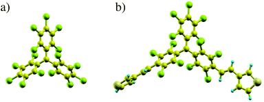
In recent experiments16,36 PTM-radicals were functionalized with thiophene linkers producing the PTM-bis-thiophene radical (called PTM-BT in the following to distinguish it from the bare PTM; see also Fig. 1 for their atomic structures). These molecules were then integrated into gold mechanically-controlled break-junctions (MCBJs) and gold electromigrated break-junctions (EMBJs) to measure their transport properties. While at room temperature very low conductance values were reported,36 at low temperature a zero-bias conductance resonance was observed in many of the junctions, and its Kondo character verified by temperature- and magnetic field-dependent measurements.16 The low-temperature results indicate that the PTM radical can preserve the unpaired spin in a solid state three-terminal configuration, and that it is stable under mechanical stretching of the electrodes. One of the remarkable features is the rather high Kondo temperature of about 3 K, which is largely constant upon stretching of the junction. This implies that for the junctions that exhibiting Kondo behavior the contact of the molecule to one of the electrodes is very strong, and is not affected by the elongation of the junction in the MCBJ process. In contrast, the background conductance shows large variations. This can happen upon stretching when the contact to the second electrode varies significantly, or else when one of the two electrodes changes its Au–Au bond conformation significantly.37,38 Overall the low-temperature experimental results point to a structure with highly asymmetric coupling to the electrodes. In the following we will show that this hypothesis is indeed confirmed by our calculations, thus providing a detailed understanding of the electronic and transport properties of the PTM/gold junctions at the atomic scale.
The paper is organized as follows. We first discuss the equilibrium DFT results for a number of possible junction structures (section 2), and then provide estimates for the Kondo temperature for these geometries (section 3). For a set of geometries we then present the linear response transport properties including the strong electron–electron correlations obtained by DFT + NEGF + NRG (section 4) and finally extend the results to finite temperature and finite bias via rSPT (section 5).
2. DFT calculations
PTM has a propeller-like structure with a central carbon atom coordinated by the three phenyl rings. In the gas phase, it has the typical electronic structure of a radical.39–41 The energy spectrum has doubly occupied electronic states filled up to the highest occupied molecular orbital (HOMO). Above the HOMO there is a further well-separated, singly occupied molecular orbital (SOMO) with an unpaired electron, giving a total molecular spin quantum number of 1/2. In the PTM, the charge isosurface indicates that the SOMO is mainly confined to the central carbon, while the HOMO and the lowest unoccupied molecular orbital (LUMO) are largely located on the rest of the molecule. This is presented more extensively in the ESI section S2,† while the computational details of our DFT calculations are given in the ESI section S1.† The difference between the ionization potential and electron affinity of the molecule defines the fundamental gap and corresponds to the charging energy U. In the absence of any experimental results, we calculate U via total energy differences42 to be about 4 eV. PTM-BT has a very similar electronic structure to that of the bare PTM, although the SOMO is slightly delocalized over the thiophene ligands,16 and this results in a charging energy smaller by about 0.4 eV. Note that when the molecule is placed between Au electrodes there is a significant renormalization of the energy levels and consequently a reduction of the charging energy, which we discuss in section S2 of the ESI as well as in section 3.2.†In order to understand the electronic structure of the molecule/Au contact and how this determines the key parameters affecting the Kondo temperature, we consider a number of qualitatively different model structures, which are shown in Fig. 2.
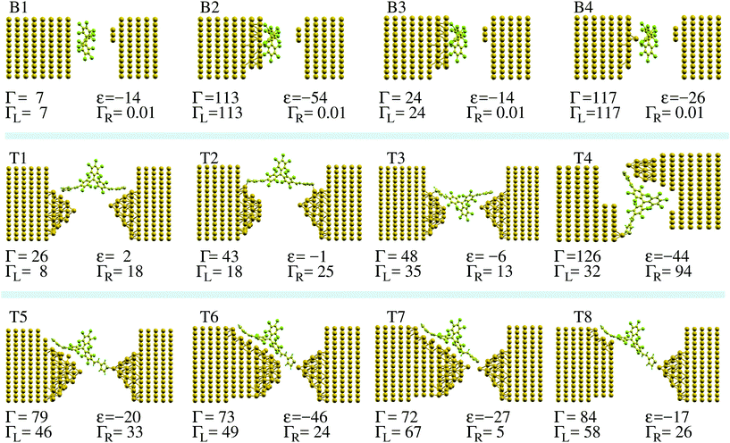
To start, we look at the ideal case of a bare PTM molecule on a flat Au(111) surface, which we denote as configuration (CFG) B1 in Fig. 2. The 3-atom Au tip is placed at a rather large distance, so that the electronic coupling between the molecule and the tip is negligible with respect to that to the substrate. Since in MCBJ and EMBJ experiments the Au stretched surface is expected to be highly corrugated rather than perfectly flat,37,38 we then model a rough Au surface by removing a number of Au atoms from the perfect Au(111) surface (CFGs B2 to B4). Finally, we consider a number of break-junction setups comprising PTM-BT (CFGs T1 to T8). The detailed contact structure is expected to be different for each individual experimental conductance trace measurement. The model junctions considered here include cases with both symmetric and asymmetric molecule–electrodes coupling. For some structures the PTM central core is located inside the junction's empty gap, whereas for other structures it is physisorbed on one of the electrodes. Furthermore, the thiophene linkers can be connected to the electrodes either non-covalently or covalently via a sulfur–Au adatom direct bond.
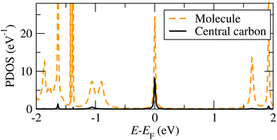
A representative DFT projected density of states (PDOS) is shown in Fig. 3 (see ESI section S1† for the computational details). When the molecule is in contact with the Au electrodes, the SOMO DOS can be modeled approximately by a half-filled Lorentzian-like peak close to the Fermi energy, EF. Note that while we refer to the state as SOMO also when the molecule is on the Au substrate for consistency, its occupation can generally deviate from one in this case. The full width at half maximum (FWHM) of the SOMO peak corresponds to its electronic coupling to the Au substrate, Γ,24 which can be calculated by using the projection scheme recently developed in ref. 24. The results for each model geometry considered are indicated in Fig. 2 along with the DFT SOMO on-site energy, ε, relative to EF. These values are the parameters required for the evaluation of the Kondo temperature.
As a matter of notation we label the structures with the propeller-like PTM parallel (perpendicular) to the surface, as “parallel” (“perpendicular”) configurations. For the idealized case of a bare PTM on a flat Au(111) surface, we find that the molecule is physisorbed with an energy difference between the “parallel” configuration (B1) and the “perpendicular” configuration (not shown) of about 335 meV, favoring the “parallel” configuration. The equilibrium position of the central C atom is located at about 5.18 Å from the top Au layer. For this configuration there is a negligible charge-transfer from the surface to the molecule, and the PTM preserves its unpaired electron, with Γ ≈ 7 meV and therefore very small.
On the corrugated surface (CFG B2) the molecule can bind better to the Au, since part of its phenyl rings can move into regions where the Au surface has a dip. In CFG B2 an Au atom is located below the central C atom of the bare-PTM. This atom is then removed in the CFG B3, while it is kept as the only atom from the top-most Au surface in the CFG B4. Comparing the Γ-values for these structures allows us to estimate the effect of Au atoms directly in contact with the central C atom of the PTM. For CFG B2 we find the occupation of the SOMO to be 1.40 electrons, indicating that a partial electron transfer between the gold and the molecule has occurred. In fact, the SOMO DOS peak lies below EF (ε = −54 meV). The increased charge transfer indicates an increased screening of the transferred electrons by the Au surface atoms, which is due to the molecule moving closer to the Au surface, in particular to the Au atom closest to the core of the PTM molecule. In general an increase in the screening also leads to a reduction of U (see the discussion in the ESI section S2†). We note that the results for the charge transfer obtained for non-spin-polarized calculations are approximately the same as those obtained in spin-polarized calculations in the ESI section S2.† The electronic coupling of 114 meV for CFG B2 is much larger than the one for the PTM on flat Au(111). An analysis of the origin of such a large coupling shows that it is mainly due to the Au atom underneath the central C atom of the PTM. In fact, for CFG B3, where this central Au adatom is removed, the coupling drops to 23 meV, while it remains large for CFG B4, where only this Au adatom is kept of the top Au surface layer.
Finally, we consider the model break-junctions (CFGs T1 to T8). In these cases, we use only the “perpendicular” configuration, since the “parallel” PTM-BT configuration would require very large simulation cells, which are beyond our current computing resources. The results allow us to infer the general trends for the electronic coupling of the radical center to the Au electrodes through the thiophene linkers (see Fig. 2). As can be seen the computed values of Γ vary over almost one order of magnitude, from 26 to 126 meV. We note that in break-junctions Γ is the sum of two contributions, ΓL and ΓR, representing the electronic coupling to the left and right lead, which we calculate individually with the method outlined in ref. 24. In general we find that ΓL or ΓR are large when there are Au atoms close to the thiophene linkers, such as for ΓL in CFG T7. A bond between the sulfur atoms and a protruding Au atom also increases the coupling. On the other hand, the coupling is low when such a bond is absent, and when the angle between the thiophene and the Au is larger, such as for ΓL in CFG T1.
3. Kondo effect
3.1. Formulation of the single impurity Anderson problem
The PTM in contact with the leads is modeled by a single impurity Anderson Model (SIAM), which has the Hamiltonian43| HSIAM = Hd + Hc + Hhyb, | (1) |
where Hd describes the electrons of spin σ localized at the impurity site, which are created (annihilated) by the operator d†σ (dσ), with ndσ = d†σdσ being the corresponding number operator; εd is the orbital energy, U the charging energy, and
 the occupation, where the bracket 〈⋯〉 denotes the thermal expectation value. For the PTM molecule the impurity site is the SOMO. Note that εd does not coincide with ε in Fig. 3, since the on-site Coulomb interaction is already partially accounted for in KS-DFT, and this contribution has to be subtracted, so that εd = ε − εdc.24,44 Here εdc is the so-called double counting correction, whose exact expression is not known except for certain limiting cases, and several approximations have been introduced in the literature.45 In general εdc depends on U, and in the commonly used “fully localized limit” it is given by εdc = U(nDFTd−1/2),12 where nDFTd is the DFT occupation of the impurity. A comprehensive discussion of the difficulties arising when combining DFT with such an Anderson impurity model and more generally the dynamical mean field theory is given in ref. 45 and 46. Note that instead of the Anderson impurity model one can also use other methods to treat the highly correlated subsystem, such as for example embedded correlated wavefunction schemes.47,48 A review of the advantages and limitations of various embedding schemes that link many-body calculations for a subsystem to an environment treated at the DFT level is given in ref. 49.
Since in an experimental setting the occupation can be set by applying a gate voltage, here we treat εd as an adjustable parameter, independent of the DFT results, and choose its value to ensure a specified occupation of the impurity orbital. We will also investigate how the results depend on the charging energy U, and will provide estimates of possible values of U for PTM/Au geometries.
In eqn (1)Hc describes the effective bath of electrons with momentum k and spin σ, which are created (annihilated) by the operator c†k, σ (ck,σ) and with number operator nk,σ = c†k,σck,σ. The effective bath includes the electrons in the Au leads, as well as those in the molecular orbitals, except for the SOMO. We note that the chemical potential in the Hamiltonian eqn (1) is set to zero by shifting both the bath and impurity energies εd and εk by an additive constant. This does not affect the properties of the system. Furthermore, in zero-temperature calculations we will refer to the chemical potential μ = 0 as the Fermi energy EF = 0, which is most commonly used in first principles calculations.
Finally, Hhyb accounts for the hybridization between the bath and the impurity, with Vk corresponding to the hybridization matrix element. Accordingly, we can define the hybridization function Δ(E) = ReΔ(E) + iImΔ(E), with
 | (2) |
 | (3) |
3.2. Estimation of the Kondo temperature
In order to obtain a first estimate of the Kondo temperature for different junctions presented in Fig. 2, we assume a constant (energy independent) coupling Γ = Γ(EF = 0). The Anderson model then maps onto the Kondo model while approaching the so-called local moment limit, where |εd| ≫ Γ and |εd + U| ≫ Γ, (nd ≈ 1)50 (see ESI section S3† for details), and the Kondo temperature is given by the Haldane equation51,52 | (4) |
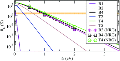 | ||
| Fig. 4 Kondo temperature, θL, as function of the charging energy, U, obtained using eqn (4) with εd = −U/2, and NRG solutions for the exact system- and energy-dependent hybridization function. The corresponding electrodes–molecule configurations are illustrated in Fig. 2. The horizontal orange region illustrates the experimental range of Kondo temperatures of about 1–3 K.16 | ||
Experimentally it is found that θL is approximately constant upon stretching of the junction, which indicates a highly asymmetric coupling, where the molecule preserves the contact geometry to one electrode, while the contact with the other electrode is elongated. In other words, the molecule is strongly bound to one of the electrodes, which may correspond to the core of the PTM-BT lying flat on a rough Au surface with the thiophene linkers bridging both sides of the junction.
This conclusion is supported by calculations for the CFGs B2, B4 and T4 structures, which have the largest values of Γ, and which all show asymmetric couplings. The calculated θL values lie in the experimental range if U is equal to about 1 eV. This charging energy is considerably smaller than the gas phase value of about 4 eV, and we ascribe this reduction of U to the charge screening by the electrons in the Au surface (see ESI section S2†). A value for the change of U due to screening can be calculated using a number of methods,53 for molecules on general corrugated and irregular metal surfaces constrained DFT (cDFT) has been shown to give good results.54,55 Alternatively, here we estimate it by approximating the metal surface as a plane, and by using a classical image charge model with a molecule between two metal electrodes54 to capture this effect. In this way we calculate that a gap reduction of about 3 eV corresponds to ideal planar Au electrodes at a distance of about 2.7 Å from the center of the molecule. This number is similar to the distance of 3.4 Å for the CFG B2 structure. The remaining difference can be due to either an overestimated theoretical gas phase gap, or due to the experimental atomic structures having an even stronger binding between molecule and electrodes than CFG B2.
For the structures with small Γ the value of U that brings θL in the experimental range is very small, and goes below the expected possible range. Such junctions are therefore expected to exhibit a θL well below the experimentally accessible temperatures. This is consistent with the experimental evidence that only a fraction of the molecular junctions, which we attribute to those with the largest Γ, exhibit a Kondo state at an experimentally accessible temperature. Overall our results confirm that the molecule lies flat on a rough Au surface when it exhibits Kondo behavior, since only such structures allow for small binding distances and strong electronic coupling.
3.3. NRG calculations
In order to confirm the trends for θL obtained with the simplified model eqn (4), and to evaluate the conductance in the presence of electronic correlations, we integrate NRG calculations in the method. We consider the SIAM representing the PTM/Au structures with the largest Γ (CFGs B2, B4 and T4), for which in the previous subsection have estimated the Kondo temperatures to lie in the experimental range. For each junction we calculate ImΔ(E) in eqn (2) by using DFT + NEGF with the method presented in ref. 24, and the results are shown in Fig. 5. While the value around EF is similar for all cases, there are pronounced differences in the energy dependence. The NRG calculations then allow us to verify whether the approximation of a constant Γ used so far is applicable for these realistic atomic structures. The real part is obtained with the Kramers–Kronig relation, eqn (3). Further details about the NRG calculations are presented in the ESI section S4.† The many-body self-energy calculated with NRG is then used to evaluate the zero-bias and zero-temperature transmission in the presence of strong correlations in the next section.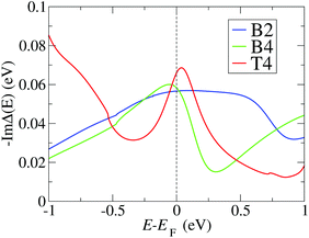 | ||
| Fig. 5 Negative imaginary part of the hybridization function calculated using the DFT + NEGF method, and used as input for the NRG calculation, for the three configurations with the largest hybridizations (B2, B4, T4) (see Fig. 2). High energy contributions are truncated as outlined in the ESI section S4.† | ||
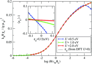
The Kondo temperature is extracted from the impurity contribution to the magnetic susceptibility χs(θ)19 (see ESI section S5†). In Fig. 6 we present χs(θ) for the B4 geometry, where the inset shows the small deviation of the impurity occupation nd from the half-filled case (nd = 1). We find that χs(θ) always follows the same universal behavior as long as the interaction strength is large enough (U > 0.5 eV). A crossover is observed from the high θ local moment regime, where kBθχs/(gμB)2 = 1/4, to the low θ strong correlation limit, where kBθχs/(gμB)2 = 0; here g is the Landè-factor and μB the Bohr magneton.19 We find that for U values above U = 0.5 eV the curves can be collapsed onto a single universal function. Note that for U = 0.5 eV one can already recognize the deviation from the universal behavior as a dip in the high θ susceptibility.
The collapse of the susceptibilities is interpreted as a universality due to the formation of a Kondo-singlet. In the local moment regime the static spin-susceptibility scaled by the Kondo-temperature follows the same universal curve,20 where the scaling function F(x) is defined by51
 | (5) |
4. Electron transmission
To evaluate the transport properties of this system we add the zero-temperature NRG self-energy, Σ(E, θ = 0), to the DFT + NEGF Green's function via the Dyson equation and compute the resulting energy-dependent transmission function, Tt(E, θ = 0), in the presence of many-body correlations not captured at the standard DFT-KS level.24,29,30 As outlined in the ESI sections S7 and S8,† the linear response zero-temperature conductance, G0 = G(V = 0, θ = 0) = dI(V, θ = 0)/dV|V = 0, is given by: | (6) |
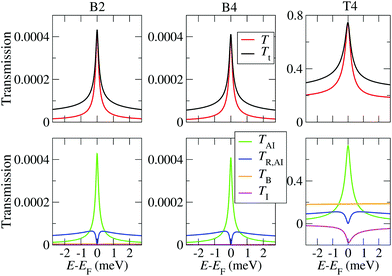
As outlined in ref. 24 and in the ESI section S7,† the total transmission function is the sum of the elastic transmission, T, and of the inelastic impurity transmission, TR,AI, so that Tt = T + TR,AI. The elastic transmission has contributions from electrons flowing through the impurity, TAI, from the background transmission, TB, and from interference terms, TI (T = TAI + TB + TI). Notably, at zero-temperature, for a system in the Kondo regime one has TR,AI(EF) = 0, because the imaginary part of the impurity many-body self-energy vanishes at EF in accordance with the Fermi-liquid picture.51
The calculated low energy transmissions for the B2, B4 and T4 configurations are presented in Fig. 7. Here U is set to 1 eV, since this is the charging energy that provides a Kondo temperature in the experimental range. The results for different values of U are shown in the ESI section S7.† One can clearly identify the Kondo peak around EF, which has a width of the order of 1 meV, in good agreement with the experiments.16 The overall dominant contribution comes from TAI for all cases. While the background transmission and interference terms are negligible in the highly asymmetric setups (CFGs B2 and B4), they are rather large in the break-junction geometry T4. Importantly, while in the B2 and B4 geometry the transmission values are very small, for the T4 break-junction configuration they can reach values up to 0.8, and such variations are indeed found in experiments.16 In the present case the magnitude of both the background transmission and of the Kondo peak become large for symmetric coupling (ΓL ≈ ΓR), while they progressively decrease as the coupling becomes more asymmetric. However, we point out that the background transmission may generally be very large if the overlap between the Au electrodes is large or if the electrodes are very broad. In that case one may still have ΓL ≫ ΓR for the molecule itself, but the background current will be much larger than that flowing through the molecule. Therefore, for a comparison between theory and experiments for the Kondo conductance itself ideally one needs to separate out the background conductance. While this is difficult to do in experiment, our simulation scheme allows to perform this separation for each atomic configuration. In Fig. 7 we also plot the incoherent transmission TR,AI and Tt = T + TR,AI, which determines the measured conductance. As stated above, TR,AI vanishes at EF, while it leads to a further overall enhancement of the transmission spectrum away from it. It therefore does not affect the zero-bias and zero-temperature conductance, but it plays an important role at finite bias and finite temperatures, as discussed below.
Although the results shown so far are obtained for zero temperature, we can obtain an estimate of the temperature dependence of the full width at half maximum (FWHM, W) of the Kondo peak in the DOS by performing a low energy expansion of the SIAM DOS. For the system investigated here we consider the half-filled particle-hole symmetric case, and moreover, since Γ ≪ U, we are in the so-called strong correlation regime.56 As shown in the ESI section S6,† in such a regime the dependence of the FWHM on temperature for a SIAM with energy-independent hybridization Δ = Γ/2 is approximately given by:
 | (7) |
Here Δ˜ is the renormalized quasi-particle spectral width, Δ˜ = zΔ, and  is the so called wave-function renormalization factor.22,56 Note that here we use the zero temperature limit of Σ(E, θ), since we perform the perturbation expansion around θ = 0, but in general z can also be evaluated at finite temperature by using the finite-temperature Σ(E, θ) in its definition above. Furthermore, in the particle-hole symmetric regime Δ˜ is related to the Kondo temperature as56
 | (8) |
Note that the relation in eqn (7) is different from the widely used form given in ref. 57, since in that reference the energy dependence of the real part of the many-body self-energy is neglected. In the ESI section S6† we show that W(θ, Δ˜) from eqn (7) reproduces rather well the NRG results up to temperatures of about 2θL.
In experiments, θL can be obtained by fitting eqn (7) and (8) to the measured temperature dependent data for the FWHM of the conductance peak. Note that this is somewhat larger than the FWHM of the DOS due to the additional temperature induced broadening of the Fermi distribution of the electrons (see ESI section S8†).
From our NRG calculations we can extract effective values of Δ˜ for the three configurations B2, B4 and T4, which take into account the energy-dependent hybridization at an average level (see ESI section S6†). The resulting values, together with the corresponding Kondo temperatures, are shown in Table 1. Note that the values for θL calculated in this way are in good agreement with the values calculated directly from the NRG susceptibility (Fig. 4). In Fig. 8(a) we present the resulting temperature dependent FWHM for all three systems calculated using eqn (7) and the parameters in Table 1.
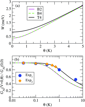 | ||
| Fig. 8 (a) Full width at half maximum of the Kondo peak in the DOS, W, calculated with the model eqn (7); (b) normalized impurity conductance as function of temperature using the function in eqn (10), for the B2, B4 and T4 configurations. The results are compared to experimental data from ref. 16, denoted as “Exp1” and “Exp2”. | ||
| B2 | B4 | T4 | |
|---|---|---|---|
| θ L (K) | 1.91 | 1.96 | 4.09 |
| Δ˜ (meV) | 0.210 | 0.215 | 0.449 |
| z | 0.00315 | 0.00326 | 0.00598 |
| U/πΔ | 5.63 | 5.44 | 5.05 |
Finally, within the approximation considered in this section we also estimate the temperature dependence of the normalized conductance of the Anderson impurity at zero-bias. If one neglects the interference terms (TI ≈ 0), then one can write G(V, θ) ≈ GAI(V, θ) + GB(V, θ), where GB is the background conductance originating from TB, and GAI is the conductance due to TAI + TR,AI. The temperature dependence of GB is usually small, and for small V also the voltage dependence can be neglected, so that we set GB to be a constant background conductance. Within the approximations used in this section, the temperature dependence of GAI is derived in the ESI section S8 (eqn (S29) of the ESI†) to be
 | (9) |
 | (10) |
![[small theta, Greek, tilde]](https://www.rsc.org/images/entities/i_char_e123.gif) K = (21/s − 1)−1/2θK, and θK and s are phenomenological parameters. The value of θK sets the temperature at which the conductance is reduced by a factor 2 (GAI(0, θK) = GAI(0, 0)/2). The second order expansion of this relation leads to
K = (21/s − 1)−1/2θK, and θK and s are phenomenological parameters. The value of θK sets the temperature at which the conductance is reduced by a factor 2 (GAI(0, θK) = GAI(0, 0)/2). The second order expansion of this relation leads to  . As outlined in the ESI section S8,† for the particle-hole symmetric SIAM one can approximate θK ≈ θL. Furthermore, the condition that the second order expansion needs to be equal to the form given in eqn (9) then sets the value of s to be s ≈ 0.20.
A comparison of the temperature dependent conductance obtained using eqn (10) for the B2, B4 and T4 structures with the experimental data in ref. 16 is plotted in Fig. 8(b). The experimental normalized conductance agrees rather well with the calculated curves, in particular with the one for T4, which has the highest Kondo temperature of all the calculated structures. We denote as “Exp1” and “Exp2” the data for the two sets of experiments presented in Fig. 3c and d of ref. 16, respectively. When extracting the experimental Anderson Impurity conductance one has to first subtract the background conductance, GB. Our calculations show that the background conductance depends significantly on the detailed atomic structure, as shown by the values of TB in Fig. 7. However, in experiments only the total conductance is accessible. One can approximate the background conductance by the conductance at zero bias for a very large applied magnetic field, which can be extracted from Fig. 3g–h of ref. 16. In this way we extract the ratio of background conductance to the total conductance at zero bias and zero temperature to be about 0.29 for Exp1, and 0.34 for Exp2.
While the results presented in this section show good agreement with the experiments in ref. 16, the limitation is that the equations are all based on the assumption of a particle-hole symmetric system, which is not generally the case. Indeed, in ref. 16 it is also shown that by applying a gate voltage the occupation of the SIAM can be systematically changed. At particle-hole symmetry the system is characterized by a single energy scale, kBθL, and eqn (7)–(10) reflect this property. Away from particle-hole symmetry, however, this no longer holds and corrections to these formulas enter. Furthermore, the condition that ΓL is very different from ΓR does not apply for a general system. In the next section we will therefore extend the method to the general non-equilibrium case, and also to the case away from particle-hole symmetry within a perturbative approach.
5. Non-equilibrium relations: renormalized super-perturbation theory
In this section we account for finite-temperature (θ > 0) and general finite-bias (V ≠ 0) effects by using the renormalized super perturbation theory (rSPT) described in ref. 22, 23 and 60. The rSPT corresponds to a perturbative method organized around the particle-hole symmetric strong coupling fixed point considered in the previous sections. While for the PTM/Au system considered here we always have U ≫ Δ, the rSPT relations are in principle valid for arbitrary values of U, and account for deviations from the particle-hole symmetry at a perturbative level. It is based on the insight that at the strong-coupling fixed point the equations have the form of an Anderson model, albeit with renormalized parameters.56 These parameters are the renormalized hybridization, Δ˜, which has been introduced in the previous section (Δ˜ = zΔ), the renormalized energy level,![[small epsilon, Greek, tilde]](https://www.rsc.org/images/entities/i_char_e0de.gif) d, which is given by
d, which is given by ![[small epsilon, Greek, tilde]](https://www.rsc.org/images/entities/i_char_e0de.gif) d = (εd + U/2)/Δ, and the renormalized interaction energy, Ũ, defined in the ESI section S9.† We introduce the rescaled renormalized interaction ũ = Ũ/πΔ˜, which lies in the range from 0 for small U to 1 for very large U (see Fig. S9†). In this section we present results as function of
d = (εd + U/2)/Δ, and the renormalized interaction energy, Ũ, defined in the ESI section S9.† We introduce the rescaled renormalized interaction ũ = Ũ/πΔ˜, which lies in the range from 0 for small U to 1 for very large U (see Fig. S9†). In this section we present results as function of ![[small epsilon, Greek, tilde]](https://www.rsc.org/images/entities/i_char_e0de.gif) d, which determines the deviation from the particle-hole symmetric case, and which can be tuned experimentally by applying a gate voltage.16
d, which determines the deviation from the particle-hole symmetric case, and which can be tuned experimentally by applying a gate voltage.16
The Kondo temperature θL near the strong coupling fixed point is obtained as  ,60 with the θ = 0 limit of the static spin susceptibility56
 | (11) |
![[small epsilon, Greek, tilde]](https://www.rsc.org/images/entities/i_char_e0de.gif) d we have
d we haveÃAI(0, 0) ≈ [πΔ˜(1 + (1 − ũ)2![[small epsilon, Greek, tilde]](https://www.rsc.org/images/entities/i_char_e0de.gif) d2)]−1. d2)]−1. | (12) |
Inserting this into eqn (11) yields the Kondo temperature
 | (13) |
![[small epsilon, Greek, tilde]](https://www.rsc.org/images/entities/i_char_e0de.gif) d and to arbitrary U of the result for the symmetric SIAM in the strong coupling limit given in eqn (8).
d and to arbitrary U of the result for the symmetric SIAM in the strong coupling limit given in eqn (8).
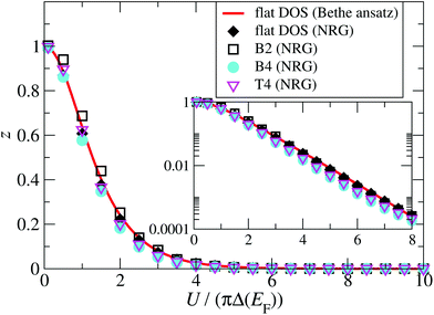
A central issue is the relation between renormalized and bare parameters, which is encoded in the wave-function renormalization factor z. The renormalization factor z = Δ˜/Δ can be obtained from NRG for a general energy-dependent hybridization function, and from Bethe ansatz for the case of a constant energy-independent hybridization function.56 A comparison between z calculated for a constant hybridization function Δ(E) = Δ(EF) = Γ/2 using Bethe ansatz and the NRG is shown as function of the interaction energy in Fig. 9, and demonstrates that they agree well. To address the question of the effect of an energy-dependent hybridization function on z, we also calculate z using NRG and with the full energy-dependent Δ(E) for the B2, B4, and T4 structures (Fig. 5). Importantly, we find that they also agree rather well with the results for constant hybridization, showing that the low energy SIAM is largely dominated by the hybridization function around the Fermi energy. Based on these results we therefore calculate z and ũ for the rSPT expansion using the Bethe ansatz for the particle-hole symmetric SIAM with constant hybridization Δ(EF) = Γ/2 (see Fig. S9 in the ESI section S9†), where the values of Γ for each configuration are given in Fig. 2.
In order to generalize the relations for the conductance, we first evaluate the equilibrium conductance, G0 = GAI(V = 0, θ = 0, B = 0), defined in eqn (6) and (S18) of the ESI,† away from the particle-hole symmetry. Here we have explicitly noted that we consider the reference case with zero magnetic field (B). This results to
 | (14) |
Then the extension of rSPT to current-carrying steady states allows us to evaluate the non-linear low-voltage conductance for finite temperatures and also magnetic fields, which has the form:22,23,60
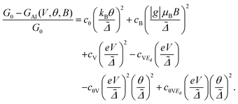 | (15) |
This result can be obtained by expanding GAI(θ, V, B) up to second order in eV/Δ˜, kBθ/Δ˜, and gμBB/Δ˜. The relations for the expansion coefficients are presented in the ESI section S9,† and extend the second order coefficients in U given in ref. 22 to arbitrarily large values of U. Note that the equilibrium transmission calculations, presented in the previous section and in the ESI section S8,† allow to extract the values of cθ = π2 and also cV = 3/2 in the strong coupling limit (ũ = 1) and at particle-hole symmetry (ε˜d = 0), and for highly asymmetric coupling to the electrodes (eqn (S29) in the ESI†). Using the general rSPT relations given in the ESI section S9† one can see that as long as ũ = 1 and ε˜d = 0 these values are valid for arbitrary ΓL and ΓR, so that they are independent of the level of asymmetry in the electronic coupling to the electrodes. Note that an important advantage of the rSPT approach is that it is not restricted to these limiting cases, and it is valid for arbitrary values of the parameters, which is a consequence of the fact that it is a truly non-equilibrium method.
The rSPT expansion coefficients calculated for the B2, B4, and T4 structures are displayed in Fig. 10 as a function of the local level energy ![[small epsilon, Greek, tilde]](https://www.rsc.org/images/entities/i_char_e0de.gif) d = (εd + U/2)/Δ. As noted above, in an experiment this can be modified by applying a gate voltage. We use the Bethe ansatz ε˜d = 0 for the values of U/πΔ give in Table 1, which then result to ũ = 0.99999418 for the B2 structure, ũ = 0.99999088 for B4, and ũ = 0.99997705 for T4. These values are all very close to 1, and indeed replacing them with 1 leads to essentially the same results, confirming that the Au-PTM system is in the strong coupling limit. The coefficients therefore differ only due to the changes in ΓL/ΓR, for which we use the DFT values given in Fig. 2. Since cθ and cB are linear-response properties and do not depend on ΓL/ΓR, they are identical for all configurations. Consequently, cθ and cB can also be calculated via NRG. A comparison for these two quantities between rSPT and NRG is given in ref. 23, where a rather good agreement is found up to moderate values of
d = (εd + U/2)/Δ. As noted above, in an experiment this can be modified by applying a gate voltage. We use the Bethe ansatz ε˜d = 0 for the values of U/πΔ give in Table 1, which then result to ũ = 0.99999418 for the B2 structure, ũ = 0.99999088 for B4, and ũ = 0.99997705 for T4. These values are all very close to 1, and indeed replacing them with 1 leads to essentially the same results, confirming that the Au-PTM system is in the strong coupling limit. The coefficients therefore differ only due to the changes in ΓL/ΓR, for which we use the DFT values given in Fig. 2. Since cθ and cB are linear-response properties and do not depend on ΓL/ΓR, they are identical for all configurations. Consequently, cθ and cB can also be calculated via NRG. A comparison for these two quantities between rSPT and NRG is given in ref. 23, where a rather good agreement is found up to moderate values of ![[small epsilon, Greek, tilde]](https://www.rsc.org/images/entities/i_char_e0de.gif) d.
d.
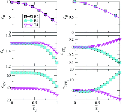 | ||
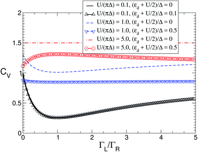
Fig. 10 The dependence of the conductance coefficients in eqn (15) on the deviation from particle-hole symmetry, determined by ![[small epsilon, Greek, tilde]](https://www.rsc.org/images/entities/i_char_e0de.gif) d = (εd + U/2)/Δ(EF), for the configurations B2, B4 and T4. The mathematical relations for the coefficients are given in the ESI section S9,† and the parameter ζ = 3(ΓL/ΓR)/(1 + ΓL/ΓR)2 in those equations, which determines the asymmetry of the electronic coupling to the left and right electrodes, follows from the values of ΓR and ΓL in Fig. 2 as ζB2 = 2.6 × 10⁻⁴, ζB4 = 2.6 × 10⁻⁴, and ζT4 = 0.568. The dimensionless Coulomb repulsion U/(πΔ(EF)) for the effective Anderson model applicable to each system is presented in Table 1. d = (εd + U/2)/Δ(EF), for the configurations B2, B4 and T4. The mathematical relations for the coefficients are given in the ESI section S9,† and the parameter ζ = 3(ΓL/ΓR)/(1 + ΓL/ΓR)2 in those equations, which determines the asymmetry of the electronic coupling to the left and right electrodes, follows from the values of ΓR and ΓL in Fig. 2 as ζB2 = 2.6 × 10⁻⁴, ζB4 = 2.6 × 10⁻⁴, and ζT4 = 0.568. The dimensionless Coulomb repulsion U/(πΔ(EF)) for the effective Anderson model applicable to each system is presented in Table 1. | ||
The effect of the contact asymmetry, as captured by the ratio ΓL/ΓR, affects the value of the finite voltage coefficients, as clearly seen in the lower part of Fig. 10. At particle hole symmetry (ε˜d = 0) the influence of the contact asymmetry vanishes, except for cθV. A more detailed analysis of this effect is presented in Fig. 11, where we show cV as function of ΓL/ΓR for different value of ![[small epsilon, Greek, tilde]](https://www.rsc.org/images/entities/i_char_e0de.gif) d and U. It can be seen that the overall variations of cV are rather large, and only as the system goes into the strongly interacting regime (large U) the effect of contact asymmetry becomes small, and it completely vanishes for very large U and ε˜d = 0, where it reaches the limiting value of 3/2 discussed above. Note that around ΓL/ΓR = 1 (symmetric coupling) cV varies quadratically for small variations of ΓL/ΓR around 1 (see also ESI section S9†).
d and U. It can be seen that the overall variations of cV are rather large, and only as the system goes into the strongly interacting regime (large U) the effect of contact asymmetry becomes small, and it completely vanishes for very large U and ε˜d = 0, where it reaches the limiting value of 3/2 discussed above. Note that around ΓL/ΓR = 1 (symmetric coupling) cV varies quadratically for small variations of ΓL/ΓR around 1 (see also ESI section S9†).
The rSPT provides a consistent description of the low-temperature, low-field, low-bias transport properties of the Anderson model. When the parameters are calculated from DFT + NEGF, and combined with NRG and/or Bethe ansatz, the method allows for an effectively first principles calculation of all the transport parameters. If the atomic structure is well defined, as is the case in STM experiment of molecules or other adsorbates on flat surfaces,24 the approach is predictive on a quantitative level. When the structure is not known, as is the case for the PTM/Au system considered here, the approach allows to estimate ranges of possible electronic coupling coefficients, interactions energies and deviations from the particle-hole asymmetry. In this case the results give a qualitative guidance to experiments as to which atomic structures are expected to lead to Kondo physics in a measurement.
6. Conclusions
The theoretical modeling of Kondo physics in nanoscale devices is usually limited to fitting the parameters of a SIAM to conductivity measurements. Due to this adjustment of the parameters to the experiment such an approach is therefore not predictive, and the question whether it captures the right physics for a given experiment is therefore open. Moreover, it does not provide any information on the relationship between the device structure and its conductance as well as its electronic interactions. In order to overcome this limitation and provide a predictive model here we present a scheme that obtains the required parameters of the SIAM from DFT calculations for realistic atomic structures. Importantly, conductance measurements are inherently a non-equilibrium process, and our novel scheme combining DFT, NEGF, NRG and rSPT is designed to capture such effects. We derive the equations that relate the equilibrium density of states to the non-equilibrium conductance versus voltage curves, which is necessary to interpret experimental conductance measurements in terms of the electronic and atomic structure of the system. With this approach it is therefore possible to calculate the electronic and non-equilibrium transport properties of strongly correlated molecular junctions in a systematic and predictive way effectively from first principles.We employ the method for the description of the recently measured Au/PTM/Au break-junctions. The main limitation of break-junction experiments is that the statistical nature of the measurements does not allow a direct understanding of the atomic structures responsible for the conductance and its variations. First-principles calculations are therefore essential to gain a full atomistic insight on the system properties. While state of the art DFT + NEGF can only be applied to weakly correlated systems, the method presented here is proven to overcome this limitation. In fact, for the Au/PTM/Au break-junction we show how the molecule–electrode contacts affect the energy level alignment, charge transfer, hybridization and, ultimately, the Kondo temperature and conductance. Importantly, we show that while the Kondo temperature depends only on the total hybridization of the molecules with the electrodes, the experimental conductance depends also on the relative coupling to left and right electrodes, since those determine the current flow. Our projection scheme allows us to obtain these required individual electronic couplings from DFT, and with these we are able to evaluate the low bias conductance versus voltage curves by means of the rSPT. For PTM molecules weakly coupled to the electrodes, as is the case for a molecule on an idealized perfectly flat Au surface, we predict the Kondo temperature to lie below the experimentally accessible limit. In contrast, for asymmetric junctions with molecules on a corrugated Au surface, where the central carbon atom has a good electronic contact with the Au, the calculated Kondo temperature is in good agreement with experiments. These results are consistent with the experimental finding, where only a limited number of junctions exhibit Kondo features in the conductance at the accessible low temperatures.
Finally, we note that for experimental setups, where the atomic structure is well characterized, such as for certain adsorbates or defects on flat metal surfaces, the method will enable quantitative comparisons with low-noise experiments. By eliminating free parameters it can therefore lead to a systematic understanding of the non-equilibrium Kondo physics of molecular systems. The inclusion of the rSPT allows to predict systematic changes in non-linear transport at low voltage, temperature and magnetic field, which cannot be addressed directly from state of the art calculations of the transmission coefficient alone. Such changes can be induced experimentally, for example by varying the scanning tip height, which modifies the asymmetry in the electronic coupling to the electrodes, and these can then be calculated effectively from first principles with the approach presented here. Our method therefore paves the way toward the rational design of Kondo systems, and the possibility of performing systematic comparisons with unprecedented accuracy between theory and experiments.
Conflicts of interest
There are no conflicts to declare.Acknowledgements
A. D. and I. R. would like to thank E. Burzurí and A. V. Rudnev for useful discussions about transport experiments in Au/PTM/Au junctions, and C. Weber for insightful discussions on the Kondo physics. A. D. and I. R. acknowledge the financial support from the EU project ACMOL (FET Young Explorers, No. 618082). A. D. received additional support from EU Marie Sklodowska-Curie project SPINMAN (No. SEP-210189940) and from the Ministerio de Economía y Competitividad de España (No. FPDI-2013-16641). I. R. acknowledges additional financial support from the EU H2020 programme PETMEM project (Grant No. 688282). I. R. thanks the Cambridge CSD3 HPC centre for providing part of the computing resources. W. H. A., L. C. and D. V. acknowledge the financial support from the Deutsche Forschungsgemeinschaft through TRR80/F6, TRR80/G7 and the FOR1346/P3. E. Muñoz acknowledges financial support by Fondecyt (Chile) No. 1141146. M. M. Radonjić acknowledges the support from Ministry of Education, Science, and Technological Development of the Republic of Serbia under project ON171017. S. Kirchner acknowledges support by the National Key R&D Program of the MOST of China, grant No. 2016YFA0300202, the National Science Foundation of China, grant No. 11774307 and No. 11474250, and the U.S. Army RDECOM – Atlantic Grant No. W911NF-17-1-0108.References
- S. V. Aradhya and L. Venkataraman, Nat. Nanotechnol., 2013, 8, 399 CrossRef PubMed.
- L. Bogani and W. Wernsdorfer, Nat. Mater., 2008, 7, 179 CrossRef PubMed.
- D. Xiang, X. Wang, C. Jia, T. Lee and X. Guo, Chem. Rev., 2016, 116, 4318 CrossRef PubMed.
- W. Kohn, Rev. Mod. Phys., 1999, 71, 1253 CrossRef.
- J. Taylor, H. Guo and J. Wang, Phys. Rev. B: Condens. Matter Mater. Phys., 2001, 63, 245407 CrossRef.
- M. Brandbyge, J.-L. Mozos, P. Ordejón, J. Taylor and K. Stokbro, Phys. Rev. B: Condens. Matter Mater. Phys., 2002, 65, 165401 CrossRef.
- A. R. Rocha, V. M. García-Suárez, S. Bailey, C. Lambert, J. Ferrer and S. Sanvito, Phys. Rev. B: Condens. Matter Mater. Phys., 2006, 73, 085414 CrossRef.
- J. J. Palacios, A. J. Pérez-Jiménez, E. Louis, E. SanFabián and J. A. Vergés, Phys. Rev. B: Condens. Matter Mater. Phys., 2002, 66, 035322 CrossRef.
- A. Pecchia and A. di Carlo, Rep. Prog. Phys., 2004, 67, 1497 CrossRef.
- G. Stefanucci and S. Kurth, Phys. Rev. Lett., 2011, 107, 216401 CrossRef PubMed.
- P. Tröster, P. Schmitteckert and F. Evers, Phys. Rev. B: Condens. Matter Mater. Phys., 2012, 85, 115409 CrossRef.
- J. P. Bergfield, Z.-F. Liu, K. Burke and C. A. Stafford, Phys. Rev. Lett., 2012, 108, 066801 CrossRef PubMed.
- G. Stefanucci and S. Kurth, Nano Lett., 2015, 15, 8020–8025 CrossRef PubMed.
- S. Kurth and G. Stefanucci, Phys. Rev. B: Condens. Matter Mater. Phys., 2016, 94, 241103 CrossRef.
- D. Jacob and S. Kurth, Nano Lett., 2018, 18, 2086–2090 CrossRef PubMed.
- R. Frisenda, R. Gaudenzi, C. Franco, M. Mas-Torrent, C. Rovira, J. Veciana, I. Alcon, S. T. Bromley, E. Burzurí and H. S. Van der Zant, Nano Lett., 2015, 15, 3109–3114 CrossRef PubMed.
- S. Datta, Electronic Transport in Mesoscopic Systems, Cambridge University Press, Cambridge, UK, 1995 Search PubMed.
- K. G. Wilson, Rev. Mod. Phys., 1975, 47, 773–840 CrossRef.
- H. R. Krishna-murthy, J. W. Wilkins and K. G. Wilson, Phys. Rev. B: Condens. Matter Mater. Phys., 1980, 21, 1003–1043 CrossRef.
- H. R. Krishna-murthy, J. W. Wilkins and K. G. Wilson, Phys. Rev. B: Condens. Matter Mater. Phys., 1980, 21, 1044–1083 CrossRef.
- R. Bulla, T. A. Costi and T. Pruschke, Rev. Mod. Phys., 2008, 80, 395–450 CrossRef.
- E. Muñoz, C. J. Bolech and S. Kirchner, Phys. Rev. Lett., 2013, 110, 016601 CrossRef PubMed.
- E. Muñoz, F. Zamani, L. Merker, T. A. Costi and S. Kirchner, J. Phys.: Conf. Ser., 2017, 807, 092001 CrossRef.
- A. Droghetti and I. Rungger, Phys. Rev. B: Condens. Matter Mater. Phys., 2017, 95, 085131 CrossRef.
- D. Jacob, K. Haule and G. Kotliar, Phys. Rev. Lett., 2009, 103, 016803 CrossRef PubMed.
- D. Jacob, K. Haule and G. Kotliar, Phys. Rev. B: Condens. Matter Mater. Phys., 2010, 82, 195115 CrossRef.
- M. Karolak, D. Jacob and A. I. Lichtenstein, Phys. Rev. Lett., 2011, 107, 146604 CrossRef PubMed.
- D. Jacob, M. Soriano and J. J. Palacios, Phys. Rev. B: Condens. Matter Mater. Phys., 2013, 88, 134417 CrossRef.
- D. Jacob, J. Phys.: Condens. Matter, 2015, 27, 245606 CrossRef PubMed.
- L. Chioncel, C. Morari, A. Östlin, W. H. Appelt, A. Droghetti, M. M. Radonjić, I. Rungger, L. Vitos, U. Eckern and A. V. Postnikov, Phys. Rev. B: Condens. Matter Mater. Phys., 2015, 92, 054431 CrossRef.
- R. Requist, S. Modesti, P. P. Baruselli, A. Smogunov, M. Fabrizio and E. Tosatti, Proc. Natl. Acad. Sci. U. S. A., 2014, 111, 69 CrossRef PubMed.
- P. Lucignano, R. Mazzarello, A. Smogunov, M. Fabrizio and E. Tosatti, Nat. Mater., 2009, 8, 563 CrossRef PubMed.
- P. P. Baruselli, A. Smogunov, M. Fabrizio and E. Tosatti, Phys. Rev. Lett., 2012, 108, 206807 CrossRef PubMed.
- J. Liu, H. Isshiki, K. Katoh, T. Morita, B. K. Breedlove, M. Yamashita and T. Komeda, J. Am. Chem. Soc., 2013, 135, 651 CrossRef PubMed.
- Y.-h. Zhang, S. Kahle, T. Herden, C. Stroh, M. Mayor, U. Schlickum, M. Ternes, P. Wahl and K. Kern, Nat. Commun., 2013, 4, 2110 CrossRef PubMed.
- F. Bejarano, I. J. Olavarria-Contreras, A. Droghetti, I. Rungger, A. Rudnev, D. Gutiérrez, M. Mas-Torrent, J. Veciana, H. S. J. van der Zant, C. Rovira, E. Burzurí and N. Crivillers, J. Am. Chem. Soc., 2018, 140, 1691–1696 CrossRef PubMed.
- W. R. French, C. R. Iacovella, I. Rungger, A. M. Souza, S. Sanvito and P. T. Cummings, Nanoscale, 2013, 5, 3654 RSC.
- W. R. French, C. R. Iacovella, I. Rungger, A. M. Souza, S. Sanvito and P. T. Cummings, J. Phys. Chem. Lett., 2013, 4, 887 CrossRef PubMed.
- N. Crivillers, C. Munuera, M. Mas-Torrent, C. Simao, S. T. Bromley, C. Ocal, C. Rovira and J. Veciana, Adv. Mater., 2009, 21, 1177 CrossRef.
- N. Crivillers, M. Paradinas, M. Mas-Torrent, S. T. Bromley, C. Rovira, C. Ocal and J. Veciana, Chem. Commun., 2011, 47, 4664 RSC.
- G. Seber, A. V. Rudnev, A. Droghetti, I. Rungger, J. Veciana, M. Mas-Torrent, C. Rovira and N. Crivillers, Chem. – Eur. J., 2017, 23, 1415 CrossRef PubMed.
- A. Droghetti, I. Rungger, C. Das Pemmaraju and S. Sanvito, Phys. Rev. B: Condens. Matter Mater. Phys., 2016, 93, 195208 CrossRef.
- P. W. Anderson, Phys. Rev., 1961, 124, 41–53 CrossRef.
- G. Kotliar, S. Y. Savrasov, K. Haule, V. S. Oudovenko, O. Parcollet and C. A. Marianetti, Rev. Mod. Phys., 2006, 78, 865–951 CrossRef.
- A. G. Petukhov, I. I. Mazin, L. Chioncel and A. I. Lichtenstein, Phys. Rev. B: Condens. Matter Mater. Phys., 2003, 67, 153106 CrossRef.
- M. I. Katsnelson, V. Y. Irkhin, L. Chioncel, A. I. Lichtenstein and R. A. de Groot, Rev. Mod. Phys., 2008, 80(315), 315–378 CrossRef.
- P. Huang and E. A. Carter, Nano Lett., 2006, 6, 1146 CrossRef PubMed.
- F. Libisch, C. Huang and E. A. Carter, Acc. Chem. Res., 2014, 47, 2768 CrossRef PubMed.
- Q. Sun and G. K.-L. Chan, Acc. Chem. Res., 2705, 49, 2705 CrossRef PubMed.
- J. Schrieffer and P. Wolff, Phys. Rev., 1966, 149, 491 CrossRef.
- A. Hewson, The Kondo Problem to Heavy Fermions, Cambridge Univ. Press, Cambridge, UK, 1993 Search PubMed.
- F. D. M. Haldane, J. Phys. C: Solid State Phys., 1978, 11, 5015 CrossRef.
- B. Himmetoglu, A. Floris, S. de Gironcoli and M. Cococcioni, Int. J. Quantum Chem., 2014, 114, 14 CrossRef.
- A. M. Souza, I. Rungger, C. D. Pemmaraju, U. Schwingenschlögl and S. Sanvito, Phys. Rev. B: Condens. Matter Mater. Phys., 2013, 88, 165112 CrossRef.
- A. M. Souza, I. Rungger, R. B. Pontes, A. R. Rocha, A. J. Roque da Silva, U. Schwingenschlögl and S. Sanvito, Nanoscale, 2014, 6, 14495 RSC.
- A. C. Hewson, Phys. Rev. Lett., 1993, 70, 4007 CrossRef PubMed.
- K. Nagaoka, T. Jamneala, M. Grobis and M. F. Crommie, Phys. Rev. Lett., 2002, 88, 077205 CrossRef PubMed.
- D. Goldhaber-Gordon, J. Gores, M. A. Kastner, H. Shtrikman, D. Mahalu and U. Meirav, Phys. Rev. Lett., 1998, 81, 5225 CrossRef.
- T. A. Costi, A. C. Hewson and V. Zlatić, J. Phys.: Condens. Matter, 1994, 6, 2519 CrossRef.
- L. Merker, S. Kirchner, E. Muñoz and T. A. Costi, Phys. Rev. B: Condens. Matter Mater. Phys., 2013, 87, 165132 CrossRef.
Footnotes |
| † Electronic supplementary information (ESI) available: DETAILS. See DOI: 10.1039/C8NR03991G |
| ‡ These authors contributed equally to this work. |
| This journal is © The Royal Society of Chemistry 2018 |

