
 Open Access Article
 This Open Access Article is licensed under a Creative Commons Attribution-Non Commercial 3.0 Unported Licence
How the crystal structure and phase segregation of Au–Fe alloy nanoparticles are ruled by the molar fraction and size†
Anna
Tymoczko
a,
Marius
Kamp
b,
Oleg
Prymak
c,
Christoph
Rehbock
a,
Jurij
Jakobi
a,
Ulrich
Schürmann
b,
Lorenz
Kienle
b and
Stephan
Barcikowski
 *a
*a
aTechnical Chemistry I and Center for Nanointegration Duisburg-Essen (CENIDE), University Duisburg-Essen, Universitätstr. 7, 45141 Essen, Germany
bFaculty of Engineering CAU Kiel, Institute for Materials Science, Synthesis and Real Structure, Kaiserstraße 2, 24143 Kiel, Germany
cDepartment of Inorganic Chemistry, University Duisburg-Essen, Universitätstr. 7, 45141 Essen, Germany. E-mail: stephan.barcikowski@uni-due.de
First published on 23rd August 2018
Abstract
The application of an Au–Fe nanoalloy is determined by its internal phase structure. Our experimental and theoretical findings explain how the prevalence of either a core–shell or a disordered solid solution structure is ruled by the target composition and the particle diameter. Furthermore, we found metastable phases not predefined by the bulk phase diagram.
Au–Fe nanomaterials with a defined internal structure1 are beneficial for numerous possible applications,2e.g. for electrocatalytic oxygen evolution3 or during MRI/optical dual imaging.4 Furthermore, the Au–Fe nano-system is highly interesting from a fundamental point of view due to extended miscibility gaps and deviating crystal structures of its constituents in the bulk (Au-face centered cubic (FCC) vs. Fe-body-centered cubic (BCC)).5 To date it is basically unknown to what extent the internal phase and crystal structure of Au–Fe nanoparticles (NPs) can be correlated with the particle size and composition, though significant differences in comparison with the bulk can be expected based on theoretical calculations.1 The as-defined solid solutions or segregated Au–Fe NPs are very tedious to produce using chemical co-precipitation and reversed micelle methods.6 Laser ablation in liquid (LAL)7 is a viable alternative, producing ligand free nanoparticles on a gram scale.8 To date some research in the area of laser-generated gold rich Au–Fe alloy NPs has been conducted aiming at control over optical and magnetic properties in correlation with the composition and the surrounding media. Metastable alloys with different mixing grades9 were synthesized, with clear dependency on the molar ratio10 and surrounding liquids.11 Even though the Au–Fe system has been subjected to a number of experimental investigations a deeper understanding of the complex formation mechanism in correlation with the target composition and the particle diameter is still lacking particularly for iron-rich systems where segregated structures are anticipated based on the bulk phase diagram.
Herein we report that in Au–Fe NPs formed by LAL the emergence of a core shell (CS) structure is favored for NPs with a diameter exceeding 10 nm, Fe molar fractions in the target >35% and deviating crystal structures (Au-face centered cubic (FCC) & Fe-body-centered cubic (BCC)). On the other hand, disordered solid solution (SS) nanoparticles with the Fe-FCC structure and number mean diameters <10 nm always form independent of the Fe content. Au–Fe NPs were synthesized using LAL in acetone (see the ESI for details†) from bulk targets with varied Fe![[thin space (1/6-em)]](https://www.rsc.org/images/entities/char_2009.gif) :Au ratios. High resolution imaging by scanning transmission electron microscopy (TEM) in combination with energy-dispersive X-ray spectroscopy (EDX) line scans revealed the formation of two internal phase structures, a disordered solid solution and a FeAu@AuFe core–shell structure clearly distinguishable by the presence/absence of a defined phase boundary detected in TEM and EDX (Fig. 1 and S1†). In consecutive experiments we aimed at elucidating to what extent the emergence of these structures was correlated with the target composition, the particle diameter and the overall crystal structure determined by X-ray powder diffraction (XRD).
:Au ratios. High resolution imaging by scanning transmission electron microscopy (TEM) in combination with energy-dispersive X-ray spectroscopy (EDX) line scans revealed the formation of two internal phase structures, a disordered solid solution and a FeAu@AuFe core–shell structure clearly distinguishable by the presence/absence of a defined phase boundary detected in TEM and EDX (Fig. 1 and S1†). In consecutive experiments we aimed at elucidating to what extent the emergence of these structures was correlated with the target composition, the particle diameter and the overall crystal structure determined by X-ray powder diffraction (XRD).
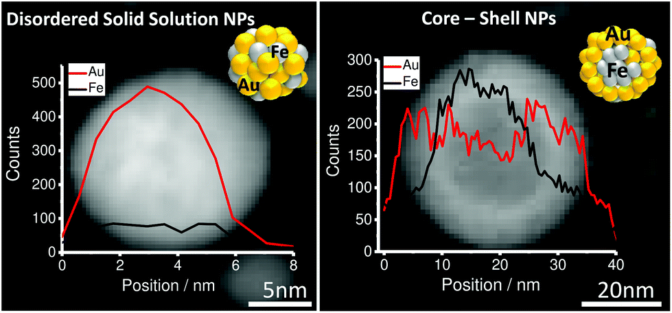 | ||
| Fig. 1 EDX composition analysis for Au–Fe LAL generated NPs in acetone (disordered solid solution SS [left] and core–shell CS [right]). | ||
Notably, for iron rich NPs (Fe > 35%), 2 fractions of NPs with number mean diameters > and <10 nm were detected (Fig. 2a and S2†). Bimodal size distributions were expected as previously shown, based on different ablation mechanisms.8 In contrast, from Au rich targets (Fe < 35%) monomodal particle size distributions with number mean diameters <10 nm were generated. In this context it should be noted that when discussing number mean diameters, derived from fitting particle size distributions with a log-normal function, the presence of low fractions of particles >10 nm cannot be excluded in these samples. The overall reduced abundance of larger particles in gold-rich alloy NPs may be explained by size quenching caused by specific solvent–surface interactions between gold-rich surfaces and acetone.12
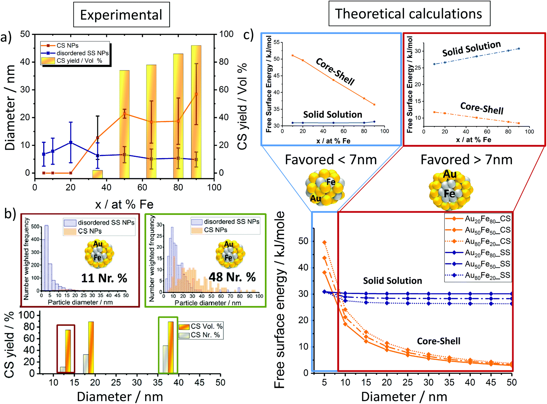 | ||
| Fig. 2 Factors determining the disordered solid solution versus the core–shell NP yield; (a) nanoparticle size-target composition dependency (disordered SS & CS NPs) for Au–Fe NPs generated via LAL in acetone. (b) Influence on the CS yield% based on the average size of Au–Fe NPs for both volume (vol%) and number ratio (Nr%). (c) Theoretical calculations are based on the Chattopaghyay model.13 | ||
Based on this we deduced a clear particle diameter/Fe%-structure dependency. Our analysis revealed that all particles with number mean diameters <10 nm had a disordered solid solution structure, while the core–shell was only found for NPs >10 nm. This trend was quantified by determining the volume-weighted CS NPs yield (Fig. 2a). It may be concluded that phase segregation (CS-formation) is only observed for NPs with diameters >10 nm and Fe molar fractions >35%. Additionally, disordered SS forms independent of the target composition.
Thermodynamic calculations, described in more detail elsewhere by Chattopadhyay et al.,13 were employed to predict how the most favored ultrastructure (SS or CS NPs) depends on the particle diameter (Fig. 2c). In this model surface free energies for CS and SS morphologies at the predefined diameter and composition are calculated, indicating the thermodynamically most stable structure by minimum Gibbs energy, confirmed by Wulff construction.14 Even though a slight dependency of the free energy on the composition was observed, the impact of the particle diameter was much more pronounced. The results clearly show that NPs with diameters <7 nm would be thermodynamically more stable as SS NPs independent of the Fe molar ratio. In the case of NPs with diameters >7 nm, phase segregation and hence the emergence of CS NPs should be preferred (Fig. 2c). These calculations confirm our experimental findings, showing CS structures only for mean particle diameters >10 nm (Fig. 2a). The correlation between the diameter and CS yield was further verified by investigation of two laser-generated colloids with deviating diameter distributions but identical target compositions (Au50Fe50) (Fig. 2b). The results are fully consistent with our expectations, the number of generated CS increases with increasing NP size. Even though the CS yield increased with increasing Fe molar fraction and diameter, the disordered SS alloy NPs are always present independent of the target composition. This is surprising as in accordance with the Hume-Rothery rule,15 miscibility of Au and Fe defines the system as mostly immiscible (bulk solubility at room temperature: 3% Au in Fe and 0.3% Au in Fe)5 because of the differences in the lattice parameters (AuFCC 4.076 Å; FeBCC 2.866 Å) and in the surface energies (Au 1.5 J m−2; Fe 2.4 J m−2).16,17 Based on this, the segregated phase (CS) should be the only thermodynamically stable phase. To examine this phenomenon in more detail, we determined the crystal structure of the generated Au–Fe NPs by X-ray powder diffraction (XRD) including Rietveld refinement and the calculation of lattice parameters for FCC and BCC phases (Fig. 3 and Fig. S3†). The analysis revealed that for target compositions >65% a BCC iron phase was dominant in the NPs, which basically coincides with the occurrence of CS phase structures in transmission electron microscopy. In this context it should be noted that the lattice constants of this phase are slightly elevated compared to bulk Fe, which points at partial substitution of iron with Au within the particle's core. In addition, a Au–Fe FCC structure is detectable over the whole composition range, which can be clearly attributed to the disordered SS NPs in gold rich samples. In iron rich samples, however, disordered SS NPs and gold rich shells cannot be differentiated based on XRD. This Au-FCC phase exhibits a reduction in lattice parameters from 4.1 to 3.95 Å while increasing the iron molar fraction up to 65%, which evidences alloy formation and substitutions by iron atoms in the FCC-Au lattice. As the substitutions are significantly higher than those predicted by the bulk phase diagram (Fig. 4), the formation of a metastable phase is verified. For iron contents >65%, the substitution by Fe within the FCC-Au lattice decreases due to competition between the BCC/FCC phase as predicted by Baricco.18 In general, the FCC Au–Fe phase exhibits the strongest negative deviations from Vegard's law at a composition around 50:50. Similar observations were also made in Ag–Au nanoparticles produced by the same method.19 Finally, the mass fractions of FCC/BCC were calculated from the Rietveld refined peaks (Fig. 3). Here we can clearly observe that an increase in the BCC fraction also goes along with a more pronounced CS formation (compare Fig. 2a). These data show that next to the size restrictions, the NP crystal structure correlates with the phase segregation. However, one peculiarity was found for the Au50Fe50 as well as to a smaller extent for the Au65Fe35 composition. Here we clearly verified the formation of CS structures by TEM, while on the other hand no BCC-iron was found. These findings may indicate that CS structures may also form based on two FCC alloy structures (gold-rich Au–Fe shell around the iron-rich Fe–Au core) with distinguishable compositions. Here AuFe@AuFe is probably formed. The presence of up to three distinguishable FCC structures in XRD (FCC 1, FCC 2 and FCC 3 in Fig. 3) seems to point in this direction. In this context the iron-rich FCC (lower lattice parameter, FCC 1 and FCC 2) could come from the core and the gold-rich FCC (higher lattice parameter, FCC 3) could originate from the shell. However, this phenomenon cannot be comprehensively explained based on these data.
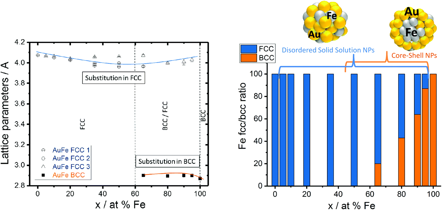 | ||
| Fig. 3 Au–Fe lattice parameters (FCC 1, FCC 2, and FCC 3 represent alloy structures with different substitution grades) and weighted phase ratios between BCC/FCC structures measured by XRD. | ||
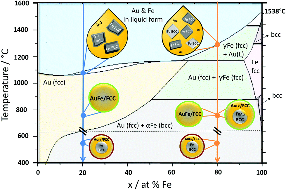 | ||
| Fig. 4 Formation mechanism for Au–Fe nanoparticles generated by LAL. Cool down arrows showing two representative phases, Au20Fe80 (orange line) and Au80Fe20 (blue line). Green circles indicate the metastable product found as a product of our synthesis, while red circles show the product which would be most stable according to the bulk phase diagram but which is NOT synthesized in our process. The Au–Fe phase diagram redrawn from Ref. 14. | ||
As we could clearly verify that the LAL-generated iron-rich Au–Fe NPs are metastable structures with alloy cores and alloy shells, in this final paragraph we aim to elucidate their formation mechanism during LAL based on the bulk Au–Fe phase diagram (Fig. 4). At the first stage both Au and Fe are rapidly cooled down from the liquid state. Gold would stay longer in this state as its melting temperature is lower (Au 1064 °C; Fe 1538 °C).18 Therefore, at the liquidus line interface, solid Fe would be surrounded by liquid Au. In the case of Fe rich systems, e.g. Au20Fe80, Fe can crystallize as either BCC or FCC. Hence both structures will be present upon solidification of the entire phase and will shape the final structure, containing BCC iron rich cores with minimal Au substitution as well as gold rich FCC phases, either as isolated particles or as gold-rich alloy shells. Metastable states, in this case, are indicated by higher substitution of Fe in Au and Au in Fe in contrast to thermodynamically-favored phases at room temperature. On the other hand, for Au rich alloys, e.g. Au80Fe20, only FCC iron can form upon crystallization. As the phase transformation from FCC to BCC may be kinetically hindered due to the fast cooling inherent to the LAL process, and FCC formation may require a lower driving force of formation (as the matrix is also FCC),5 therefore only FCC Au–Fe alloy NPs emerge and no BCC iron is found.
In conclusion, the final internal phase structure (ultrastructure) of Au–Fe NPs generated by LAL in acetone is critically affected by the target composition and the particle diameter. The formation of CS is favored in iron-rich targets (Fe mol% >35), for particles >10 nm and results in BCC iron crystal structures. We could conclusively prove that LAL generates non-equilibrium alloy materials containing FeAu@AuFe core–shell structures where the core and shell are both alloys. This underlines the fundamental significance of this work in understanding the formation of disordered solid solution alloys and segregated nano structures in the Au–Fe system, which may be initial steps towards a nanoscale-phase diagram with particle size as a third axis next to composition. Furthermore, this work may also give access to novel metastable Au–Fe alloy nanomaterials with potential future applicability in catalysis and biomedicine.
Conflicts of interest
The authors declare no conflict of interest.Acknowledgements
We acknowledge financial support from DFG (BA 3580/18-1 and KI 1263/15-1).References
- F. Calvo, Nanoalloys: From Fundamentals to Emergent Applications, Elsevier, 2013 Search PubMed.
- A. H. Lu, E. L. Salabas and F. Schuth, Angew. Chem., Int. Ed. Engl., 2007, 46, 1222–1244 CrossRef PubMed.
- I. Vassalini, L. Borgese, M. Mariz, S. Polizzi, G. Aquilanti, P. Ghigna, A. Sartorel, V. Amendola and I. Alessandri, Angew. Chem., Int. Ed. Engl., 2017, 56, 6589–6593 CrossRef PubMed.
- L. M. Liz-Marzan, Langmuir, 2006, 22, 32–41 CrossRef PubMed.
- D. Favez, J. D. Wagniere and M. Rappaz, Acta Mater., 2010, 58, 1016–1025 CrossRef.
- I. Sharifi, H. Shokrollahi, M. M. Doroodmand and R. Safi, J. Magn. Magn. Mater., 2012, 324, 1854–1861 CrossRef.
- D. Zhang, B. Gokce and S. Barcikowski, Chem. Rev., 2017, 117, 3990–4103 CrossRef PubMed.
- R. Streubel, S. Barcikowski and B. Gokce, Opt. Lett., 2016, 41, 1486–1489 CrossRef PubMed.
- V. Amendola, S. Scaramuzza, L. Litti, M. Meneghetti, G. Zuccolotto, A. Rosato, E. Nicolato, P. Marzola, G. Fracasso, C. Anselmi, M. Pinto and M. Colombatti, PubMed, 2014, 10, 2476–2486 Search PubMed.
- Z. Swiatkowska-Warkocka, A. Pyatenko, K. Koga, K. Kawaguchi, H. Wang and N. Koshizaki, J. Phys. Chem. C, 2017, 121, 8177–8187 CrossRef.
- P. Wagener, J. Jakobi, C. Rehbock, V. S. Chakravadhanula, C. Thede, U. Wiedwald, M. Bartsch, L. Kienle and S. Barcikowski, Sci. Rep., 2016, 6, 23352 CrossRef PubMed.
- V. Amendola and M. Meneghetti, Phys. Chem. Chem. Phys., 2009, 11, 3805–3821 RSC.
- C. Srivastava, S. Chithra, K. D. Malviya, S. K. Sinha and K. Chattopadhyay, Acta Mater., 2011, 59, 6501–6509 CrossRef.
- G. D. Barmparis, Z. Lodziana, N. Lopez and I. N. Remediakis, Beilstein J. Nanotechnol., 2015, 6, 361–368 CrossRef PubMed.
- U. Mizutani, Hume-Rothery Rules for structural Complex Alloy Phases, 2011 Search PubMed.
- C. Langlois, P. Benzo, R. Arenal, M. Benoit, J. Nicolai, N. Combe, A. Ponchet and M. J. Casanove, Nano Lett., 2015, 15, 5075–5080 CrossRef PubMed.
- F. Calvo, N. Combe, J. Morillo and M. Benoit, J. Phys. Chem. C, 2017, 121, 4680–4691 CrossRef.
- M. Baricco, METALLURGIA FISICA, 2004 Search PubMed.
- O. Prymak, J. Jakobi, C. Rehbock, M. Epple and S. Barcikowski, Mater. Chem. Phys., 2018, 207, 442–450 CrossRef.
Footnote |
| † Electronic supplementary information (ESI) available. See DOI: 10.1039/c8nr03962c |
| This journal is © The Royal Society of Chemistry 2018 |