 Open Access Article
Creative Commons Attribution 3.0 Unported Licence
Continuous flow chemical vapour deposition of carbon nanotube sea urchins†
Jean
de La Verpilliere
a,
Sarah
Jessl
a,
Khuzaimah
Saeed
a,
Caterina
Ducati
b,
Michael
De Volder
a and
Adam
Boies
 *a
*a
aUniversity of Cambridge, Department of Engineering, Cambridge CB2 1PZ, UK. E-mail: a.boies@eng.cam.ac.uk; Tel: +44 (0)1223 332600
bUniversity of Cambridge, Department of Material Science and Metallurgy, Cambridge CB3 0FS, UK
First published on 17th April 2018
Abstract
Hybrid structures consisting of functional materials enhanced by carbon nanotubes (CNTs) have potential for a variety of high impact applications, as shown by the impressive progress in sensing and mechanical applications enabled by CNT-enhanced materials. The hierarchical organisation of CNTs with other materials is key to the design of macroscale devices benefiting from the unique properties of individual CNTs, provided CNT density, morphology and binding with other materials are optimized. In this paper, we provide an analysis of a continuous aerosol process to create a hybrid hierarchical sea urchin structure with CNTs organized around a functional metal oxide core. We propose a new mechanism for the growth of these carbon nanotube sea urchins (CNTSU) and give new insight into their chemical composition. To corroborate the new mechanism, we examine the influence of CNT growth conditions on CNTSU morphology and demonstrate a new in-line characterisation technique to continuously monitor aerosol CNT growth during synthesis, which enables industrial-scale production optimization. Based upon the new formation mechanism we describe the first substrate-based chemical vapour deposition growth of CNTSUs which increases CNT length and improves G to D ratio, which also allows for the formation of CNTSU carpets with unique structures.
1. Introduction
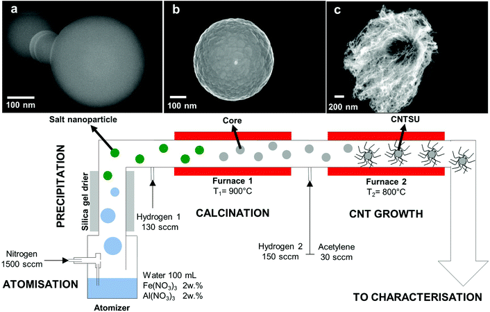
The strong sp2 bonds joining carbon atoms within a carbon nanotube (CNT) confer unique properties along their axes, either mechanically (elastic modulus of 1 TPa, tensile strength of 100 GPa for multiwall CNTs), electrically (multiwall CNTs can carry currents up to 109 A cm−2), or thermally (thermal conductivity of 3500 W m−1 K−1 for single wall CNTs at room temperature based on wall area).1 Individual CNT properties are limited by intra-CNT characteristics such as the degree of graphitization, length and chirality, whereas macroscopic materials composed of CNTs are often limited by the inter-CNT properties, such as the interface between individual CNTs or CNTs and other materials. Hybrid structures, composed of nano- and macro-materials with varying chemistries have been combined with CNTs to produce multi-functional behaviour for applications such as biotechnology, sensing, and energy storage.2–4 These hybrid materials make use of CNT properties as either a major or a minor constituent within a larger structure, whereby CNT density, morphology and binding with other materials must be optimized. On-going research efforts to address this challenge are developing production processes that enable hierarchical ordering of CNTs while retaining large volume-production capabilities. This work focuses a gas-phase process that produces a three-dimensional structure known as a carbon nanotube sea urchin (CNTSU) whereby CNTs are radially grown from a metal oxide core nanoparticle (see Fig. 1).Early accounts of the CNT sea-urchin architecture include magnetic hollow nickel microspheres covered with oriented CNTs,5 CNTs immobilised on hollow carbon spheres proposed as a conductive support for fuel cell electrocatalysts,6 boron nitride/CNT composite particles synthesised using a spray-pyrolysis route,7 CNT forests grown on spherical ceramic microparticles via CVD,8–10 bulk production of carbon nanotubes in fluidised beds,11,12 or boundary layer CVD synthesis of radial filled CNT structures.13 More recently the CNTSU architecture was proposed as a cathode material for Li–S batteries, with a cobalt core acting as a host material for sulphur and radially organised CNTs enabling efficient electron transport.14 Additional hierarchical structures have employed CNTs to enhance metal oxides for structural,15 electrochemical, and thermal applications,16,17 but often rely on physical interactions between CNTs and metal oxides18 (e.g. van der Waals) rather than covalent bonding. This article focuses on a process enabling CNT growth from Al–Fe oxide particles with diameters dp < 1 μm, which was first reported by Kim et al.19 where an aerosol of CNTSUs is continuously synthesised in the gas-phase. Owing to their enhanced heat transfer properties, with all CNTs being interlinked via a high thermal-conductivity core, thus enabling control of CNT–CNT junctions, these CNTSUs have found applications ranging from nanofluid coolant additives,20 additive to bulk heterojunction polymer–fullerene solar cells as an exciton dissociation medium21 and optical igniter in the explosion of nanoenergetic thermite materials.22 As shown on Fig. 1, an aqueous solution of aluminium nitrate Al(NO3)3 and iron nitrate Fe(NO3)3 is atomised in a nitrogen carrier gas, creating a polydisperse microdroplet aerosol. As water evaporates from the droplets, solute concentrations increase, eventually leading to precipitation of the metal nitrate salts, thus forming bimetallic salt nanoparticles (Fig. 1a) suspended in the gas-phase. These nanoparticles then undergo calcination in a high temperature reducing environment, typically a tube furnace with a small addition of hydrogen to the carrier gas, enabling the formation of composite nanoparticles that will act as floating substrates and catalysts for CNT growth (Fig. 1b). Acetylene (C2H2) and additional hydrogen is added to a second CVD furnace, resulting in CNTs growing radially from the surface of the cores, thus forming CNTSUs as shown in Fig. 1c. As an aerosol-based nanomaterial process,23 this synthesis route is continuous and solvent-free. It relies on cheap precursors and combines two widely used methods – spray pyrolysis and CVD – that are used to manufacture most of the world's industrial production of nanomaterials such as carbon black, TiO2 and other metal oxide nanopowders,23–26 or bulk CNT powder.1
The mechanism that leads to catalytic site formation on the CNTSU core surface has, thus far, not been fully explained. It has been suggested that Fe sites may segregate within the cores upon droplet precipitation due to differences in solubilities of aluminium nitrate and iron nitrate. This mechanism implies that the microstructure resulting from droplet precipitation is preserved through the harsh conditions in the calcination and growth furnaces.19 The same catalytic site formation mechanism was proposed by Kim et al.27 when iron nitrate is replaced with nickel nitrate. Little quantitative characterisation of the core chemical composition has been reported so far. Such information is important to envision applications where the core plays a functional role, such as in sensing or energy storage applications. In particular, knowing whether Al and Fe oxides form two segregated phases or an alloy has not been settled. Kim et al. showed that CNT loading can be controlled to some extent by tuning core composition and size,19,27 but no systematic optimisation of the process in terms of CNT loading and quality has yet been reported.
In the present work we seek to better understand the core composition and the mechanism of catalytic sites formation in order to optimise the synthesis method and support further scale-up of core Al–Fe materials functionalized by surface grown CNTs. We found that in our process, the urchin cores are composed of a partially-hollow AlxFeyOz alloy embedding small metallic crystallites acting as catalytic sites for CNT growth. This leads to the proposition of a new mechanism for catalytic site formation, whereby catalytic sites nucleate at the surface of the cores within the calcination furnace, effectively decoupling catalytic site formation and CNT growth from the initial metal nitrate precipitation stage. Building on this discovery, we anticipate that the CNTSU synthesis process is more versatile than what was originally thought, as it does not rely on the initial structure created upon droplet precipitation. For instance, we show that CNTSU morphology can be tuned independently of core size and composition by changing the operating parameters of the CVD growth furnace. This is of interest for applications where it is necessary to control the proportion of CNTs relative to core material, as some applications require minimal CNT loading.14 In that respect, a new in situ technique to monitor in-flight CNT growth on the surface of the cores is developed, using aerosol science methods that are usually applied for atmospheric chemistry and nanoparticle measurement from engine exhaust. Finally, in view of other applications where it is necessary to maximise CNT loading, we show that CNT loading and quality can be significantly improved with a novel hybrid aerosol-substrate CVD growth process that results in the formation of CNTSU carpets.
2. Experimental
2.1 CNTSU synthesis
The apparatus and typical conditions for CNTSU synthesis is described on Fig. 1. A bespoke one-jet Collison nebulizer is used to atomise an aqueous solution of aluminium nitrate and iron nitrate in a flow of nitrogen carrier gas (1500 sccm). The resulting aerosol (geometric mean diameter ∼1 μm as measured with an optical aerosol spectrometer) is then passed through a custom-made silica gel drier where nearly all of the stream moisture content is removed. The resulting dry metal nitrate salts nanoparticles then enter a calcination furnace (900 °C) together with an additional flow of hydrogen (130 sccm). Downstream of the first furnace, the resulting aerosol is further mixed with a flow of hydrogen (150 sccm) and a flow of acetylene (30 sccm) before entering the CVD growth furnace (800 °C). Total process time is ∼30 s with production rates of ∼10 mg h−1. The operating conditions shown on Fig. 1 are referred to as the nominal conditions in what follows. Further information on materials and apparatus can be found in ESI 1.†2.2 Ex situ characterisation
About 50 mg of cores were collected by filtration for XRD analysis downstream of furnace 2 at nominal conditions but without acetylene to avoid the formation of CNTs.All transmission electron microscope (TEM) and scanning electron microscope (SEM) samples were obtained by collecting particles, either cores or CNTSUs, on TEM grids or silicon wafers using the thermophoretic precipitator described in section 2.4.
Energy-dispersive X-ray spectroscopy (EDX) was performed on a ∼5 μm thick film of cores collected downstream of furnace 2 at nominal conditions but without acetylene to avoid the formation of CNTs. Cores were collected on a silicon wafer using the thermophoretic precipitator.
Raman spectroscopy was performed on the same sample (cores), as well as on a film of CNTSUs collected on a silicon wafer at nominal conditions, and on a film of substrate-grown CNTSUs as described in section 2.5. Further information can be found in ESI 1.†
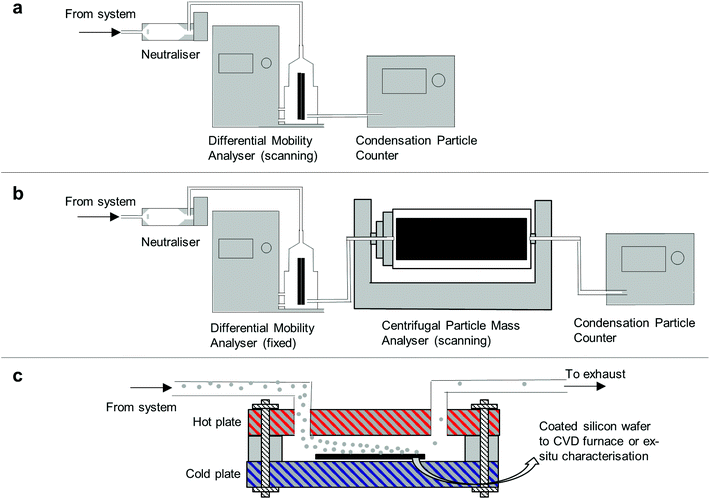
2.3 Scanning mobility particle sizer and centrifugal particle mass analyser
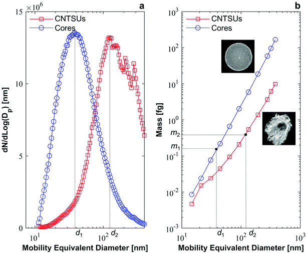
The Scanning Mobility Particle Sizer (SMPS) is a common in-line aerosol characterisation tool used to measure particle size distribution based on their electrical mobility equivalent diameter.28 As shown on Fig. 2a the aerosol to be characterized is imparted with a known bipolar charge distribution by collisions with gaseous ions within a device called neutraliser. The aerosol then enters a differential mobility analyser (DMA) where it is classified according to its mobility equivalent diameter. The concentration of classified particles is then measured with a condensation particle counter (CPC).29 Particle size distributions were measured using the SMPS downstream of furnace 2 to characterise cores and CNTSUs at nominal conditions.Additional in-line classification was conducted by a Centrifugal Particle Mass Analyser (CPMA, Cambustion), which classifies particles according to their mass-to-charge ratio.30 Particles are injected in between two rotating concentric cylinders, while a electrical potential is applied between both cylinders. Particle trajectories result from the balance between electrical and centrifugal forces acting onto them, classifying particles by their mass to charge ratio. Scanning the rotation speed of the cylinders results in a measured aerosol particle mass distribution when a CPC is used to count the resultant particles. The CPMA was operated downstream of a DMA as shown on Fig. 2b. A polydisperse aerosol, either cores or CNTSUs, enters the neutraliser and is classified in the DMA (10 L min−1 sheath), prior to being scanned by the CPMA. A lognormal distribution curve is fitted to each mass distribution in order to extract a representative particle mass for a given mobility.31 More information on the operating parameters of the CPMA and the fitting procedure is available in ESI 2.† This method was used downstream of furnace 2, both at nominal conditions to characterise CNTSUs and at nominal conditions but no acetylene to characterise cores in order to establish mass-mobility relationships.
2.4 Thermophoretic precipitator
A bespoke thermophoretic precipitator was designed to collect particles from the gas-phase onto a silicon wafer. The device allowed for deposition of a large area (∼5 cm2) film of cores with controlled thickness onto any substrate (not necessarily a filter) in order to enable the substrate-based CNTSU CVD growth experiment, see section 2.5. When compared to filter-transfer techniques, thermophoretic deposition allows films with lower contamination levels, more uniform and thickness-controlled film deposition. The thermophoretic precipitator consists of two aluminium plates separated by a thin (∼1 mm) gap created by a thermally insulating gasket as described on Fig. 2c. One plate is heated to ∼300 °C with a flat pad ceramic heater, while the other is water cooled to ∼10 °C. The aerosol entering the gap in-between the two plates experiences a net force from the hot plate to the cold side arising from the temperature gradient,32 which collects particles on a cold substrate (typically silicon).332.5 Substrate-based CNTSU CVD growth
Cores were collected downstream of furnace 1 with the system operated at nominal conditions onto a ∼1 × 1 cm silicon wafer using the thermophoretic precipitator. Collection time was ∼60 min to ensure full coverage of the wafer and >10 μm coating thickness as confirmed by SEM. The wafer was then transferred to a horizontal tube furnace where it underwent thermal CVD at atmospheric pressure, with flows of 100/100/400 sccm C2H4/H2/He, at 800 °C with a 20 min growth time and 15 min annealing time. The resulting CNTSUs were rapidly cooled in the growth atmosphere before purging the CVD chamber with helium. This standard setup has been described previously.343. Results and discussion
3.1 Structure and morphology of cores
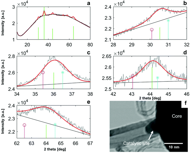
XRD analysis gave further detail of the core chemistry. In Fig. 4a the XRD measurements of the bare particle cores (no CNTs) show a broad maxima from 10–80° 2θ, which results from X-ray scattering from a largely disordered atomic structure. The large area from this broad maxima indicates the atomic structure of the core is substantially amorphous. Integrated analysis of the XRD signal intensity from 10–80° 2θ indicates that the total fraction of amorphous material within the cores is ∼13%.
Four peaks within the XRD identified on Fig. 4a were sufficiently defined for interpretation of the spectrum, which are shown on Fig. 4b–f. Crystalline peaks are relatively broad (∼1°) while the instrument broadening is <0.1°, which indicates that the crystallites dispersed in the sample are small.35 Quantification of crystallite size dSvia the Scherrer equation is shown on Table S1 in the ESI.† Results are relatively consistent across peaks, with Scherrer sizes ranging from dS = 5.8 nm to dS = 7.9 nm. The location and relative intensities of these crystalline peaks, as well as that of the other smaller peaks listed in ESI 3,† are compatible with a hercynite Al2FeO4 (CAS 00-034-0192)-magnetite Fe3O4 (CAS 00-019-0629) solid solution. Corresponding peak locations and relative intensities are shown by vertical lines on Fig. 3b–f. It can be seen that peak location for our sample falls in-between peak locations for hercynite and magnetite in all cases. Magnetite and hercynite both crystallise in a cubic system with the inverse and normal spinel structure respectively. Each peak is attributed to a given plane reflection in Table S1 (ESI†). Lattice parameter of magnetite–hercynite solid solution varies continuously with the degree of substitution,36 and using Veggard's rule the proportion xH of hercynite in the solid solution of crystalline material was found to be xH = 50–80%, as shown in the ESI.† The large range of xH can be attributed to the uncertainty of fitted broad peaks, possible stacking faults that are common in this Fe–Al–O system36 (especially with regards to peak 3), and inherent limitations to Veggard's formula.
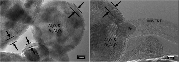
The approximate crystal sizes found in XRD coincides with the size of crystalline domains found in HRTEM. Metallic iron and iron carbide are not detectable in the XRD spectra, indicating that they form a minor constituent of the crystalline material. This finding corroborates the relatively limited amount of metallic iron found by HRTEM on either the bare cores or those with CNTs. The crystalline sizes of the metal oxides and metal carbides found in TEM (<10 nm) are compatible with catalytic CNT growth. It is the metallic species and carbides that are known to be efficient growth sites for CNTs by CVD.37 Experiments on substrate-based CNT growth, where CNTs were grown from cores collected downstream of furnace 1 (see section 3.3) suggest that these crystals nucleate in furnace 1, and may be reduced in furnace 2.
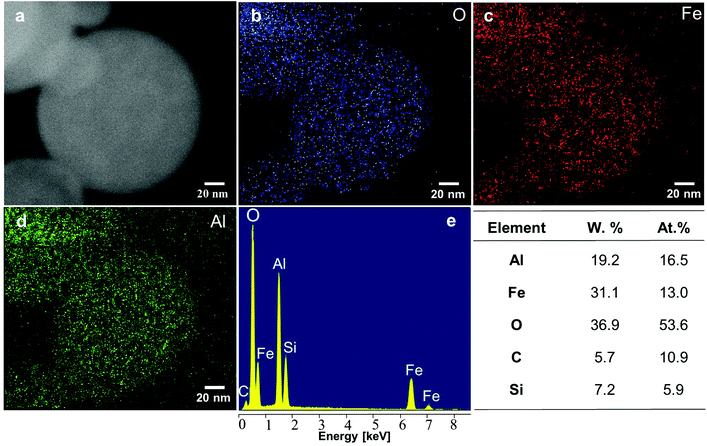
A sample with the same composition as the one analysed with XRD was therefore analysed with EDX in Fig. 5 in order to characterise the chemical composition of the cores. The presence of iron, aluminium, oxygen was measured (Fig. 5e), along with contributions of carbon and silicon that can be attributed to contamination (from the atmosphere and from the walls of furnace 2) and wafer background respectively. Quantitative composition analysis shown in Fig. 5f indicates that the atomic Al/Fe/O ratio is ∼1.4/1/4.1. This Al/Fe atomic ratio is close to what could be expected from the equal weight proportion of Al(NO3)3 and Fe(NO3)3 present in the atomiser precursor solution, meaning that the Al/Fe atomic ratio is ∼1.14 in the atomiser. EDX gives no indication that Al and Fe form two segregated phases in the amorphous part of the sample. As they form a mixed phase in the crystalline part of the sample it is reasoned that they also form an alloy in the remainder of the sample. This characterisation is of interest to envision new applications relying on the functionality of the metal oxide core for these CNTSUs. For instance the synthesis of CNTs from a hercynite composite with similar Al–Fe–O ratios by CVD from a FeOx–AlOOH xerogel as catalyst has been reported previously.38 Interestingly this hybrid material38 presents unusual magnetic properties that are different from those of the individual components of the CNT and hercynite, and good aqueous colloidal stability properties, which may pave the way for the application of CNTSUs to the preparation of composites with hydrosoluble polymers for EMI shielding.38
These results show that (a) cores are composed of small (<10 nm) crystallites of a hercynite–magnetite solid solution with a proportion of hercynite comprised between 50% and 80%, dispersed in an amorphous matrix that accounts for the majority of the sample. These crystallites are likely to nucleate in furnace 1 and act as metallic catalytic sites for the subsequent growth of CNTs. This mechanism for catalytic site formation is fundamentally different from the previously accepted mechanism. (b) Neither XRD nor EDX suggest that Al and Fe are segregated into distinct phases within the particle, which is not surprising as hercynite and magnetite form full solid solutions above 850 °C.36,39 Nonetheless, HRTEM analysis shows that reduced iron species at the surface of the particles are produced, possibly as a result of the reducing atmosphere within the second furnace. Results do not rule out the possibility that concentration gradients resulting from initial droplet precipitation exist within the cores,19 but it appears that the intimate mixing of Al(NO3)3 and Fe(NO3)3 within the initial droplets, and the diffusion of Al and Fe at elevated temperatures followed by rapid quenching within the system lead to the formation of an alloy. (c) Overall atomic ratio of Al/Fe/O was estimated to be 1.4/1/4.1 which is in agreement with initial precursor composition.
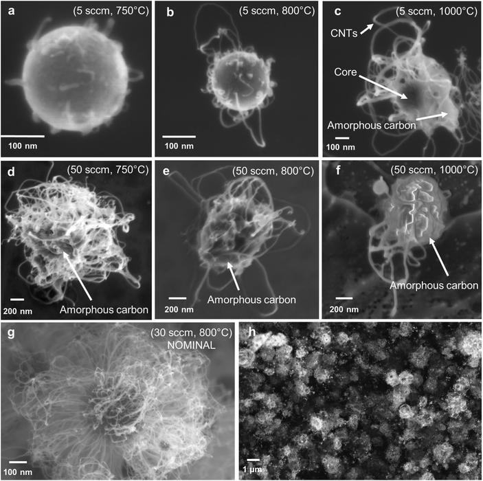
3.2 Optimisation of CNT growth
3.3 Substrate growth of CNTSUs by CVD
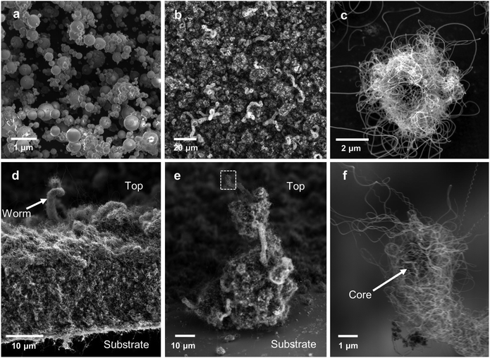
To demonstrate the broad applicability of the core materials for synthesis of hybrid hierarchical structures the cores were tested to determine their suitability for production of CNTs within stationary CVD reactor. As the properties of a hybrid structure to an extent depend on the mass ratio of primary constituents, increased CNT loadings may be beneficial for some applications. The CNT loading per core and their quality are limited in the continuous flow reactor by the residence time in furnace 2. To overcome this limitation, we have grown CNTs from the same cores in a standard CVD reactor, following the process described in section 2.5. This allows for a growth time of 20 min or more which is substantially longer than the ∼5 s available in the gas-phase process. The prolonged exposure to high temperatures will destroy any phase segregation that may arise due to preferential precipitation of Fe or Al nitrates during the droplet drying phase as proposed by Kim et al.19 Thus, successful growth of CNT materials from the cores indicates a more general mechanism of CNT growth that is thermodynamically stable and does not rely on metastable phase from the drying of nitrates.Starting from the ∼5 μm thick film of cores collected downstream of furnace 2, a ∼50 μm thick film of CNTs was grown by CVD as shown in Fig. 8d. Contrary to films deposited form aerosol-grown CNTSUs (Fig. 6h), Fig. 8b shows that substrate-based grown CNTSUs entangle to form a dense CNT carpet. The enhanced entanglement of the CNTs between cores leads to stronger connections between the metal oxide components, resulting in materials that are less fragile (handled with tweezers without breaking). Large diameter (∼5 μm) CNTSUs were found on the edges of the substrate (Fig. 8c) where the initial core packing density was low enough to ensure that they result from a single core. These are significantly larger than typical aerosol-grown CNTSUs (∼1 μm diameter). Interestingly, Fig. 7d–f show that in the rest of the sample higher core packing density leads to the formation of worm-like CNT structures. Fig. 8e and f show that these structures originate from a single core that ends up at the top of the structure upon growth termination, suggesting a root-growth mechanism from the cores, which is in agreement with the STEM picture shown in Fig. 4f.
Overall the successful growth of CNTs with the substrate-based method confirms that the CNTSU growth process is more robust than previously expected. Here cores are subjected to high temperatures for over 30 min, which is likely to enable significant solid-state diffusion within the core, meaning that the initial structure created upon droplet precipitation is likely to be destroyed, which does not prevent CNT growth. The findings of broader growth conditions offer the potential for hybrid metal–oxide/CNT structures that can be tailored to specific mass fractions for desired applications through control of the time-temperature CNT growth conditions. The resulting substrate grown structures have a distinct morphology from either deposited CNTSUs from the gas phase with enhanced inter-connections between cores. Further, the substrate-grown CNTSUs have unique morphology from traditional 1-D forest-grown CNTs with 3D radial growth of CNTs interlinking the hierarchical hybrid structure.
Raman spectra of cores, aerosol-grown CNTSUs, and substrate-grown CNTSUs are compared in Fig. 9. Aerosol-grown CNTSUs produce a Raman signal that is a combination of the Raman signal originating from the cores, and a contribution of the CNTs (D, G, and G′ peaks40). Substrate-grown CNTSUs produce a significantly stronger signal that can be attributed to CNTs only. The higher G/D ratio (∼1.5 vs. 1) for substrate-grown vs. aerosol-grown CNTSUs indicates less defects for CNTs produced with this technique.
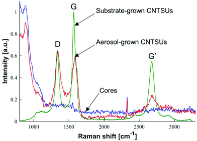 | ||
| Fig. 9 Raman spectra for cores collected downstream of furnace 2 at nominal conditions without acetylene, aerosol-grown CNTSUs (nominal conditions), and substrate-grown CNTSUs as shown on Fig. 8. Signal intensity was normalised by D band intensity, with equal normalisation factor for both cores and aerosol-grown CNTSUs. | ||
4. Conclusions
Emerging applications of hybrid functional materials such as biotechnology, sensing, and energy storage, require precise engineering of materials at the nano- and micro-scales to maximize benefits from unique materials such as CNTs. We provided a new mechanism of growth to describe a continuous flow method to create a hierarchical CNT sea urchin morphology where CNTs grow radially from a metal oxide nanoparticulate core. We found that the cores of these structures are composed of an alloy of aluminium and iron oxides into which small metallic crystallites of similar composition are embedded. These metallic crystallites are formed in the calcination step of the synthesis process and subsequently act as catalytic sites for the growth of carbon nanotubes. Harnessing this new insight enabled us to enhance the synthesis process by both in-line aerosol monitoring of CNT growth and by decoupling core synthesis from CNT growth. We demonstrate that limitation to CNT length and quality resulting from the previously reported gas-phase process are overcome with the first reported substrate-based CVD growth of CNTSUs enabling improved CNT loading and quality for CNTSUs compared to the aerosol process, together with the formation of unique worm-like CNT structures. These processes allow for high-throughput production of precisely-controlled heirarchical functional materials and are being scaled for industrial production.Availability of datasets
The datasets analyzed in this study are predominately included in this published article and the ESI.† Additional data is available at the following DOI https://doi.org/10.17863/CAM.20840.Conflicts of interest
There are no conflicts to declare.Acknowledgements
The authors thank Davor Copic and Shahab Ahmad for their help with CNT growth by CVD. Shahab Ahmad's help with Raman measurement is also acknowledged, together with that of Brian Graves and Chris Nickolaus (Cambustion Ltd) for CPMA experiments, and Laura Maggini for TGA experiments. Jean de La Verpilliere is supported by the EPSRC Cambridge NanoDTC, EP/G037221/1, the Cambridge Home EU Scholarship Scheme (CHESS) and the Schiff Foundation Studentships. Adam Boies is supported by the EPSRC ANAM grant (EP/M015211/1). Michael De Volder is supported by an ERC starting grant (HIENA - 337739). Sarah Jessl is supported by the ERC starting grant (HIENA-337739) and the EPSRC Studentship (Hierarchical Carbon nanostructures, 1470335).References
- M. F. L. De-Volder, S. H. Tawfick, R. H. Baughman, A. J. Hart, M. F. L. De Volder, S. H. Tawfick, R. H. Baughman and A. J. Hart, Science, 2013, 339, 535–539 CrossRef CAS PubMed.
- M. P. P. Landry, H. Ando, A. Y. Y. Chen, J. Cao, V. I. I. Kottadiel, L. Chio, D. Yang, J. Dong, T. K. K. Lu and M. S. S. Strano, Nat. Nanotechnol., 2017, 12, 368–377 CrossRef CAS PubMed.
- D. Gu, W. Li, F. Wang, H. Bongard, B. Spliethoff, W. Schmidt, C. Weidenthaler, Y. Xia, D. Zhao and F. Schüth, Angew. Chem., Int. Ed., 2015, 54, 7060–7064 CrossRef CAS PubMed.
- X. Shi, A. von dem Bussche, R. H. Hurt, A. B. Kane and H. Gao, Nat. Nanotechnol., 2011, 6, 714–719 CrossRef CAS PubMed.
- M. Han, W. Zhang, C. Gao, Y. Liang, Z. Xu, J. Zhu and J. He, Carbon, 2006, 44, 211–215 CrossRef CAS.
- Y. Piao, K. An, J. Kim, T. Yu and T. Hyeon, J. Mater. Chem., 2006, 16, 2984 RSC.
- A. B. D. Nandiyanto, Y. Kaihatsu, F. Iskandar and K. Okuyama, Mater. Lett., 2009, 63, 1847–1850 CrossRef CAS.
- D. He, M. Bozlar, M. Genestoux and J. Bai, Carbon, 2010, 48, 1159–1170 CrossRef CAS.
- D. He, H. Li, W. Li, P. Haghi-Ashtiani, P. Lejay and J. Bai, Carbon, 2011, 49, 2273–2286 CrossRef CAS.
- R. Xiang, G. Luo, W. Qian, Y. Wang, F. Wei and Q. Li, Chem. Vap. Deposition, 2007, 13, 533–536 CrossRef CAS.
- Z. Chen, D. Y. Kim, K. Hasegawa, T. Osawa and S. Noda, Carbon, 2014, 80, 339–350 CrossRef CAS.
- D. Y. Kim, H. Sugime, K. Hasegawa, T. Osawa and S. Noda, Carbon, 2011, 49, 1972–1979 CrossRef CAS.
- F. S. Boi, G. Mountjoy and M. Baxendale, Carbon, 2013, 64, 516–526 CrossRef.
- T. Chen, B. Cheng, G. Zhu, R. Chen, Y. Hu, L. Ma, H. Lv, Y. Wang, J. Liang, Z. Tie, Z. Jin and J. Liu, Nano Lett., 2016 DOI:10.1021/acs.nanolett.6b04433.
- A. Azarniya, S. Sovizi, A. Azarniya, M. R. Rahmani Taji Boyuk, T. Varol, P. Nithyadharseni, H. R. Madaah Hosseini, S. Ramakrishna and M. V. Reddy, Nanoscale, 2017, 9, 12779–12820 RSC.
- M. I. Boulos, J. Jurewicz, C. Nessim and C. Normand, PCT/CA, US7572315, 2004 Search PubMed.
- G. D. Nessim, Nanoscale, 2010, 2, 1306 RSC.
- M. M. Rahman, I. Sultana, Z. Chen, M. Srikanth, L. H. Li, X. J. Dai and Y. Chen, Nanoscale, 2015, 7, 13088–13095 RSC.
- S. H. Kim, C. Wang and M. R. Zachariah, J. Nanopart. Res., 2011, 13, 139–146 CrossRef CAS.
- Z. H. Han, B. Yang, S. H. Kim and M. R. Zachariah, Nanotechnology, 2007, 18, 105701 CrossRef.
- S.-Y. Park, W.-D. Kim, D.-G. Kim, J.-K. Kim, Y.-S. Jeong, J. H. Kim, J. K. Lee, S. H. Kim and J.-W. Kang, Sol. Energy Mater. Sol. Cells, 2010, 94, 750–754 CrossRef CAS.
- J. H. Kim, S. B. Kim, M. G. Choi, D. H. Kim, K. T. Kim, H. M. Lee, H. W. Lee, J. M. Kim and S. H. Kim, Combust. Flame, 2015, 162, 1448–1454 CrossRef CAS.
- T. T. Kodas and M. J. Hampden-Smith, Aerosol Processing of Materials, Wiley-VCH, USA, 1999 Search PubMed.
- W. J. Stark and S. E. Pratsinis, Powder Technol., 2002, 126, 103–108 CrossRef CAS.
- M. E. Vance, T. Kuiken, E. P. Vejerano, S. P. McGinnis, M. F. Hochella and D. R. Hull, Beilstein J. Nanotechnol., 2015, 6, 1769–1780 CrossRef CAS PubMed.
- F. Piccinno, F. Gottschalk, S. Seeger and B. Nowack, J. Nanopart. Res., 2012, 14, 1109 CrossRef.
- W. D. Kim, J. Y. Ahn, D. G. Lee, H. W. Lee, S. W. Hong, H. S. Park and S. H. Kim, J. Colloid Interface Sci., 2011, 362, 261–266 CrossRef CAS PubMed.
- S. C. Wanga and R. C. Flagan, Aerosol Sci. Technol., 1990, 13, 230–240 CrossRef.
- R. C. Flagan, KONA Powder Part. J., 2008, 26, 254–268 CrossRef CAS.
- J. S. Olfert and N. Collings, J. Aerosol Sci., 2005, 36, 1338–1352 CrossRef CAS.
- B. Graves, J. Olfert, B. Patychuk, R. Dastanpour and S. Rogak, Aerosol Sci. Technol., 2015, 49, 589–598 CrossRef CAS.
- W. C. Hinds, Aerosol Technology: Properties, Behavior, and Measurement of Airborne Particles, Wiley-VCH Verlag GmbH, New-York, 2nd edn, 1999 Search PubMed.
- D. Gonzalez, A. G. Nasibulin, A. M. Baklanov, S. D. Shandakov, D. P. Brown, P. Queipo and E. I. Kauppinen, Aerosol Sci. Technol., 2005, 39, 1064–1071 CrossRef CAS.
- S. Ahmad, D. Copic, C. George and M. De Volder, Adv. Mater., 2016, 1–6 Search PubMed.
- J. I. Langford and A. J. C. Wilson, J. Appl. Crystallogr., 1978, 11, 102–113 CrossRef CAS.
- A. C. Turnock and H. P. Eugster, J. Petrol., 1962, 3, 533–565 CrossRef CAS.
- S. S. Lee, C. Zhang, Z. A. Lewicka, M. Cho, J. T. Mayo, W. W. Yu, R. H. Hauge and V. L. Colvin, J. Phys. Chem. C, 2012, 116, 10287–10295 CAS.
- N. J. Morales, S. Goyanes, C. Chiliotte, V. Bekeris, R. J. Candal and G. H. Rubiolo, Carbon, 2013, 61, 515–524 CrossRef CAS.
- U. Golla-Schindler, Am. Mineral., 2005, 90, 1278–1283 CrossRef CAS.
- M. S. Dresselhaus, G. Dresselhaus, R. Saito and a. Jorio, Phys. Rep., 2005, 409, 47–99 CrossRef.
Footnote |
| † Electronic supplementary information (ESI) available. See DOI: 10.1039/c7nr09534a |
| This journal is © The Royal Society of Chemistry 2018 |

