Synthesis of NiTiO3–Bi2MoO6 core–shell fiber-shaped heterojunctions as efficient and easily recyclable photocatalysts†
Yuming
Jin‡
a,
Xiaofeng
Shen‡
a,
Zixiao
Liu
b,
Zhaojie
Wang
b,
Bo
Zhu
b,
Pengfei
Xu
a,
Li
Luo
a and
Lisha
Zhang
 *a
*a
aState Key Laboratory for Modification of Chemical Fibers and Polymer Materials, State Environmental Protection Engineering Center for Pollution Treatment and Control in Textile Industry, College of Environmental Science and Engineering, Donghua University, Shanghai, 201620, China. E-mail: lszhang@dhu.edu.cn; Fax: +86-21-67792522; Tel: +86-21-67792548
bCollege of Materials Science and Engineering, Donghua University, Shanghai 201620, China
First published on 24th November 2017
Abstract
Development of efficient and recyclable photocatalysts has drawn more and more attention. Herein, we have prepared a kind of core–shell fiber-shaped NiTiO3–Bi2MoO6 heterojunction as an efficient and easily recyclable visible-light-driven photocatalyst. NiTiO3 nanofibers have been obtained by an electrospinning–calcination method; and in situ growth of Bi2MoO6 is conducted on the surface of NiTiO3 by a simple solvothermal method. NiTiO3–Bi2MoO6 heterojunctions are composed of NiTiO3 nanofibers with a diameter of about 150 nm whose surfaces are decorated by Bi2MoO6 nanoneedles with a diameter of ∼8 nm and length of ∼35 nm. Under visible light irradiation, NiTiO3–Bi2MoO6 heterojunctions exhibit significantly high photocatalytic activities compared with NiTiO3, Bi2MoO6 and a mechanical mixture (22 wt% NiTiO3 + 78 wt% Bi2MoO6) when rhodamine B (RhB) or 4-chlorophenol (4-CP) are selected as model pollutants. For example, NiTiO3–Bi2MoO6 heterojunctions achieve the highest photodegradation efficiency of RhB (97.2%) compared to 21.9% by NiTiO3, 40.3% by Bi2MoO6 and 45.0% by the mechanical mixture. The enhanced photocatalytic activities can be mainly attributed to the efficient separation of photogenerated electron–hole pairs. During the photocatalytic degradation of RhB, superoxide radical ions (˙O2−) and photogenerated holes (h+) are detected as the main active species. Moreover, NiTiO3–Bi2MoO6 heterojunctions can be recycled by sedimentation and still possess excellent stability. Therefore, NiTiO3–Bi2MoO6 heterojunctions have great potential to act as efficient and recyclable photocatalysts in practical applications of environmental purification.
1. Introduction
Environmental problems, especially organic pollutants (such as benzoapyrene, hexachlorocyclohexane and 4-chlorophenyl) in water, which pose a severe threat to human health, are attracting more and more attention.1–3 To solve this serious problem, photocatalysis technology has been developed due to its low cost, stability and moderate reaction conditions, which offers an environmentally friendly and energy-efficient method for environmental purification.4 The key of photocatalytic technology is to develop efficient visible-light-driven (VLD) photocatalysts.1,5,6 Currently, many kinds of VLD photocatalysts have been well designed and prepared, including simple oxides (m-Bi2O47), metal sulfides (Ag2S–BiOCOOH8), complex oxides (Bi2WO69–12) and non-mental materials (C3N413–15). Among these photocatalysts, nickel titanate (NiTiO316) with a band gap of 2.18 eV has been demonstrated to be a promising VLD photocatalyst. Powder-shaped NiTiO3 photocatalysts have been synthesized, including nanorods,17 nanoparticles18 and nanowires.19 For example, NiTiO3 nanorods can degrade 70% of nitrobenzene after 2 hours under visible light irradiation.17 For the development of their practical photocatalytic application, it is still necessary to optimize the VLD photocatalytic activity of NiTiO3 nanomaterials.It is well known that the construction of heterojunctions between different materials (TiO2 and C3N4)20,21 is an efficient way to improve the photocatalytic performance. To improve the photocatalytic activity of NiTiO3, some NiTiO3-based heterojunctions have been developed, such as NiTiO3–Ag3VO4 nanoparticles,22 NiTiO3–CdS nanoparticles,23 mesoporous NiTiO3–C3N4,24 and NiTiO3–Fe2O3 nanofibers.25 These NiTiO3-based heterojunctions exhibit enhanced photocatalytic activity compared to pure NiTiO3 photocatalysts. For example, Yang Qu et al. have reported that NiTiO3–CdS heterojunctions can degrade 90% of Cr(VI) after 2 h under visible light irradiation, which is higher than that (70%) by pure NiTiO3 nanorods.23 However, these powder-shaped photocatalysts also suffer from several drawbacks, such as complex preparation process, recycling difficulty and unsatisfactory photocatalytic activity.
Recently, bismuth-based photocatalysts have been reported to have excellent photocatalytic activities under visible light irradiation.26–28 Among the bismuth-based semiconductors, Bi2MoO6 with a band gap of about 2.66 eV has been prepared as a promising VLD photocatalyst to degrade organic pollutants due to its broad visible-light range and long photogenerated electron-pair lifetime.11,28–30 Meanwhile, Bi2MoO6 has been widely used to form heterojunctions with other materials to enhance the photocatalytic efficiency, such as Bi2MoO6–sulfide (Bi2MoO6–CdS14), Bi2MoO6–metal oxide (Bi2MoO6–TiO231) and Bi2MoO6–carbon (Bi2MoO6–graphene26). These heterojunctions show a significant increase in photocatalytic activity for degrading organic pollutants. Bi2MoO6 may be a potential candidate as a co-catalyst for NiTiO3 due to its well-matched band gaps, which can suppress the recombination of photoinduced charge carries. To our knowledge, there is no report on the synthesis of NiTiO3–Bi2MoO6 heterojunctions.
The electrospinning method has been recognized as an efficient technique to prepare nonwoven cloth and nanofibers which are easily recyclable. By using electrospinning-assisted methods, our group has prepared several efficient and easily recyclable photocatalysts, including Ta3N5–Pt nonwoven cloth,32 Fe2O3–AgBr nonwoven cloth33 and Ta3N5/Bi2MoO6 core–shell nanofibers.34 However, these are just preliminary works to fabricate composite photocatalysts by the electrospinning method. It is of great importance to further develop other inexpensive, efficient and recyclable photocatalysts. Herein, we developed novel NiTiO3–Bi2MoO6 core–shell fiber-shaped heterojunctions as an efficient and easily reusable photocatalyst. NiTiO3–Bi2MoO6 core–shell fiber-shaped heterojunctions were obtained through an electrospinning–calcination–solvothermal method. Importantly, NiTiO3–Bi2MoO6 heterojunctions exhibited higher photocatalytic activity in degrading organic pollutants (such as RhB and 4-CP) under visible light irradiation than pure NiTiO3 or Bi2MoO6. Furthermore, the mechanism of the advantageous photocatalytic activity was also proposed.
2. Experimental section
2.1 Synthesis of NiTiO3
NiTiO3 nanofibers were prepared by an electrospinning–calcination method. Typically, C4H6O4Ni·4H2O (3 mmol) was dissolved in a mixture of N,N-dimethylformamide (5 mL) and ethylene glycol (5 mL). After 30 min of magnetic stirring, C16H36O4Ti (1 mL) and PVP (0.7 g) were added into the above solution. After magnetically stirring for 24 h, the solution was then loaded into a plastic syringe. A voltage as high as 14 kV was applied between the needle and ground at a distance of 16 cm. The feeding rate of the syringe pump was set at 0.4 mL h−1 constantly, with a room temperature of 28 °C and constant humidity at 30%. The resulting nonwoven material was collected and followed by calcination at 700 °C for 6 h in a muffle furnace to produce NiTiO3 nanofibers.2.2 Synthesis of NiTiO3–Bi2MoO6 heterojunctions
The in situ growth of Bi2MoO6 on the surface of NiTiO3 nanofibers was realized by a simple solvothermal method. Typically, Bi(NO3)3·5H2O (2 mmol) and Na2MoO4·2H2O (1 mmol) were added into a mixture of ethylene glycol (30 mL) and ethanol (10 mL) aqueous solution respectively. Then NiTiO3 nanofibers (1 mmol, ∼150 mg) were added into the solution and magnetically stirred for 6 h. The solution was then transferred into an autoclave, followed by a solvothermal treatment at 160 °C for 24 h. The obtained sample was centrifuged and rinsed with ethanol four times and then dried for another 24 h. By comparison, Bi2MoO6 nanoparticles were also prepared by using the above method without NiTiO3 nanofibers. The characterizations of the photocatalysts are shown in the ESI.†2.3 Measurements of photocatalytic activity
In photocatalytic tests, 30 mg of photocatalyst was dispersed into 50 mL RhB aqueous solution (10 mg L−1) or 50 mL 4-CP aqueous solution (1 mg L−1), respectively.14 Firstly, the solution was stirred in darkness for 30 min to ensure that organic contaminants and photocatalysts reached an adsorption–desorption equilibrium. Then, the photocatalytic activities were measured by degrading the RhB and 4-CP contaminants at room temperature under a Xe lamp equipped with a UV-cutoff filter (wavelength λ > 400 nm). During the photocatalytic process, 1 mL of solution was collected every 20 min and then centrifuged. A UV-3101PC UV-vis spectrometer (Shimadzu) was used to measure the concentration of RhB; and high-performance liquid chromatography (HPLC, Agilent 1100 series) was used to measure the concentration of 4-CP. Tests of total organic carbon (TOC), radical trapping and photocatalytic stability were carried out and are shown in the ESI.†3. Results and discussion
3.1 Preparation and characterization of NiTiO3–Bi2MoO6
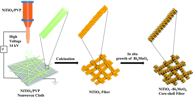
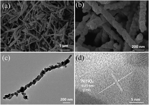
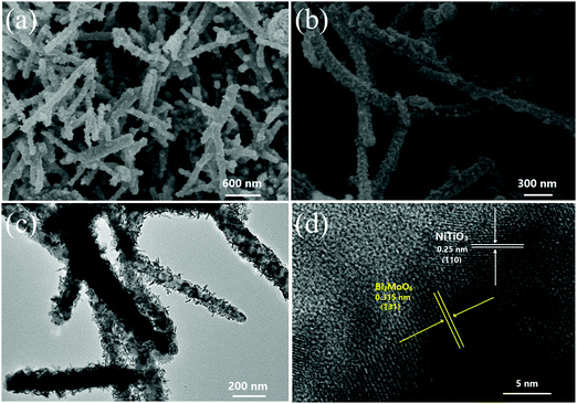
NiTiO3–Bi2MoO6 heterojunctions were obtained by an electrospinning–calcination–solvothermal method (Fig. 1). Firstly, NiTiO3–PVP nonwoven cloth was prepared by an electrospinning method. The as-prepared nonwoven cloth was green, and it became yellow after the calcination at 700 °C for 6 h. The sizes and morphologies of the calcinated nonwoven cloth were further studied by SEM and TEM images (Fig. 2). The calcinated nonwoven cloth is composed of plenty of nanofibers with diameters of ∼150 nm and lengths of 1∼2 μm (Fig. 2a). In fact, these nanofibers are constructed from nanoparticles with diameters of 50–70 nm (Fig. 2b). The TEM image (Fig. 2c) further confirms that the nanofibers consist of nanoparticles. The high-resolution TEM image (Fig. 2d) clearly displays one set of lattice fringes. The lattice fringe with a spacing of 0.25 nm is in good agreement with the value of the NiTiO3 (110) plane, which indicates the formation of NiTiO3 nanofibers.The second step was to grow Bi2MoO6 on the surface of NiTiO3 nanofibers by a solvothermal method to form NiTiO3–Bi2MoO6 heterojunctions. The SEM images (Fig. 3a and b) reveal that NiTiO3–Bi2MoO6 heterojunctions are also composed of nanofibers. Obviously, one can find that there are many small nanoneedles on the surface of the NiTiO3 nanofibers. The diameter of the nanofibers increases to ∼185 nm, due to the coating of the nanoneedles. Further information about the NiTiO3–Bi2MoO6 heterojunctions can be obtained from TEM images (Fig. 3c and d). The TEM images confirm that the sample is composed of nanofibers whose surface is decorated with plenty of nanoneedles. These nanoneedles have a diameter of ∼8 nm and length of ∼35 nm. The high-resolution TEM image (Fig. 3d) taken from the nanofiber demonstrates that the lattice spacings are 0.25 nm and 0.315 nm, which are in accordance with the values of the NiTiO3 (110) plane and Bi2MoO6 (113) plane, respectively. The above results confirm the formation of NiTiO3–Bi2MoO6 core–shell fibers.
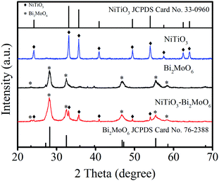
The XRD patterns of the NiTiO3–Bi2MoO6 heterojunctions, NiTiO3 nanofibers and Bi2MoO6 nanoparticles were further studied for investigating the phase of the as-prepared photocatalysts (Fig. 4). The diffraction peaks of NiTiO3 at 24.1°, 33.1°, 35.7°, 40.9°, 49.4° and 54.0° are assigned to the (012), (104), (110), (113), (024), (116) and (018) crystal planes (JCPDS Card No. 33-0960) respectively. In addition, the diffraction peaks of Bi2MoO6 at 28.3°, 32.6°, 46.7° and 55.5° are assigned to the (131), (002), (202) and (331) crystal planes (JCPDS Card No. 76-2388) respectively. It is obvious that the XRD patterns of the NiTiO3–Bi2MoO6 heterojunctions can be indexed to a mixture of NiTiO3 and Bi2MoO6, and no trace of any impurity peak was observed in the XRD pattern of NiTiO3–Bi2MoO6 which indicated the high purity of these heterojunctions.
The nitrogen adsorption–desorption isotherms of NiTiO3 nanofibers, Bi2MoO6 nanoparticles and NiTiO3–Bi2MoO6 heterojunction samples were also investigated (Fig. 5). The Brunauer–Emmett–Teller (BET) surface area of the NiTiO3 nanofibers is calculated to be 3.6 m2 g−1, while that of the Bi2MoO6 nanoparticles is 34.6 m2 g−1. Interestingly, after the decoration of Bi2MoO6 nanoneedles on the surface of the NiTiO3 nanofibers, the resulting NiTiO3–Bi2MoO6 heterojunction exhibits a greatly enhanced BET surface area (∼37.0 m2 g−1) compared with the NiTiO3 nanofibers, which should result from the introduction of Bi2MoO6 nanoneedles with large surface area. Furthermore, we also calculated the pore size distribution from the desorption branches, which reveals the existence of nanopores. The NiTiO3 nanofibers, Bi2MoO6 nanoparticles and NiTiO3–Bi2MoO6 heterojunction samples have a broad pore size distribution centered at about 31 nm, 22 nm and 22 nm respectively. The presence of nanopores may serve as transport paths for organic pollutant molecules.
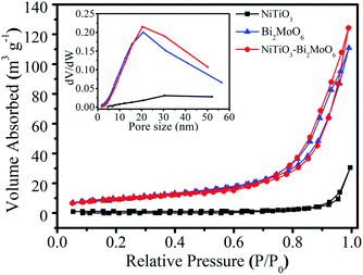 | ||
| Fig. 5 Nitrogen adsorption–desorption isotherms of NiTiO3, Bi2MoO6 and NiTiO3–Bi2MoO6 heterojunctions. | ||
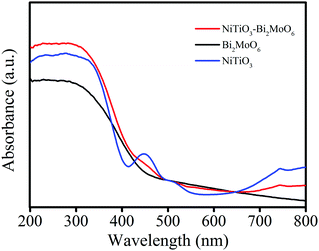
The optical absorption of NiTiO3–Bi2MoO6 heterojunctions as well as NiTiO3 fibers and Bi2MoO6 was measured by a UV-vis-NIR spectrometer (Fig. 6). The pure NiTiO3 nanofibers exhibit an intense absorption in the visible light region with an absorption edge around 545 nm, which is similar to a previous report.18 Two absorption bands at about 450 nm and 510 nm are observed due to the crystal field splitting of NiTiO3 with the 3d8 band associated with Ni2+ splitting into two sub-bands, which can be called Ni2+ → Ti4+ charge-transfer bands.35 In addition, the pure Bi2MoO6 exhibits an absorption edge around 460 nm. After the decoration of Bi2MoO6 on the surface of NiTiO3, NiTiO3–Bi2MoO6 heterojunctions display a broad phtotoabsorption from ultraviolet to visible light with an edge around 540 nm. This fact reveals that NiTiO3–Bi2MoO6 heterojunctions have a broad photoabsorption region, resulting in great potential as an excellent VLD photocatalyst.
3.2 Photocatalytic performance under visible light irradiation
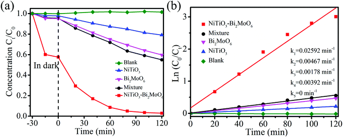
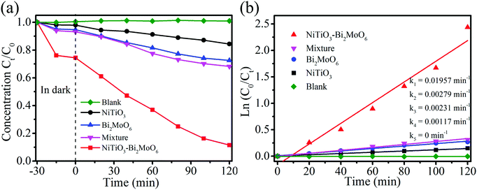
RhB, which is a kind of dye with color, was chosen as a representative pollutant to test the photocatalytic performance of NiTiO3–Bi2MoO6 heterojunctions. For comparison, NiTiO3 nanofibers, Bi2MoO6 nanoparticles and a mechanical mixture (22 wt% NiTiO3 nanofibers + 78 wt% Bi2MoO6 nanoparticles) were also applied to test their photocatalytic performance under visible light irradiation. RhB displays a major absorption band centered at 554 nm, which can be used to measure the photocatalytic degradation efficiency (Fig. 7a). After 30 min of magnetic stirring in darkness, the NiTiO3 nanofibers, the Bi2MoO6 nanoparticles and the mixture can adsorb 2.1%, 4.6% and 4.9% RhB, respectively. The low adsorption efficiency (2.1%) of RhB by NiTiO3 nanofibers is associated with their low surface area (3.6 m2 g−1), while the low adsorption efficiency (4.6%) by Bi2MoO6 nanoparticles should be attributed to the fact that Bi2MoO6 nanoparticles are easily aggregated and there are very limited macropores (as shown in Fig. S1, ESI†). Interestingly, the adsorption efficiency (∼40%) of RhB by NiTiO3–Bi2MoO6 heterojunctions is greatly higher than that from other samples, which should result from the higher surface area (37.0 m2 g−1) and hierarchical pores consisting of nanopores among the nanoneedles and/or nanofibers as well as macropores among the nanofibers (confirmed by Fig. 2a, b and 5). Under visible-light irradiation, the blank control indicates that no RhB can be degraded without photocatalysts, and NiTiO3 can degrade 21.9% RhB after 120 min. With Bi2MoO6 as the photocatalyst, 40.3% RhB can be degraded in 120 min. Interestingly, when NiTiO3–Bi2MoO6 heterojunctions are applied as photocatalysts, the photocatalytic efficiency is as high as 97.2% after 120 min under visible light irradiation. Obviously, NiTiO3–Bi2MoO6 heterojunctions have the highest photocatalytic activity among all the above materials. To further reveal the role of the heterojunction, RhB degradation by the mechanical mixture (22 wt% NiTiO3 + 78 wt% Bi2MoO6) was also conducted. The mechanical mixture reveals a weak photocatalytic activity, degrading 45.0% of RhB after 120 min under visible light irradiation. This fact shows that the formation of heterojunctions between NiTiO3 and Bi2MoO6 is crucial for the enhancement of photocatalytic performance. To quantitatively evaluate the kinetics of the RhB degradation reaction by all prepared materials, degradation rates are fit by using the pseudo-first-order mode which is in the type of Ln(C0/Ct) = kt36,37 (Fig. 7b). C0 and Ct in the above formula represent the original concentration of RhB and concentration of RhB at the specific time t. k in the above formula is a kinetic rate constant in the unit of min−1 which may vary with different photocatalysts. The kinetic rate constant of NiTiO3–Bi2MoO6 heterojunctions (0.02592 min−1) is much higher than those of NiTiO3 fibers (0.00178 min−1), Bi2MoO6 (0.00392 min−1), the mechanical mixture (0.00467 min−1). Based on the above results, one can conclude that NiTiO3–Bi2MoO6 heterojunctions are much more active than NiTiO3 fibers, Bi2MoO6 and the mechanical mixture.To further demonstrate that the photocatalytic performance actually results from the excitation of the NiTiO3–Bi2MoO6 photocatalyst instead of a dye sensitization mechanism, colorless organic pollutant 4-CP was chosen as the example pollutant. Degradation of 4-CP was measured by high-performance liquid chromatography (Fig. 8a). NiTiO3, Bi2MoO6, and the mechanical mixture can adsorb 1.9%, 4.8% and 6% 4-CP respectively after 30 min with magnetic stirring in darkness. NiTiO3–Bi2MoO6 heterojunctions adsorb 27% 4-CP under the same conditions, resulting from their high surface area (37.0 m2 g−1) and hierarchical pores. In the subsequent photocatalytic process, the blank control indicates that no 4-CP is degraded without photocatalysts. With pure NiTiO3 or Bi2MoO6 as photocatalysts, the photocatalytic degradation efficiency of 4-CP is 13% or 28% after 120 min, respectively. The degradation efficiency of the mechanical mixture (22 wt% NiTiO3 + 78 wt% Bi2MoO6) is only 30% after 120 min. Importantly, when the NiTiO3–Bi2MoO6 heterojunction is used as the photocatalyst, 91% 4-CP can be degraded under visible light irradiation after 120 min, which is better than NiTiO3, Bi2MoO6 and even the mechanical mixture. The kinetic curves are shown in Fig. 8b. The kinetic rate constant of the NiTiO3–Bi2MoO6 heterojunctions (0.01957 min−1) is much higher than those of the NiTiO3 fibers (0.00117 min−1), Bi2MoO6 (0.00231 min−1), mechanical mixture (0.00179 min−1). Obviously, NiTiO3–Bi2MoO6 heterojunctions exhibit the best photocatalytic activities. In addition, GC/MS analysis reveals that by using NiTiO3–Bi2MoO6 photocatalysts, there are six predominant intermediate products at 30 min of the photodegradation of 4-CP (Fig. S2 and Table S1, ESI†).
Mineralization of organic pollutants is an important aspect in pollutant treatment. A typical way to determine the mineralization degree of organic pollutants is to measure the total organic carbon (TOC). The mineralization degree of RhB was studied by adding 250 mg NiTiO3–Bi2MoO6 photocatalyst in 250 mL RhB aqueous solution (50 mg L−1) with magnetic stirring under visible light irradiation. The TOC value continuously decreases with the increase of irradiation time, which indicates that RhB is steadily mineralized (Fig. 9). After 7 h of reaction, the TOC value decreases from 43.48 mg L−1 to 23.95 mg L−1, revealing that RhB mineralization reaches a high ratio of 45%. This fact shows that NiTiO3–Bi2MoO6 photocatalysts can efficiently mineralize organic pollutants under visible light irradiation.
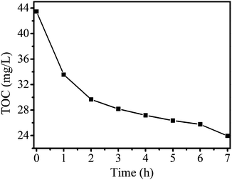 | ||
| Fig. 9 TOC removal during RhB (50 mg L−1, 250 mL) degradation in the presence of NiTiO3–Bi2MoO6 heterojunctions (250 mg) under visible light irradiation. | ||
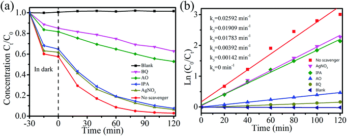
To further explore the mechanism of photocatalytic degradation, it is crucial to find out the major active species responsible for the degradation of organic pollutants with NiTiO3–Bi2MoO6 heterojunctions during the photocatalytic process. Isopropyl alcohol (IPA), benzoquinone (BQ), ammonium oxalate (AO) and AgNO3 are commonly used to capture hydroxyl free radicals (˙OH), superoxide radicals (˙O2−), photogenerated holes (h+) and electrons (e−), respectively.38 By adding four different scavengers in RhB solution with NiTiO3–Bi2MoO6 heterojunctions, trapping experiments were conducted to find out the most effective species (Fig. 10a). When IPA or AgNO3 is added, the degradation efficiency of RhB remains 92.4% or 93.6%, which is close to the result (∼97.2%) without scavengers. This fact indicates that ˙OH and e− are not the major active species responsible for RhB degradation. On the contrary, with the addition of BQ or AO, the degradation efficiency of RhB decreases to 37.1% or 47.1%, indicating that the photocatalytic activities can be significantly suppressed. The kinetic rate constant decreases dramatically from 0.02592 min−1 to 0.00142 min−1 and 0.00392 min−1 respectively (Fig. 10b). These facts verify that O2− and h+ are the major active species in the photocatalytic degradation of RhB with NiTiO3–Bi2MoO6 heterojunctions.
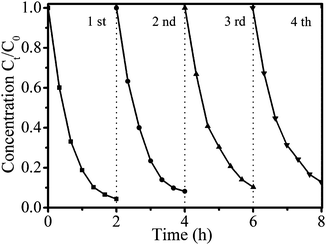
The stability of the NiTiO3–Bi2MoO6 heterojunctions is a critical factor for practical application. Four consecutive runs of photocatalytic tests were conducted to measure the stability (Fig. 11). After each cycle, NiTiO3–Bi2MoO6 heterojunctions were separated by centrifugation from solution, washed thoroughly with deionized water and then dried for the next use. The recycling efficiency of NiTiO3–Bi2MoO6 heterojunctions is determined to be 95.1% in each cycle. After four cycles, the degradation efficiency of RhB has a very slight decrease from 97.2% at the first cycle to 93.3% at the fourth cycle (Fig. 11). This slight decrease in degradation efficiency should result from the imperfect centrifugation efficiency (95.1%) instead of the loss of photocatalytic activity. Furthermore, we investigated the chemical stability of NiTiO3–Bi2MoO6 heterojunctions by analyzing the Ni, Ti, Bi, and Mo concentration in the clear solution after the centrifugation. Inductively coupled plasma results (Table S2, ESI†) indicate that the concentrations of all metal elements (Ni, Ti, Bi, Mo) are below 0.01 μg mL−1, which suggests that NiTiO3–Bi2MoO6 heterojunctions have very low solubility in water. Therefore, these facts indicate that NiTiO3–Bi2MoO6 heterojunctions can be easily recyclable and have high stability.
The electronic structures and energy band of NiTiO3 and Bi2MoO6 were studied. On the basis of their energy band diagram, the photocatalytic process of the NiTiO3–Bi2MoO6 heterojunction system can be proposed (Fig. 12). Both NiTiO3 and Bi2MoO6 can generate not only electrons in their conduction band but also holes in their valence band under visible light irradiation. Based on the fact that the CB and VB of NiTiO3 are lower than those of Bi2MoO6, the Fermi levels of NiTiO3 and Bi2MoO6 tend to move up and down respectively when the heterojunction structure forms between NiTiO3 and Bi2MoO6.17,39 As a result, the photogenerated electrons in the CB of Bi2MoO6 tend to flow into that of NiTiO3. Meanwhile, photogenerated holes are available for the transfer from VB of NiTiO3 to that of Bi2MoO6. Thus, an equilibrium is formed (Fig. 12). Under these circumstances, electrons gathering on the CB of NiTiO3 are successfully forced to produce more O2− that can be effectively utilized to decompose organic pollutants (such as RhB and 4-CP). The holes stored in the VB of Bi2MoO6 can also oxidize organic pollutants directly. Therefore, the formation of heterojunctions between NiTiO3 and Bi2MoO6 can promote the separation of photoelectron–hole pairs, which further leads to high photocatalytic activity.
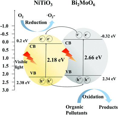 | ||
| Fig. 12 Schematic diagram of electron–hole pair separation and possible reaction mechanism of NiTiO3–Bi2MoO6 heterojunctions under visible light irradiation. | ||
4. Conclusions
In summary, NiTiO3–Bi2MoO6 heterojunctions have been successfully prepared by an electrospinning–calcination–solvothermal method. They are composed of NiTiO3 nanofibers which are coated with Bi2MoO6 nanoneedles. NiTiO3–Bi2MoO6 heterojunctions exhibit enhanced photocatalytic activity compared with NiTiO3 and Bi2MoO6 under visible light irradiation, due to the efficient separation of electron–hole pairs. In addition, the photocatalytic process is dominantly governed by ˙O2− and h+. Moreover, NiTiO3–Bi2MoO6 photocatalysts can mineralize organic pollutants with good stability and can be easily recycled which demonstrates their great potential for practical application in environmental purification.Conflicts of interest
There are no conflicts to declare.Acknowledgements
This work was financially supported by the National Natural Science Foundation of China (Grant No. 21477019), the Fundamental Research Funds for the Central Universities, and the DHU Distinguished Young Professor Program.References
- J. Liu, Y. Liu, N. Liu, Y. Han, X. Zhang, H. Huang, Y. Lifshitz, S. T. Lee, J. Zhong and Z. Kang, Science, 2015, 347, 970–974 CrossRef CAS PubMed.
- C. C. Wang, J. R. Li, X. L. Lv, Y. Q. Zhang and G. Guo, Energy Environ. Sci., 2014, 7, 2831–2867 CAS.
- E. M. Dias and C. Petit, J. Mater. Chem. A, 2015, 3, 22484–22506 CAS.
- M. R. Hoffmann, S. T. Martin, W. Choi and D. W. Bahnemann, Chem. Rev., 1995, 95, 69–96 CrossRef CAS.
- H. Wang, L. Zhang, Z. Chen, J. Hu, S. Li, Z. Wang, J. Liu and X. Wang, Chem. Soc. Rev., 2014, 43, 5234–5244 RSC.
- A. Kubacka, M. Fernández-García and G. Colón, Chem. Rev., 2012, 112, 1555–1614 CrossRef CAS PubMed.
- W. Wang, X. Chen, G. Liu, Z. Shen, D. Xia, P. K. Wong and C. Y. Jimmy, Appl. Catal., B, 2015, 176, 444–453 CrossRef.
- S. Li, K. Xu, S. Hu, W. Jiang, J. Zhang, J. Liu and L. Zhang, Appl. Surf. Sci., 2017, 397, 95–103 CrossRef CAS.
- L. S. Zhang, W. Z. Wang, L. Zhou and H. L. Xu, Small, 2007, 3, 1618–1625 CrossRef CAS PubMed.
- L. S. Zhang, W. Z. Wang, Z. G. Chen, L. Zhou, H. L. Xu and W. Zhu, J. Mater. Chem., 2007, 17, 2526–2532 RSC.
- J. Xia, J. Di, S. Yin, H. Xu, J. Zhang, Y. Xu, L. Xu, H. Li and M. Ji, RSC Adv., 2014, 4, 82–90 RSC.
- J. Di, J. Xia, M. Ji, H. Li, H. Xu, H. Li and R. Chen, Nanoscale, 2015, 7, 11433–11443 RSC.
- X. Shen, T. Zhang, P. Xu, L. Zhang, J. Liu and Z. Chen, Appl. Catal., B, 2017, 219, 425–431 CrossRef CAS.
- Y. Liu, X. Zhang, J. Wang and P. Yang, Phys. Chem. Chem. Phys., 2016, 18, 31513–31520 RSC.
- Y. Shiraishi, S. Kanazawa, Y. Sugano, D. Tsukamoto, H. Sakamoto, S. Ichikawa and T. Hirai, ACS Catal., 2014, 4, 774–780 CrossRef CAS.
- J. B. Bellam, M. A. Ruiz-Preciado, M. Edely, J. Szade, A. Jouanneaux and A. H. Kassiba, RSC Adv., 2015, 5, 10551–10559 RSC.
- Y. Qu, W. Zhou, Z. Ren, S. Du, X. Meng, G. Tian, K. Pan, G. Wang and H. Fu, J. Mater. Chem., 2012, 22, 16471–16476 RSC.
- M. Sadjadi, M. Mozaffari, M. Enhessari and K. Zare, Superlattices Microstruct., 2010, 47, 685–694 CrossRef CAS.
- P. Jing, W. Lan, Q. Su, M. Yu and E. Xie, Sci. Adv. Mater., 2014, 6, 434–440 CrossRef CAS.
- Q. Sun, K. Lv, Z. Zhang, M. Li and B. Li, Appl. Catal., B, 2015, 164, 420–427 CrossRef.
- Y. Li, K. Lv, W. Ho, F. Dong, X. Wu and Y. Xia, Appl. Catal., B, 2017, 202, 611–619 CrossRef CAS.
- B. Inceesungvorn, T. Teeranunpong, J. Nunkaew, S. Suntalelat and D. Tantraviwat, Catal. Commun., 2014, 54, 35–38 CrossRef CAS.
- Y. Qu, W. Zhou, L. Jiang and H. Fu, RSC Adv., 2013, 3, 18305–18310 RSC.
- H. Wang, X. Yuan, H. Wang, X. Chen, Z. Wu, L. Jiang, W. Xiong, Y. Zhang and G. Zeng, RSC Adv., 2015, 5, 95643–95648 RSC.
- Y. Zhang, J. Gu, M. Murugananthan and Y. Zhang, J. Alloys Compd., 2015, 630, 110–116 CrossRef CAS.
- Y. Tian, B. Chang, Z. Yang, B. Zhou, F. Xi and X. Dong, RSC Adv., 2014, 4, 4187–4193 RSC.
- D. Yue, D. Chen, Z. Wang, H. Ding, R. Zong and Y. Zhu, Phys. Chem. Chem. Phys., 2014, 16, 26314–26321 RSC.
- Y. Ma, Y. Jia, Z. Jiao, M. Yang, Y. Qi and Y. Bi, Chem. Commun., 2015, 51, 6655–6658 RSC.
- W. Dai, J. Yu, H. Xu, X. Hu, X. Luo, L. Yang and X. Tu, CrystEngComm, 2016, 18, 3472–3480 RSC.
- D. Chen, Q. Hao, Z. Wang, H. Ding and Y. Zhu, CrystEngComm, 2016, 18, 1976–1986 RSC.
- M. Zhang, C. Shao, J. Mu, Z. Zhang, Z. Guo, P. Zhang and Y. Liu, CrystEngComm, 2012, 14, 605–612 RSC.
- S. Li, L. Zhang, H. Wang, Z. Chen, J. Hu, K. Xu and J. Liu, Sci. Rep., 2014, 4, 3978 CrossRef PubMed.
- H. Zhao, L. Zhang, X. Gu, S. Li, B. Li, H. Wang, J. Yang and J. Liu, RSC Adv., 2015, 5, 10951–10959 RSC.
- S. Li, X. Shen, J. Liu and L. Zhang, Environ. Sci., 2017, 4, 1155–1167 CAS.
- Y. J. Lin, Y. H. Chang, W. D. Yang and B. S. Tsai, J. Non-Cryst. Solids, 2006, 352, 789–794 CrossRef CAS.
- C. Luo, D. Li, W. Wu, C. Yu, W. Li and C. Pan, Appl. Catal., B, 2015, 166, 217–223 CrossRef.
- Y. Wong, Y. Szeto, W. Cheung and G. McKay, J. Appl. Polym. Sci., 2004, 92, 1633–1645 CrossRef CAS.
- Y. Chen, G. Tian, Y. Shi, Y. Xiao and H. Fu, Appl. Catal., B, 2015, 164, 40–47 CrossRef CAS.
- G. Tian, Y. Chen, W. Zhou, K. Pan, Y. Dong, C. Tian and H. Fu, J. Mater. Chem., 2011, 21, 887–892 RSC.
Footnotes |
| † Electronic supplementary information (ESI) available. See DOI: 10.1039/c7nj03367b |
| ‡ These authors contributed equally to this work. |
| This journal is © The Royal Society of Chemistry and the Centre National de la Recherche Scientifique 2018 |

