
Activating basal plane in NiFe layered double hydroxide by Mn2+ doping for efficient and durable oxygen evolution reaction†
Daojin
Zhou
a,
Zhao
Cai
a,
Yin
Jia
b,
Xuya
Xiong
a,
Qixian
Xie
a,
Shiyuan
Wang
b,
Ying
Zhang
c,
Wen
Liu
 *a,
Haohong
Duan
*d and
Xiaoming
Sun
*ab
*a,
Haohong
Duan
*d and
Xiaoming
Sun
*ab
aState Key Laboratory of Chemical Resource Engineering, Beijing Advanced Innovation Center for Soft Matter Science and Engineering, Beijing University of Chemical Technology, Beijing, 100029, China. E-mail: wenliu@mail.buct.edu.cn; sunxm@mail.buct.edu.cn
bState Key Laboratory of Chemical Resource Engineering, College of Energy, Beijing Advanced Innovation Center for Soft Matter Science and Engineering, Beijing University of Chemical Technology, Beijing, 100029, China
cCollege of Chemical Engineering, China University of Petroleum (East China), Qingdao, Shandong Province 266580, China
dChemistry Research Laboratory, Department of Chemistry, University of Oxford, 12 Mansfield Road, Oxford, OX1 3TA, UK. E-mail: haohong.duan@chem.ox.ac.uk
First published on 27th June 2018
Abstract
Foreign metal ions with reducing ability were doped into NiFe layered double hydroxides (NiFe-LDHs) to activate the basal plane in NiFe-LDHs for oxygen evolution reaction (OER). Mn2+-Doped NiFe-LDH array electrode yields a low onset potential of 1.41 V and exhibits outstanding stability. The study herein illustrates a new dimension of electronic structure regulation and promises further optimization of highly efficient electrocatalysts.
Conceptual insightsAs benchmark electrocatalysts for oxygen evolution reaction (OER), NiFe layered double hydroxides (NiFe-LDHs) are known to comprise active edge sites, while the basal plane remains inert. Activating the basal plane could fully utilize the NiFe-LDHs materials, but it still remains a challenge. Herein, we report the activation of basal plane in NiFe-LDHs for OER by introducing foreign metal ions with weaker electronegativity to Ni and Fe. Theoretical result shows that the electron densities on Ni and Fe sites in basal plane were increased, making them new active sites for OER. Proper choice of introduced foreign metal ions yields a low onset potential of 1.41 V and fast current density growth (100 mA cm−2 at 230 mV overpotential) on a Mn2+-doped NiFe-LDH array electrode, which is among the most active OER electrocatalysts to date. This study illustrates a new dimension of electronic structure regulation and promises further optimization of high efficiency electrocatalysts. |
Faced with energy crisis from depletion of fossils, hydrogen production from water splitting has become the worldwide research focus.1–3 Oxygen evolution reaction (OER) is a key half-reaction in water splitting; however, the sluggish reaction kinetics has driven researchers to find optimal electrocatalysts.4–7 Among all existing catalysts, NiFe (oxy)hydroxides or NiFe layered double hydroxides (NiFe-LDHs) have been acknowledged as the most promising OER catalyst in alkaline conditions.8–13 Previous literature has demonstrated that metal sites located at step,14 edge and corner15 sites in heterogeneous catalysts with electron-rich structures are highly active. Boettcher et al. further suggested that the Fe in Ni/Fe (oxy)hydroxide located at edges or defects was responsible for the exceptional oxygen electrocatalytic activity, while basal plane Fe with electron-equilibrium structure and saturated coordination number was less active.16 Since basal plane constitutes majority of the bulk materials, activating the basal plane could lead to full utilization of the NiFe-LDH structures and further enhance the OER activity. A typical strategy to activate the basal plane of NiFe-LDH is based on tailoring of the surface electronic structure of metal sites in NiFe-LDH, as it has a profound effect on the deprotonating step and binding strength of LDH surface to the electrochemical reaction intermediate. For instance, the accumulation of negative charge on metal sites in LDH nanosheets induced by the formation of oxygen vacancies improved the OER performances through plasma treatment.17 Moreover, intercalating redox anions into the interlayer of NiFe-LDH could modify the electronic structure and contribute to the improved OER catalytic activity.18,19 In addition, converting hydroxides to sulfides20 or phosphides21,22 have also been demonstrated to be effective in enhancing the OER activity by tailoring the electron structure of the metal sites. However, the LDH treated by plasma or etching methods are vulnerable or fragile due to the ultrathin or defective structure, and the intercalated guest anions in LDH can possibly be substituted by hydroxyl groups in the electrolyte. As a result, more robust NiFe-LDH structures with electronic modification on basal plane23 are urgently required for further development of high performance OER electrocatalysts.
As a proof of concept, herein, we report that the surface electronic structure of basal plane could be modified by introducing Mn2+ with weaker electronegativity to Ni and Fe into NiFe-LDH matrix to further boost the OER performance. Based on density functional theory (DFT)+U computational results, we studied the charge compensation phenomenon between the in-plane metal sites and the Gibbs free energy evolution in the process of OER. The electron density of Ni and Fe increased after Mn2+ doping, as-revealed by both DFT simulation and X-ray photoelectron spectroscopy (XPS). The effect of introducing foreign metal ions reduced the onset potential of Mn-doped NiFe-LDH to 1.41 V (vs. reversible hydrogen electrode) and it only required 230 mV overpotential to reach a current density of 100 mA cm−2. The formation of electron-rich structure of both Ni and Fe sites benefits the deprotonating step and lowers the overpotential of NiFe-LDH for OER. The effect of introducing foreign metal ions on OER activity was further verified by introducing Fe2+ or Zn2+, and hence represents a general strategy to enhance the total activity of NiFe-LDHs OER catalyst.
The (110) surface was taken into consideration in calculations as this surface corresponds to the edge of LDH with dominant active sites. To simulate the Mn2+-doped NiFe-LDH, the Ni2+ atoms were manually replaced by Mn2+ atoms (Fig. 1A and B). First, based on the DFT+U calculation, we studied the electron density evolution of Ni and Fe sites in NiFe-LDH before and after Mn2+ ion doping. Fig. 1C and D show the electron density distribution maps of Ni/Fe sites in NiFe-LDHs and their doped counterparts, respectively, by Bader charge after energy optimization. The electron density of both Ni2+ and Fe3+ increased after Mn2+ doping compared with that in pristine NiFe-LDH (prior to doping: Ni2+ (8.92), Fe3+ (6.72); after doping: Ni2+ (8.96), Fe3+ (6.83)). The electron density enhancement revealed by these calculations proves that there is electron transfer between metal sites in the matrix of doped NiFe-LDH aroused by the reducing ability of Mn2+ with weak electronegativity. Considering that the electronic structure of Ni2+ and Fe3+ in pristine NiFe-LDH is in a dynamic equilibrium state, the substitution of Ni2+ by Mn2+ with higher reducing ability and weaker electronegativity would break this equilibrium state and leave the surrounding Ni2+ and Fe3+ with an electron-rich structure.24 This in-plane charge transfer and recompensation scheme can well explain the electron density evolution of metal sites in the Mn2+-doped NiFe-LDHs, which also indicates that introducing Mn2+ in LDHs matrix is effective for surface electronic structure modification of the Ni2+ and Fe3+ sites.
 | ||
| Fig. 1 Schematic structure and electron density evolution based on DFT calculation. Schematic structure of (A) pristine NiFe-LDH, (B) Mn2+-doped NiFe-LDH. Electronic structure of Ni and Fe sites in (C) pristine NiFe-LDH, (D) Mn2+-doped NiFe-LDH. | ||
To confirm the prediction from the computational results, we prepared pristine and Mn2+-doped NiFe-LDH arrays and tested their OER activity. Pristine NiFe-LDH array was prepared by a typical hydrothermal process, as illustrated in experimental section. To prepare Mn2+-doped NiFe-LDH array, an optimal amount of Ni2+ precursor was substituted by Mn2+ precursor. To prevent the oxidation of Mn2+ by oxygen, N2 was bubbled in the mixture solution to remove the dissolved oxygen. The hydrothermal preparation of Mn2+-doped NiFe-LDH array was carried out in a vacuum oven.
To confirm that the electronic structure of Ni and Fe sites were modified by introducing Mn2+, XPS was applied to characterize the binding energies of Ni, Fe and O sites in pristine and doped NiFe-LDH and the valence states of Mn precursor and Mn in doped NiFe-LDH. As clearly illustrated in Fig. 2A and B, the negative shift in both Ni 2p and Fe 2p binding energy peaks indicates the lower valence states and electron-rich structure of Ni2+ and Fe3+ sites, illustrating the electron transfer from Mn2+ to Ni2+ and Fe3+ sites in the doped NiFe-LDH, which is in good agreement with the computational results. The low intensity of Ni binding peak at ∼853.6 eV could be attributed to the Ni foam as impurity, which is possibly induced by the ultrasonication process. As shown in Fig. 2C, the binding energy evolution of O sites in NiFe-LDH before and after doping was compared. The typical metal–oxygen bond was ascribed by the peak located at 529.8 eV, and can be observed as the main component in NiFe-LDHs before doping.25 The binding energy peak at 531.8 eV with higher intensity is shown in the XPS mapping of Mn2+-doped NiFe-LDH after doping, which could be assigned to the growing concentration of oxygen vacancies.26,27 Accompanying the formation of electron-rich structure of both Ni2+ and Fe3+ sites, fewer amount of –OH is required to coordinate with Ni and Fe sites, leading to more oxygen vacancies generated in the hydroxides matrix.17 Oxygen vacancies in the Mn2+-doped NiFe-LDH array could significantly increase the uptake of water molecules on the catalysts’ surface and further accelerate the reaction between –OH with the active sites,28 thus boosting the OER catalytic kinetics.
 | ||
| Fig. 2 XPS data of different sites in pristine and Mn2+-doped NiFe-LDH. High resolution XPS profiles of (A) Ni sites, (B) Fe sites, and (C) O sites in pristine and Mn2+-doped NiFe-LDH. (D) Comparison between Mn precursor and Mn in doped LDH, indicating the precursor is Mn2+ while Mn in doped NiFe-LDH is Mn4+. | ||
The valence states of Mn2+ precursor and Mn species in doped NiFe-LDH are revealed in Fig. 2D. Prior to doping, the valence state of Mn precursor is +2 (641.7 eV). After doping, the valence state of Mn increased from +2 to +4 (642.7 eV), suggesting that an electron transferred from Mn2+ atoms to the surrounding Ni2+ and Fe3+ sites in LDH.
In order to investigate the impact of metal ions’ electronegativity on the surface electronic structure, we used Mn4+ rather than Mn2+ as the precursor ion and doped it into the NiFe-LDH array. The binding energies of Ni, Fe and Mn in the Mn4+-doped NiFe-LDH array are shown in Fig. S1 (ESI†). Although both the valence states of Mn in the two as-prepared products are Mn4+, binding energies of Ni and Fe sites are significantly different. The electronic structures of Ni and Fe sites are not significantly influenced by introducing Mn4+ precursor, while the use of Mn2+ precursor modifies Ni and Fe sites into electron-rich structures. This result suggests that heteroatoms with weaker electronegativity have a more significant contribution towards electronic structure modification.
The X-ray diffraction (XRD) results (Fig. 3A) showed the typical (003), (006) and (012) diffraction peaks for pristine and Mn2+-doped NiFe-LDH. The crystal structure merely changed before and after doping, while the slightly weaker crystallinity of Mn2+-doped NiFe-LDH array can be explained by the long-range disorder and matrix distortion caused by substitution of Ni2+ (r ≈ 0.069 nm) by Mn4+ (r ≈ 0.053 nm) in the doped NiFe-LDH array. The in-plane distortion can hardly be observed by XRD as the (110) and (113) peaks are relatively weak. The lattice distances along the (110) facet measured by HRTEM (Fig. 3C and E) negligibly changed. Fig. 3F–I, reveal the element mappings of Ni, Fe and Mn in Mn2+-doped NiFe-LDH, showing homogenous distribution of Ni, Fe and Mn throughout the nanosheets of Mn2+-doped NiFe-LDH. The ratio of Ni![[thin space (1/6-em)]](https://www.rsc.org/images/entities/char_2009.gif) :Fe:Mn is about 56:36:8, which is very close to the ratio of the amount of precursors used for our materials’ design and further proved the successful synthesis of the doped catalyst material.
:Fe:Mn is about 56:36:8, which is very close to the ratio of the amount of precursors used for our materials’ design and further proved the successful synthesis of the doped catalyst material.
 | ||
| Fig. 3 Structure and morphology of pristine and Mn2+-doped NiFe-LDH array. (A) XRD of pristine and Mn2+-doped NiFe-LDH arrays. (B and C) SEM and HRTEM images of NiFe-LDHs array. (D and E) SEM and HRTEM images of Mn2+-doped NiFe-LDHs array. The bar in scanning electron microscopy (SEM) represents 500 nm, and bar in transmission electron microscopy (TEM) stands for 5 nm; (F–I) elemental mapping of Ni, Fe and Mn in Mn2+-doped NiFe-LDH by STEM-EDX (the scale bar in (F–I) stands for 100 nm). | ||
Electrochemical performances of all the samples were measured and shown in Fig. 4, demonstrating the effect of electronic structure modification of basal plane on the electrocatalytic activity of Mn2+ doped NiFe-LDH array. As shown in Fig. 4A, by a reverse extension line through CV, onset potential of Mn2+-doped NiFe-LDH was as low as 1.41 V (vs. RHE), corresponding to a record low overpotential of 180 mV. Also, only 190 mV and 230 mV overpotentials were required for Mn2+-doped NiFe-LDH to reach the current density of 10 mA cm−2 and 100 mA cm−2, respectively, after iR-correction, while pristine NiFe-LDH required 335 mV overpotential to reach the current density of 100 mA cm−2. It is noteworthy that to the best of our knowledge, the Mn2+-doped NiFe-LDH shows the best performance for NiFe hydroxides as OER catalysts and is also comparable to the state-of-the-art OER catalysts in alkaline electrolyte (Table S1, ESI†).8,29,30
 | ||
| Fig. 4 OER performance and comparison. (A) Cyclic voltammetry (CV), (B) Tafel slops, and (C) EIS of pristine NiFe-LDH, Mn2+-doped NiFe-LDH and RuO2. (D) ECSA of pristine NiFe-LDH and Mn2+-doped NiFe-LDH. (E) Stability of Mn2+-doped NiFe-LDH demonstrated by chronopotentiometry measurement (i–t curves). | ||
As shown in Fig. 4A, the redox peaks prior to OER in different samples were studied. The evolution of these peaks can also reflect the doping effect of Mn2+ into the NiFe-LDH matrix. Oxidation peaks of metal sites in Mn2+-doped NiFe-LDH prior to the OER process can be assigned to two species, indicating the transformation from Ni(OH)2 to NiOOH.31–33 The first peak, which appears at around 1.34 V, can be attributed to the oxidation of Ni2+ sites located closely to the reducing Mn2+ with higher electron density, termed as β-NiOOH (denoted as ①), while the following peak corresponds to the oxidation of Ni sites located far away from the reducing Mn2+, termed as γ-NiOOH (denoted as ②) at higher potential.34 β-NiOOH (Ni oxidized state is lower than +3) is more active than γ-NiOOH (Ni oxidized state is around +3.6). However, only one oxidation peak of γ-NiOOH can be detected at around 1.47 V in the pristine NiFe-LDH as the unaffected Ni sites can be only oxidized at higher potential. The shift in the redox peak in LDHs again confirmed the charge compensation phenomenon in the basal plane of Mn2+-doped NiFe-LDH. Herein, the doping of Mn2+ with strong reducing ability leads to the electron-rich structure of both Ni2+ and Fe3+ sites (Fig. 2), which stabilizes the lower oxidation state of Ni and promotes the formation of active β-NiOOH. In OER, the working valence state of Fe will be finally higher than 3+,30 so the OER performance on catalysts would be enhanced if the oxidation of metal sites can easily occur. The electron-rich structure of Ni in Mn2+-doped NiFe-LDH results in its early oxidation to higher valence states, and hence promotes the water oxidation performances.35 The Tafel slopes in Fig. 4B reveals that the kinetics of water oxidation on the surface of LDH catalysts changed owing to the basal-plane electronic structural modification. Compared with that of pristine NiFe-LDH, the Tafel slope of Mn2+-doped NiFe-LDH changed from ∼75 mV dec−1 to ∼68 mV dec−1, indicating the enhanced kinetics of adsorption of –OH on active sites.
As shown in Fig. 4C, the EIS of Mn4+-doped NiFe-LDH array had a smaller semi-circle compared with that of pristine NiFe-LDH, indicating the lower charge transfer resistance.36 Interestingly, we notice that charge transfer resistance can be reduced in Mn2+-doped NiFe-LDH both from Mn2+ and Mn4+ precursors. As shown in Fig. S2 (ESI†), the decrease in charge transfer resistance verified that Mn4+ can also boost the conductivity of doped NiFe-LDH. The total density of states (TDOS) was calculated and shown in Fig. S3 (ESI†), confirming a narrower band gap of Mn-doped NiFe-LDHs, which well agreed with the EIS measurements. Beyond traditional doping methods that only improve the conductivity,37 in this study, in-plane charge compensation caused by Mn2+ to Mn4+ simultaneously tunes the electronic structure of the surrounding Ni2+ and Fe3+ sites, leading to activation of basal plane sites and further OER performance enhancement of Mn2+-doped NiFe-LDH array.
To further verify that the basal plane of NiFe-LDH is activated, electrochemical active surface area (ECSA) of both pristine and Mn2+-doped NiFe-LDH array (potential range: 0–0.15 V, scan rate: 1–5 mV s−1) was tested and illustrated in Fig. 4D and Fig. S4 (ESI†). As can be clearly seen from the figures, ECSA of NiFe-LDH increases from 4.16 mF cm−2 to 6.08 mF cm−2 after doping with Mn2+ precursor, demonstrating that the number of active sites increases as the electron-rich structure of Ni2+ and Fe3+ sites are formed. As shown in Fig. S5 (ESI†), the ECSA-normalized LSV of pristine and doped NiFe-LDH showed enhanced intrinsic activity of Mn2+-doped NiFe-LDH. These results proved that the basal-plane metal sites have been activated and agreed with abovementioned evidences. We then summarized the turnover frequency (TOF) of pristine and Mn2+-doped NiFe-LDH at overpotential of 300 mV in Table S2 (ESI†). The number of surface sites is inferred from the ECSA. The TOF of Mn-doped NiFe-LDH is 0.30 s−1, which is higher than that of pristine NiFe-LDH (0.11 s−1). The high TOF of Mn2+-doped NiFe-LDH indicates higher catalytic activity compared with that of pristine NiFe-LDH.
The stability test of Mn2+-doped NiFe-LDH is shown in Fig. 4E and Fig. S6 (ESI†). The i–t curve of Mn2+-doped NiFe-LDH shows a mere 6% current density decay after 40 h continuous water electrolysis, further confirming the working stability of our electrocatalyst. As shown in Fig. S6 (ESI†), no significant difference can be observed in both onset potential and current density of Mn2+-doped NiFe-LDH after 750 CV cycles. Also, the electronic structures of Ni2+ and Fe3+ after 750 CV cycles results in negligible changes in the corresponding XPS profiles, as shown in Fig. S7 (ESI†).
To rationalize the improved water oxidation performance of Mn2+-doped NiFe-LDH, the ΔG evolution of pristine and doped NiFe-LDH was studied and shown in Fig. 5. According to the discussion above, Fe3+ without oxygen vacancy (electron-equilibrium structure)/with oxygen vacancy (electron-rich structure) oxygen vacancy in (110) plane is selected as the active site. The difference between ΔG of Mn2+-doped NiFe-LDH and pristine NiFe-LDH could reflect the adsorption and desorption ability of reaction intermediate on the catalyst surface, which have been influenced by the electronic structure of the metal sites. As shown in Fig. 5, the energy barrier for the deprotonating step of Mn2+-doped NiFe-LDH is significantly lower than that of pristine NiFe-LDH, with the Gibbs free energy of the first step changing from 1.31 eV to 1.25 eV, suggesting that water and –OH adsorption to electron-rich metal sites in Mn2+-doped NiFe-LDH is promoted. The second step involves deprotonation of OH* and adsorption of O*, in which the ΔG is 2.13 eV and the overpotential is 0.901 eV. This is the potential determining step (PDS) for pristine NiFe-LDH. In Mn2+-doped NiFe-LDH, the ΔG of the second step is 1.72 eV and overpotential is 0.49 V, which are significantly lower than those of pristine NiFe-LDH. Following the Sabatier principle,38 the modified catalyst's surface has the optimal adsorption and desorption energy to the reaction intermediate; thus, the water oxidation catalytic efficiency of Mn2+-doped NiFe-LDH is enhanced. Computational results confirm that the electron-rich Ni2+ and Fe3+ sites in Mn2+-doped NiFe-LDH have a positive impact on the water oxidation catalytic activity.
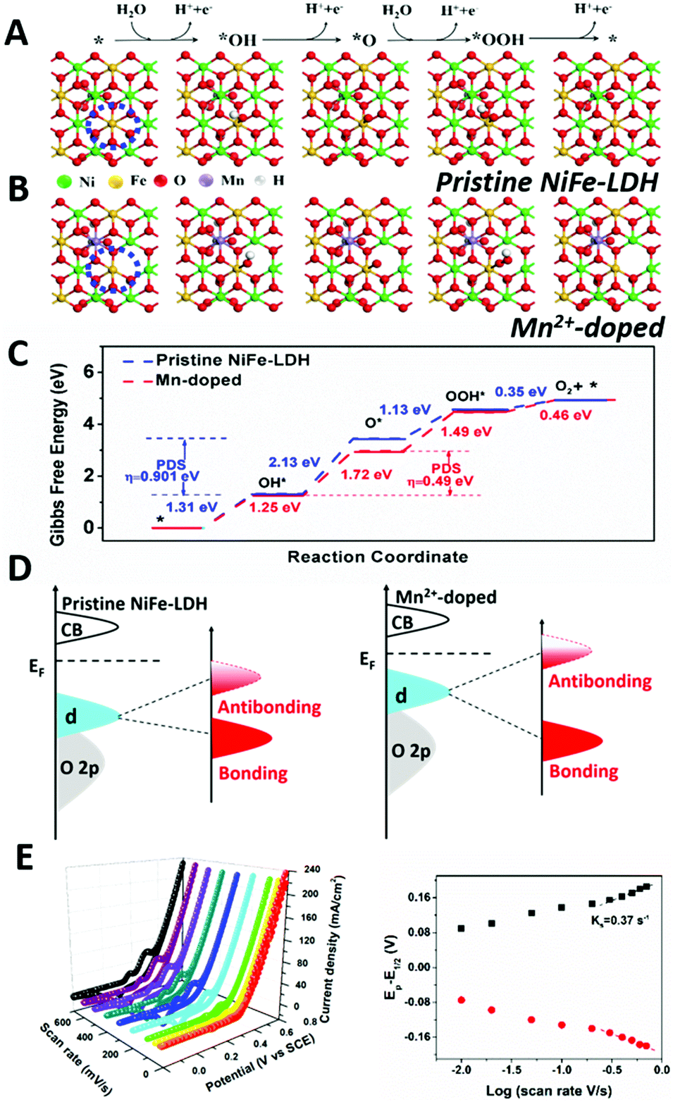 | ||
| Fig. 5 Proposed four-electron mechanism of oxygen evolution reaction and Gibbs free energy evolution based on DFT+U calculation. (A) Pristine NiFe-LDH, (B) Mn2+-doped NiFe-LDH. The top is the brief 4e-mechanism of OER. In-plane Fe in blue circle is selected as active site in LDH samples. (C) Gibbs free energy diagram for the four steps of OER on pristine NiFe-LDHs (blue line) and Mn2+-doped NiFe-LDHs (red line). The second step is the potential determining step and η stands for over-potential. The lower activation Gibbs free energy of Mn2+-doped NiFe-LDHs predicts more favorable OER kinetics. (D) Schematic illustration of d band theory based on the effect of Mn2+ doping on NiFe-LDH. (E) Laviron analysis of Mn2+-doped NiFe-LDH based on different scan rates. | ||
As shown in Fig. 5D, we propose the evolution of binding strength of electrochemical reaction intermediate on the surface of pristine NiFe-LDH and Mn2+-doped sample based on CV data and d band theory. Basically, NiFe-LDH has weak binding strength towards –OH during electrochemical reaction, which hinders its catalytic activity. After Mn2+ doping, the binding strength of Mn2+-doped NiFe-LDH to –OH is enhanced (earlier oxidation peak of Ni in Fig. 4A and 1.25 eV for the adsorption of –OH to active sites in Fig. 5C), which can be attributed to the upshift in the antibonding states relative to EF (Fermi level). Accompanying with the upshift of the antibonding state, the d band center will also get close to EF with a narrower bandgap, which is in line with our calculation results in Fig. S3 (ESI†). We then compared the binding strength of –OH on pristine NiFe-LDH and Mn2+-doped sample based on the Laviron equation.39 As shown in Fig. 5E, the larger ks (redox constant) of Mn2+-doped NiFe-LDH compared with that of pristine NiFe-LDH (Fig. S8, ESI†) indicates the stronger binding strength of Mn2+-doped sample to the –OH intermediate.
The doped heteroatoms with strong reducing ability and weak electronegativity in hydroxide matrix make two contributions. On one hand, by inducing electron transfer from Mn2+ to Ni2+ and to Fe3+, the electronic structures of Ni2+ and Fe3+ in the basal plane were modified from electron-equilibrium to electron-rich status. As a result, the activated basal plane facilitates deprotonating step, which is mainly responsible for the enhanced electrochemical catalytic performances.40 On the other hand, the high valence states of doped heteroatoms in catalyst would facilitate the electron conductivity in the process of water oxidation, further boosting the current density growth of the doped NiFe-LDH array.
To further correlate the enhanced water oxidation performance with the electron-rich structure of Ni2+ and Fe3+ sites in LDH, the doping effect of Fe2+ (with high reducing ability/weak electronegativity) and Zn2+ (with no reducing ability) on the water oxidation catalytic performance of NiFe-LDH array was further studied. The structure and morphology of Fe2+ or Zn2+-doped NiFe-LDH are revealed in Fig. S9 and S10 (ESI†), and the electronic structure evolution of Ni2+ and Fe3+ sites in doped NiFe-LDH is shown in Fig. S11 (ESI†). As predicted, the electron-rich structure of Ni2+ and Fe3+ sites were found in Fe2+-doped NiFe-LDH due to the reducing ability of Fe2+ ion, while there is no significant electron-structure change in Ni2+ and Fe3+ sites in Zn2+-doped NiFe-LDH. As shown in Fig. S12 (ESI†), the OER catalytic performances confirmed the positive effect of Fe2+ doping and negative effect of Zn2+ doping, which are mainly aroused by electron-structure differences in Ni2+ and Fe3+ sites in Fe2+-doped NiFe-LDH and Zn2+-doped NiFe-LDH. Another control experiment was conducted to study whether the doping of Mn2+ had a positive effect on colloidal NiFe-LDH. As shown in Fig. S13 (ESI†), the colloidal Mn2+-doped showed superior OER activity to that of pristine NiFe-LDH.
In summary, we have developed an effective approach to activate the basal plane of NiFe-LDH for enhanced OER activity, by introducing foreign metal ions with high reducing ability/weak electronegativity. Computational and experimental results show the electron transfer from Mn2+ with strong reducing ability to surrounding Ni2+ and Fe3+ in the hydroxide matrix, leading to Ni2+ and Fe3+ with electron-rich structures, which facilitates the deprotonating step and significantly improvement its water oxidation performances. NiFe-LDH doped by Mn2+ precursor shows the onset potential as low as 1.41 V (vs. RHE) and fast current density growth, manifesting the best OER catalyst in alkaline electrolyte. To facilitate the correlation between theory and experiments, this study was restricted to doping of limited number of foreign metal ions, namely, Mn2+, Fe2+ and Zn2+ with distinct electronic features. However, the introduction of foreign metal ions could be a general strategy to activate the basal plane, and higher OER intrinsic activity could be envisaged if a more proper foreign metal ion is found. More importantly, this study shows the capability to regulate the intrinsic properties of electrode materials beyond NiFe-LDHs towards much broader energy related applications.
Conflicts of interest
There are no conflicts to declare.Acknowledgements
This study was financially supported by the National Natural Science Foundation of China, the Program for Changjiang Scholars and Innovative Research Team in the University (IRT1205), the Fundamental Research Funds for the Central Universities, the Long-Term Subsidy Mechanism from the Ministry of Finance and the Ministry of Education of PRC and the National Key Research and Development Project (2016YFF0204402).Notes and references
- M. Gong and H. Dai, Nano Res., 2014, 8, 23–39 CrossRef.
- D. A. Kuznetsov, B. Han, Y. Yu, R. R. Rao, J. Hwang, Y. Román-Leshkov and Y. Shao-Horn, Joule, 2018, 2, 225–244 CrossRef.
- N. Wu, J. Low, T. Liu, J. Yu and S. Cao, Appl. Surf. Sci., 2017, 413, 35–40 CrossRef.
- F. Dionigi and P. Strasser, Adv. Energy Mater., 2016, 6, 1600621 CrossRef.
- P. Kuang, B. Zhu, Y. Li, H. Liu, J. Yu and K. Fan, Nanoscale Horiz., 2018, 3, 317–326 RSC.
- Y. Hou, M. R. Lohe, J. Zhang, S. Liu, X. Zhuang and X. Feng, Energy Environ. Sci., 2016, 9, 478–483 RSC.
- X. Lv, X. Xiao, M. Cao, Y. Bu, C. Wang, M. Wang and Y. Shen, Appl. Surf. Sci., 2018, 439, 1065–1071 CrossRef.
- C. G. Morales-Guio, L. Liardet and X. Hu, J. Am. Chem. Soc., 2016, 138, 8946–8957 CrossRef PubMed.
- K. Fan, H. Chen, Y. Ji, H. Huang, P. M. Claesson, Q. Daniel, B. Philippe, H. Rensmo, F. Li, Y. Luo and L. Sun, Nat. Commun., 2016, 7, 11981 CrossRef PubMed.
- D. Liu, S. Ding, C. Wu, W. Gan, C. Wang, D. Cao, Z. ur Rehman, Y. Sang, S. Chen and X. Zheng, J. Mater. Chem. A, 2018, 6, 6840–6846 RSC.
- Q. He, H. Xie, Z. ur Rehman, C. Wang, P. Wan, H. Jiang, W. Chu and L. Song, ACS Energy Lett., 2018, 3, 861–868 CrossRef.
- Q. He, Y. Wan, H. Jiang, Z. Pan, C. Wu, M. Wang, X. Wu, B. Ye, P. M. Ajayan and L. Song, ACS Energy Lett., 2018, 3, 1373–1380 CrossRef.
- R. Chen, G. Sun, C. Yang, L. Zhang, J. Miao, H. Tao, H. Yang, J. Chen, P. Chen and B. Liu, Nanoscale Horiz., 2016, 1, 156–160 RSC.
- J. H. K. Pfisterer, Y. Liang, O. Schneider and A. S. Bandarenka, Nature, 2017, 549, 74–77 CrossRef PubMed.
- F. Calle-Vallejo, J. Tymoczko, V. Colic, Q. H. Vu, M. D. Pohl, K. Morgenstern, D. Loffreda, P. Sautet, W. Schuhmann and A. S. Bandarenka, Science, 2015, 350, 185–189 CrossRef PubMed.
- M. B. Stevens, C. D. Trang, L. J. Enman, J. Deng and S. W. Boettcher, J. Am. Chem. Soc., 2017, 139, 11361–11364 CrossRef PubMed.
- L. Xu, Q. Jiang, Z. Xiao, X. Li, J. Huo, S. Wang and L. Dai, Angew. Chem., Int. Ed., 2016, 128, 5363–5367 CrossRef.
- M. Luo, Z. Cai, C. Wang, Y. Bi, L. Qian, Y. Hao, L. Li, Y. Kuang, Y. Li and X. Lei, Nano Res., 2017, 10, 1732–1739 CrossRef.
- D. Zhou, Z. Cai, Y. Bi, W. Tian, M. Luo, Q. Zhang, Q. Xie, J. Wang, Y. Li and Y. Kuang, Nano Res., 2018, 11, 1358–1368 CrossRef.
- J. Yu, G. Cheng and W. Luo, J. Mater. Chem. A, 2017, 5, 15838–15844 RSC.
- Y. Li, H. Zhang, M. Jiang, Q. Zhang, P. He and X. Sun, Adv. Funct. Mater., 2017, 27, 1702513 CrossRef.
- Y. Li and C. Zhao, ACS Catal., 2017, 7, 2535–2541 CrossRef.
- H. Xu, B. Wang, C. Shan, P. Xi, W. Liu and Y. Tang, ACS Appl. Mater. Interfaces, 2018, 10, 6336–6345 CrossRef PubMed.
- K. Li, M. Li and D. Xue, J. Phys. Chem. A, 2012, 116, 4192–4198 CrossRef PubMed.
- I. S. Cho, M. Logar, C. H. Lee, L. Cai, F. B. Prinz and X. Zheng, Nano Lett., 2014, 14, 24–31 CrossRef PubMed.
- S. A. Ansari, M. M. Khan, S. Kalathil, A. Nisar, J. Lee and M. H. Cho, Nanoscale, 2013, 5, 9238–9246 RSC.
- Z. Cai, Y. Bi, E. Hu, W. Liu, N. Dwarica, Y. Tian, X. Li, Y. Kuang, Y. Li, X.-Q. Yang, H. Wang and X. Sun, Adv. Energy Mater., 2018, 8, 1701694 CrossRef.
- B. Han, K. A. Stoerzinger, V. Tileli, A. D. Gamalski, E. A. Stach and Y. Shao-Horn, Nat. Mater., 2017, 16, 121–126 CrossRef PubMed.
- Y. Zhao, X. Jia, G. Chen, L. Shang, G. I. Waterhouse, L.-Z. Wu, C.-H. Tung, D. O’Hare and T. Zhang, J. Am. Chem. Soc., 2016, 138, 6517–6524 CrossRef PubMed.
- J. Y. Chen, L. Dang, H. Liang, W. Bi, J. B. Gerken, S. Jin, E. E. Alp and S. S. Stahl, J. Am. Chem. Soc., 2015, 137, 15090–15093 CrossRef PubMed.
- Y.-F. Li and A. Selloni, ACS Catal., 2014, 4, 1148–1153 CrossRef.
- R. D. Smith and C. P. Berlinguette, J. Am. Chem. Soc., 2016, 138, 1561–1567 CrossRef PubMed.
- M. Risch, F. Ringleb, M. Kohlhoff, P. Bogdanoff, P. Chernev, I. Zaharieva and H. Dau, Energy Environ. Sci., 2015, 8, 661–674 RSC.
- M. W. Louie and A. T. Bell, J. Am. Chem. Soc., 2013, 135, 12329–12337 CrossRef PubMed.
- Y. Xin, X. Kan, L. Y. Gan and Z. Zhang, ACS Nano, 2017, 11, 10303–10312 CrossRef PubMed.
- C. Zhang, M. Shao, L. Zhou, Z. Li, K. Xiao and M. Wei, ACS Appl. Mater. Interfaces, 2016, 8, 33697–33703 CrossRef PubMed.
- Z. Lu, L. Qian, Y. Tian, Y. Li, X. Sun and X. Duan, Chem. Commun., 2016, 52, 908–911 RSC.
- J. Lebreton, R. Sabatier, G. Banco and A.-M. Bacou, Applied multivariate analysis in SAR and environmental studies, Springer, 1991, pp. 85–114 Search PubMed.
- E. Laviron, J. Electroanal. Chem. Interfacial Electrochem., 1979, 101, 19–28 CrossRef.
- Y. Yang, L. Dang, M. Shearer, H. Sheng, W. Li, J. Chen, P. Xiao, Y. Zhang, R. Hamers and S. Jin, Adv. Energy Mater., 2018, 1703189 CrossRef.
Footnote |
| † Electronic supplementary information (ESI) available: SEM, XRD, XPS, polarization curves, stability test, AC impedance spectra. See DOI: 10.1039/c8nh00121a |
| This journal is © The Royal Society of Chemistry 2018 |