
Pseudocapacitance contribution in boron-doped graphite sheets for anion storage enables high-performance sodium-ion capacitors†
Feng
Yu‡
 b,
Zaichun
Liu‡
c,
Renwu
Zhou‡
b,
Deming
Tan
a,
Hongxia
Wang
*b and
Faxing
Wang
*a
b,
Zaichun
Liu‡
c,
Renwu
Zhou‡
b,
Deming
Tan
a,
Hongxia
Wang
*b and
Faxing
Wang
*a
aDepartment of Chemistry and Food Chemistry, Technische Universität Dresden, Dresden 01062, Germany. E-mail: faxing.wang@tu-dresden.de
bSchool of Chemistry, Physics and Mechanical Engineering, Science and Engineering Faculty, Queensland University of Technology, Brisbane, QLD 4001, Australia. E-mail: hx.wang@qut.edu.au
cSchool of Energy Science and Engineering, and Institute for Advanced Materials, Nanjing Tech University, Nanjing, China
First published on 23rd March 2018
Abstract
Research on metal-ion hybrid capacitors is emerging as one of the hottest topics in energy storage fields because of their combination of high power and energy densities. To improve the sluggish faradaic reaction in traditional electrode materials for metal-ion hybrid capacitors, intercalation pseudocapacitive materials have been developed as attractive candidates. However, all the previously reported pseudocapacitances in intercalation/deintercalation reactions are based on cations (Li+, Na+, Zn2+etc.). In this work, we demonstrated the high pseudocapacitance contribution in boron-doped graphite (BG) sheets by taking advantage of anion storage. The BG electrode can reversibly store anions (PF6−) through both a surface-controlled pseudocapacitive reaction and a diffusion-limited intercalation/deintercalation reaction. The fabricated Na-ion hybrid capacitor with a BG cathode exhibits superior electrochemical performance. Density functional theory (DFT) calculation reveals that B-doping can significantly reduce the PF6− diffusion energy barrier in the graphite layers.
Conceptual insightsElectrode materials with intercalation pseudocapacitances show great promise in achieving both high energy density and high power density, perfectly fulfilling the rigorous requirements of rechargeable batteries and electrochemical capacitors. Intercalation pseudocapacitance is based on the intercalation/de-intercalation of cations in the bulk of electrode materials, but its kinetics are based on a surface-limited redox reaction instead of a diffusion-limited one. Different from the traditional materials for metal-ion batteries, intercalation pseudocapacitive materials enable charging and discharging processes within the order of minutes or even seconds, which can provide both fast rate capability and high specific capacity. Currently, all the previously reported pseudocapacitive contributions in intercalation/deintercalation reactions are based on various cations (Li+, Na+, Zn2+etc.). In this work, we demonstrate that boron-doped graphite sheets can reversibly store anions (PF6−) through both a surface-controlled pseudocapacitive reaction and a diffusion-limited intercalation/deintercalation reaction. A Na-ion hybrid capacitor is fabricated with BG as the cathode and hollow carbon as the anode. The highly pseudocapacitive contribution in the BG electrode for anion storage enables the assembled Na-ion hybrid capacitor to exhibit an exceptionally high energy density and power density as well as a stable cycle life. This work will benefit the development of pseudocapacitive electrode materials towards the applications of high-rate electrochemical energy storage devices. |
Electrochemical capacitors and Li-ion batteries are the two most important existing energy storage systems for portable electronic devices and electric vehicles. Li-ion batteries deliver a high energy density because of the higher redox potential associated with the Faradaic charge storage mechanism, but suffer from a low power density owing to the sluggish kinetics of the Faradaic reaction in the bulk of the electrode. Due to the surface charge storage mechanism, electrochemical capacitors show a high power density and long cycle life, but display a low energy density (only 5–20 W h kg−1).1 In this area, to meet the requirements of both high energy and power densities, the concept of Li-ion hybrid capacitors was introduced in 2001, which use Faradaic battery-type anodes and electric-double-layer capacitor (EDLC) type carbonaceous cathodes.2 The charge storage mechanism of Li-ion hybrid capacitors is based on reversible anion adsorption/desorption onto/from the surface of the cathode and Li-ion reversible redox reactions (intercalating, conversion, and alloying) with the bulk of the anode simultaneously. Now it is generally accepted that the Li-ion hybrid capacitor is a device employing Li-ions and anions as the positive and negative charge carriers, respectively, in non-aqueous electrolytes.3 In the past decade, Li-ion hybrid capacitors have been intensively investigated,3–8 which normally display higher energy densities than electrochemical capacitors and higher power capabilities than Li-ion batteries. Thus Li-ion hybrid capacitors are expected to bridge the gap between Li-ion batteries and electrochemical capacitors. However, when considering the increasing demand for raw materials and the price of lithium resources, the most appealing and sustainable alternative is to replace lithium with sodium to build Na-ion hybrid capacitors, which was achieved in 2012.9 Over the past five years, various Na-ion hybrid capacitors have been explored with reasonable energy and power densities, which are regarded as new a generation of advanced electrochemical energy storage technologies.10–13 Similar to Li-ion hybrid capacitors, all the reported Na-ion hybrid capacitors store charge by surface anion adsorption/desorption onto/from the cathode and Na-ion redox reactions (such as intercalation/deintercalation, conversion and alloying) on the anode. However, the sluggish kinetics of Na-ion redox reactions in the anodes due to the larger ionic radii (0.98 Å) severely affects the electrochemical performance of Na-ion hybrid capacitors. Thus, developing high-performance Na-ion hybrid capacitors is particularly significant for the development of next-generation electrochemical energy storage devices.
In the early reported metal (Li or Na)-ion hybrid capacitors,10 the used anodes usually undergo metal ion insertion/extraction (Faradaic) reactions with diffusion-limited processes. Since the kinetics of a diffusion-limited reaction is more sluggish than that of physical adsorption/desorption of electrolyte ions, the fabricated metal-ion hybrid capacitors still have insufficient power densities, which is against the basics of electrochemical capacitors. To overcome the diffusion-limited drawback, several research efforts have been undertaken to realize a ‘real’ insertion behaviour with rapid metal ion storage kinetics, which is named as ‘intercalation pseudocapacitance’.14–19 As a new type of charge storage mechanism, intercalation pseudocapacitance is based on the intercalation/de-intercalation of cations in the bulk of electrode materials, but its kinetics is based on a surface-limited redox reaction instead of a diffusion-limited one. The surface-controlled pseudocapacitive redox reaction enables the electrode to exhibit ultra-fast charge/discharge capability. Thus intercalation pseudocapacitive materials are very promising anodes in the context of developing high-performance metal-ion capacitors.20–22 However, all previously reported intercalation pseudocapacitances are based on cations (Li+, Na+, Zn2+etc.).14–22 Currently, no attention has been focused on the pseudocapacitance contribution in anion intercalation/deintercalation reactions and the related electrode materials.
In this work, we reported the high pseudocapacitance contribution in the BG electrode for anion storage. Both the surface-controlled pseudocapacitive reaction and diffusion-limited intercalation/deintercalation reaction were demonstrated in the BG electrode for reversible storage of anions (PF6−). A Na-ion hybrid capacitor was fabricated with BG as the cathode and hollow carbon (HC) as the anode. The highly pseudocapacitive contribution in the BG electrode for anion storage enabled the assembled Na-ion hybrid capacitor to exhibit an exceptionally high energy density and power density as well as a stable cycle life. Density functional theory (DFT) calculation suggested that B-doping could significantly reduce the anion diffusion energy barrier in graphite, enhancing the anion storage.
For the charge storage process in this designed Na-ion hybrid capacitor, the Na+ ions are absorbed on the surface of the anode (hollow carbon) during the charge process. At the same time, the PF6− ions are stored on the BG electrode through both the surface-controlled pseudocapacitive reaction and diffusion-limited intercalation/deintercalation reaction (Fig. 1a). During discharging, the reverse process takes places. This is different from the conventional Na-ion hybrid capacitors, in which the working mechanisms are based on the Faradaic or pseudocapacitive Na-ion redox reactions (intercalating, conversion and alloying) on the anode and adsorption/desorption of anions on the cathode (Fig. 1b and c). In addition, because of the faster kinetics of pseudocapacitance in the BG electrode than those of diffusion-limited anion intercalation redox reactions in pure graphite electrodes, the power density of the fabricated Na-ion hybrid capacitor would be much higher than those of hybrid capacitors based on an anion intercalated graphite cathode (Fig. 1d) with diffusion-controlled Faradaic reactions.23
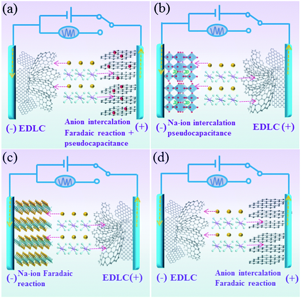 | ||
| Fig. 1 Schematic illustration of the working principles of (a) this Na-ion hybrid capacitor and (b–d) conventional Na-ion hybrid capacitors. Dotted lines in red and yellow mean the transfer of ions and electrons, respectively. | ||
The scanning electron microscopy (SEM) image of the used cathode (BG) shows the lateral feature of the material (Fig. S1, ESI†). The energy dispersive X-ray spectroscopy (EDX) mapping indicates the homogeneous distribution of carbon and boron atoms in the whole sample (Fig. S1c, ESI†). The nitrogen adsorption–desorption isotherm of the BG sample presents a BET specific surface area of 19.7 m2 g−1 (Fig. S1d, ESI†). The thickness of BG is in the range of 120 to 150 nm (Fig. S2, ESI†). The graphitic features of the BG are confirmed by the clear lattice fringes with a spacing of 0.34 nm in the HRTEM image (Fig. S3, ESI†). XPS analysis was performed to further confirm the presence of interstitial BG bonds in the graphite (Fig. S4, ESI†). The B1s peak is split into four peaks, suggesting that the boron atom exists in four different chemical environments (186.7 eV for B4C, 189 eV for B3C, 192 eV for BC2O and 193.8 eV for BCO2).24a,b The small amount of oxygen observed in the BG may be because of the doping synthesis in an open environment instead of in a glove box under inert atmosphere. In addition, the substituted boron concentration in the graphite sheets was determined to be about 0.75%. Fig. S5 (ESI†) presents the typical SEM image of the used anode (hollow carbon) with the spherical nanostructure and many cracking parts. The hollow carbon spheres with many cracking parts are chosen as the anode based on the consideration that the fascinating open structure with a large interior void space can serve as an ion reservoir, allowing electrolyte ions to rapidly form electrical-double-layer interfaces at both the inner and outer surfaces.24c More importantly, the hollow structures have good mechanical stability, which can efficiently enhance the tolerance to the structural variation during long-term cycling.24d
The charge storage kinetics of the cathode (BG) was analyzed using sweep-rate-dependent cyclic voltammetry (CV). The shape of the CV curve for the BG electrode is well preserved with increasing the sweep rate (Fig. S6, ESI†). In general, the current (i) fits a relationship with the sweep rate (v) according to the equation of i = avb, in which a and b are constants. The b value can be utilized to qualitatively analyze the degree of capacitive effect with a value of 0.5 indicating diffusion-controlled charge-storage and a value of 1 suggesting a capacitive (or pseudocapacitive) charge-storage mechanism.14,15 The value of b can be determined from the slope of log (i) versus log (v) (Fig. 2a and Fig. S7, ESI†). The b value calculated at the cathodic peak regimes was estimated to be 0.78. When the potentials were far away from the cathodic peak potential, the b values were more close to 1 (Fig. 2b). This suggests that the total charge storage in the BG electrode is a combination of a capacitance (or pseudocapacitance)-controlled process and a diffusion-controlled redox process. According to the power–law relationship, the ratio of capacitive (or pseudocapacitive) contribution can be quantified from another CV analysis by separating the current (i) into capacitive (k1v) effects (electrical-double-layer capacitance or redox pseudocapacitance) and diffusion-controlled behavior (k2v1/2) as follows: i = k1v + k2v1/2. Then, the k1 and k2 contents at various potentials can be determined by plotting i/v1/2versus v1/2.14,15,17Fig. 2c presents the result of this analysis for the BG electrode at 0.5 mV s−1 with a capacitive (or pseudocapacitive) contribution of 65%. Furthermore, when the sweep rate increases, the ratio of the capacitive (or pseudocapacitive) contribution gradually increases with a maximum contribution value of 92% at a sweep rate of 9 mV s−1 (Fig. 2d). Generally, there are two types of capacitive charge storage (the electrical-double-layer one and the pseudo-capacitive one). For the electrical-double-layer type electrode, it requires a high specific surface area (like activated carbon, over 2000 m2 g−1) since its specific capacitance is proportional to the specific surface area to a certain extent.1b As is well-known, graphite is never an electrical-double-layer type electrode because of its low specific surface area (<20 m2 g−1). Thus, the capacitive contribution in the BG electrode is basically from the pseudocapacitive reaction. DFT simulations indicate that the doped B (Fig. S8, ESI†) may act as a favourable anion (PF6−) binding site for a reversible and fast p-typed pseudocapacitive redox reaction (Fig. S9, ESI†). For the pure graphite electrode, the b value for the cathodic peaks is estimated to be 0.51 (Fig. S10, ESI†), which indicates that its kinetics should be accurately described as the diffusion-limited anion intercalation/deintercalation redox process with negligible pseudocapacitances.
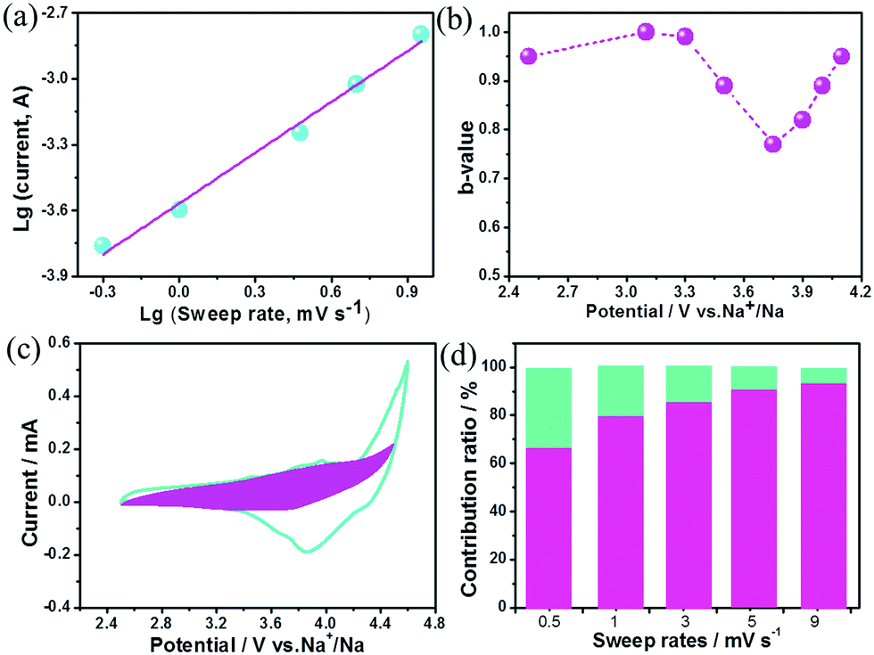 | ||
| Fig. 2 Kinetics analysis of the electrochemical behavior in the BG electrode. (a) The determination of the b-value at cathodic peak regimes. (b) The calculated b values at various potentials. (c) Separation of the pseudocapacitive and diffusion currents at a scan rate of 0.5 mV s−1. (d) Contribution ratios of capacitances from the surface-controlled pseudocapacitive reaction and diffusion-limited intercalation/deintercalation reaction at various sweep rates. | ||
From galvanostatic charge/discharge tests of the BG electrode in a half cell (Fig. S11a, ESI†), anion storage took place at the potential platform between 4 and 4.5 V (vs. Na+/Na), which was much higher than those of most intercalation metal oxide compounds for Na+ ion storage (2.5–4 V vs. Na+/Na).24c The BG electrode exhibited specific capacitances of 155, 142, 131, 115 and 96 F g−1 at current densities of 0.5, 1, 1.5, 2 and 3 A g−1, respectively (Fig. S11b, ESI†). The HC electrode was tested in the potential range of 0.5 and 2.5 V vs. Na+/Na (Fig. S12, ESI†) in a half cell. The linear charge/discharge profile of the HC electrode indicates a close-to-ideal EDLC contribution, which is consistent with the CV curve with a rectangular shape (Fig. S13, ESI†). The HC electrode shows a specific capacitance of 221 F g−1 at a small current density of 0.5 A g−1, which slightly decreases to 170 F g−1 at a large current density of 3 A g−1 (Fig. S12b, ESI†). Based on the above electrochemical performances in half cells, the calculated mass ratios between BG and HC were in the range of 1![[thin space (1/6-em)]](https://www.rsc.org/images/entities/char_2009.gif) :0.57 to 1:0.69 at various current densities. Then Na-ion hybrid capacitors were fabricated with BG as the cathode and HC as the anode. The slopes of the galvanostatic charge/discharge curves are not strictly linear especially at small current densities (Fig. 3a) due to the co-existence of EDLC-type (anode) and pseudocapacitive (cathode) charge storage features in the fabricated Na-ion hybrid capacitors. Moreover, it is capable of fast charging/discharge within one minute at 2.75 A g−1. The specific capacitances are 49, 46 and 42 F g−1 based on the total mass of the cathode and anode at current densities of 0.25, 0.5 and 0.75 A g g−1, respectively. Even when the current density increases to 2.75 A g−1, the specific capacitance still remains 23 F g−1 (Fig. 3b). As discussed in Fig. 2, the contributions of charge storage in the B–G cathode were composed of both surface-controlled pseudocapacitance and diffusion-controlled intercalation/deintercalation redox reactions. The capacitance decreases when the current density increases to 2.75 A g−1, which may result from the diffusion-controlled anion reaction with slow kinetics in the cathodes. When the current densities gradually increase, the simultaneously increasing polarization of the anion intercalation/deintercalation redox reaction leads to the decrease of the specific capacitance. In contrast, for the Na-ion hybrid capacitor based on un-doped graphite sheets as the cathode (with diffusion-controlled kinetics) and hollow carbon as the anode (with EDL typed surface-controlled kinetics), its specific capacitance decreases more rapidly (Fig. S14, ESI†), which further demonstrates the importance of enhancing the pseudocapacitive contribution in the cathode for anion storage.
:0.57 to 1:0.69 at various current densities. Then Na-ion hybrid capacitors were fabricated with BG as the cathode and HC as the anode. The slopes of the galvanostatic charge/discharge curves are not strictly linear especially at small current densities (Fig. 3a) due to the co-existence of EDLC-type (anode) and pseudocapacitive (cathode) charge storage features in the fabricated Na-ion hybrid capacitors. Moreover, it is capable of fast charging/discharge within one minute at 2.75 A g−1. The specific capacitances are 49, 46 and 42 F g−1 based on the total mass of the cathode and anode at current densities of 0.25, 0.5 and 0.75 A g g−1, respectively. Even when the current density increases to 2.75 A g−1, the specific capacitance still remains 23 F g−1 (Fig. 3b). As discussed in Fig. 2, the contributions of charge storage in the B–G cathode were composed of both surface-controlled pseudocapacitance and diffusion-controlled intercalation/deintercalation redox reactions. The capacitance decreases when the current density increases to 2.75 A g−1, which may result from the diffusion-controlled anion reaction with slow kinetics in the cathodes. When the current densities gradually increase, the simultaneously increasing polarization of the anion intercalation/deintercalation redox reaction leads to the decrease of the specific capacitance. In contrast, for the Na-ion hybrid capacitor based on un-doped graphite sheets as the cathode (with diffusion-controlled kinetics) and hollow carbon as the anode (with EDL typed surface-controlled kinetics), its specific capacitance decreases more rapidly (Fig. S14, ESI†), which further demonstrates the importance of enhancing the pseudocapacitive contribution in the cathode for anion storage.
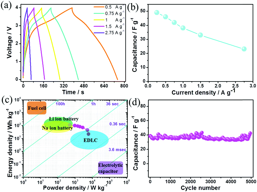 | ||
| Fig. 3 Electrochemical performance of the fabricated Na-ion hybrid capacitor. (a) Galvanostatic charge/discharge curves and (b) specific capacitances at various current densities. (c) Ragone plot and the comparison with other electrochemical energy storage and conversion devices. (d) The cycle behavior at 1 A g−1. | ||
In addition, the Na-ion hybrid capacitor with BG as the cathode exhibits a maximum energy density of 108 W h kg−1 at a power density of 495 W kg−1, which is comparable to some Li-ion hybrid capacitors4,20b,21c and most Na-ion hybrid capacitors (Fig. S15, ESI†).11–13,20–22 An impressive power density of 6100 W kg−1 is delivered at an energy density of 20 W h kg−1 (Fig. 3c). After 5000 cycles, 97% of the initial capacitance is retained (Fig. 3d), indicating the excellent cycling stability. The initial discharge/charge times of the BG electrode are 316/206 seconds at 0.25 A g−1 (Fig. S16, ESI†), resulting in an irreversible capacitance loss of 15% due to the formation of the solid–electrolyte-interface (SEI) film on the negative electrode.24e It should be noted that there is a slight decay of the specific capacitance over the initial 100 cycles (Fig. 3d), which may result from the passivation of the anode towards the electrolyte with the formation of the SEI film. Actually, for the HC electrode, the irreversible CV curve for the first cycle at a potential of ∼0.7 V vs. Na+/Na (Fig. S17a, ESI†) is mainly associated with the formation of the SEI film on its surface, which is mainly composed of some inorganic Na salts (such as NaF) according to the elemental mapping distribution of the electrode (Fig. S17b, ESI†). On the one hand, the irreversible reactions of the electrolyte decomposition in the initial cycles cannot be totally prevented. The initial SEI film would lead to a relatively larger charge transfer resistance (Fig. S17c, ESI†) and the degradation of conductivity in the anode, which could potentially be the origin of the observed continuous loss of capacitance in the initial 100 cycles. On the other hand, the formation of a SEI film on the anode surface is necessary for maintaining its stability.24a,e The stable SEI formed after a few dozen cycles could suppress the further decomposition of the NaPF6 based electrolyte while enabling the transportation of Na+ ions, thus allowing stable cycling of the fabricated Na-ion hybrid capacitor.24e After the initial 100 cycles, the hybrid device displayed high coulombic efficiencies above 99.5% (Fig. S18, ESI†). Table S1 (ESI†) summarizes the comparison of this Na-ion capacitor with other advanced metal-ion hybrid capacitors, revealing that our fabricated hybrid device reaches the state-of-the-art performance.
The superior electrochemical performances of this Na-ion capacitor were attributed to the following aspects. First, a wide operating voltage (0–4 V) was achieved through coupling the high-potential BG electrode with the low-potential HC electrode. Since the energy stored in the electrochemical capacitor is proportional to its capacitance and the square of its operating voltage, the wide operating voltage (up to 4 V) of the fabricated hybrid device could remarkably improve the energy density due to its quadruple increase. Second, the sluggish kinetics of the negative electrode with the Na-ion redox reaction in conventional Na-ion hybrid capacitors was successfully overcome by replacing an EDLC-type electrode with fast kinetics in this reported Na-ion capacitor. Third, the high pseudocapacitance contribution in the cathode for anion storage can further promote the fast kinetics of this hybrid device. To prove the charge-storage mechanism in the cathode, the BG electrode after being charged to 4 V was characterized using SEM elemental mapping (Fig. S19, ESI†). The P elements distributed uniformly within the electrode should arise from the electrolyte (PF6−). To determine whether intercalation/deintercalation or adsorption/desorption of the PF6− ions occurred onto/from the BG electrode, in situ electrochemical-Raman spectroscopy was performed on the positive electrode in the hybrid devices during the charge/discharge process. The pristine BG electrode shows an intense sharp peak at ∼1580 cm−1 (G band) corresponding to the sp2-hybridized carbon atoms in the hexagonal framework. Upon charging, the G band gradually becomes a broad shoulder, and then splits into a doublet (Fig. 4a). Meanwhile, the intensity of the D band at ∼1340 cm−1 becomes slightly weak during charging. These signal changes of the G and D bands in Raman spectroscopy indicate the presence of the anion intercalated graphite compound upon charging. This observation is similar to the AlCl4− ion intercalation/de-intercalation into/from graphite.25 The Raman spectral changes are then reversed during the discharge process. To gain further insight into the anion storage, the diffusion barriers of PF6− ion trajectories in the graphite layers and B-doped graphite layers were then investigated by DFT calculation. Two possible anion diffusion paths on the unit cell of C64 and C63B, respectively, were considered (Fig. S20, ESI†). The optimized energy barrier for PF6 diffusion in the graphite layers is 0.25 eV. However, the energy barrier in the B-doped graphite along the same direction gives rise to a much lower activation energy barrier of 0.16 eV (Fig. 4b). As is well-known, the ion diffusion constant can be evaluated by the following equation: D ∼ exp(−Ea/kBT), where T is the temperature (300 K at room temperature), kB is Boltzmann's constant (8.617 × 10⁻⁵ eV K−1), and Ea is the diffusion barrier obtained by DFT calculation.26 According to this equation, the PF6− ion diffusion mobility in the B-doped graphite is much faster than that in the un-doped one. Specifically, at room temperature the PF6− ion diffusion mobility on the B-doped graphite layers is estimated to be 32 times faster than that on the undoped graphite layers. This fast anion diffusion is another reason for the high power density of the Na ion hybrid capacitor based on the BG cathode.
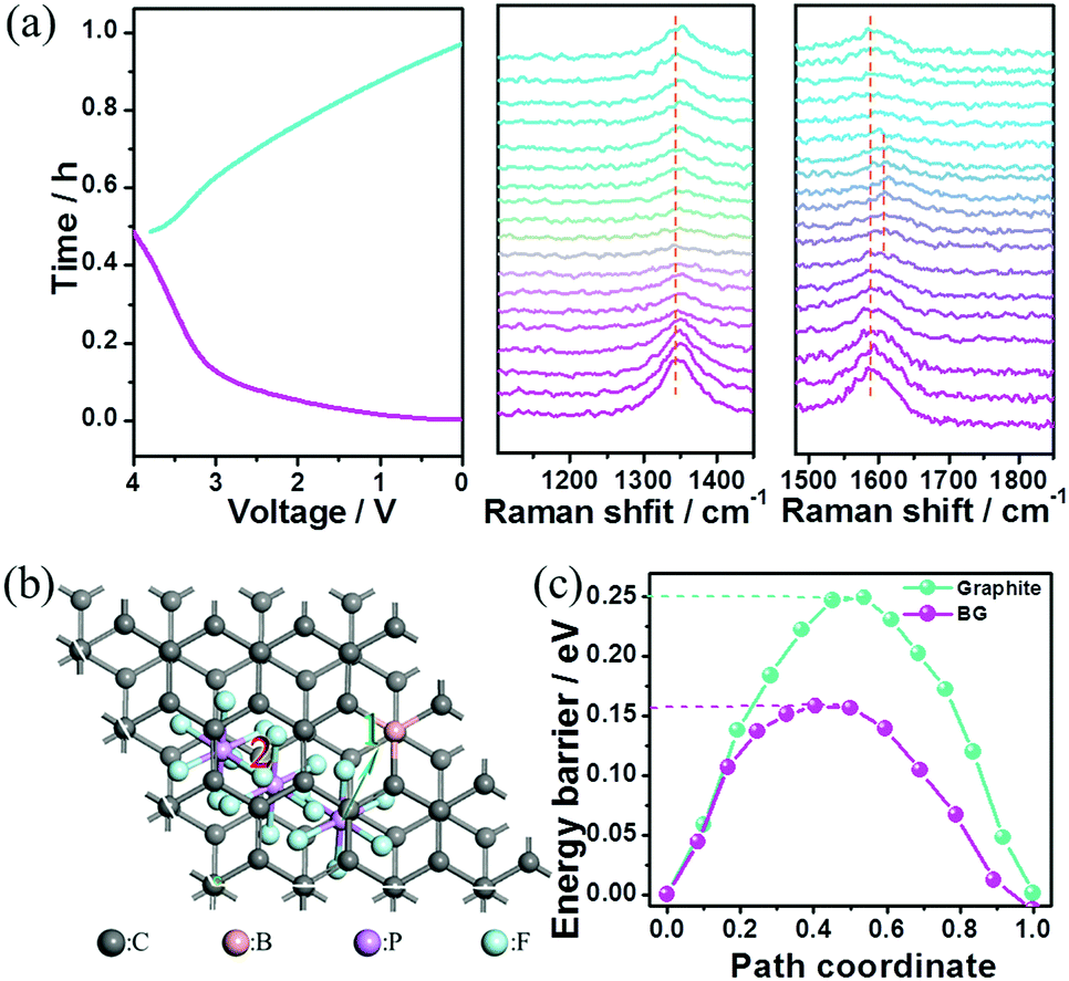 | ||
| Fig. 4 (a) The in situ electrochemical-Raman spectroscopy test of the BG electrode in the Na-ion hybrid capacitor. (b) and (c) The optimized PF6 diffusion in the B-doped graphite layers and the corresponding energy barriers by DFT calculation. | ||
Currently, several kinds of electrochemical energy storage devices based on the intercalation of anions into carbonaceous cathodes have been reported including Al-ion batteries,25,28 dual-graphite batteries,27a–c dual-ion batteries27d–g,28a and symmetric and hybrid supercapacitors.23,29 In terms of the charge storage mechanism, it should be noted that there are two differences between this hybrid device and previously reported devices. First, in the case of the cathode for anion storage, both the surface-controlled pseudocapacitive redox reaction and diffusion-controlled intercalation/deintercalation redox reaction exist in our Na-ion hybrid capacitor. Nevertheless, only the diffusion-controlled intercalation/deintercalation redox reaction for anion storage was demonstrated in previously reported electrochemical energy storage devices (such as Al-ion batteries,25,28 dual-graphite batteries,27a–c dual-ion batteries27d–g,28a and symmetric and hybrid supercapacitors23,29). The high contribution ratio of the surface-controlled pseudocapacitive reaction for anion storage in the BG electrode plays an extremely crucial role in the high-rate capability of this Na-ion hybrid capacitor. Secondly, as for the anode, our hybrid device is coupled with an EDL-type hollow carbon electrode, whose kinetics are totally distinct from those of anodes based on Al3+ stripping/plating for Al-ion batteries25,28 and metal ion intercalation (or conversion or alloying) reactions for dual-graphite batteries and dual-ion batteries.27,28a
Conclusions
In summary, we presented a novel Na-ion hybrid capacitor with anion storage in the cathode from both a surface-controlled pseudocapacitive reaction and a diffusion-limited intercalation/deintercalation reaction. This hybrid device exhibited superior electrochemical properties in terms of a high operating voltage of 4 V, a maximum energy density of 108 W h kg−1, and prolonged cycling stability over 5000 cycles with 97% capacitance retention, which were notable results compared with conventional metal-ion hybrid capacitors. This work will benefit the development of pseudocapacitive electrode materials for anion storage towards the applications of high-rate electrochemical energy storage devices.Conflicts of interest
The authors declare no competing financial interest.Acknowledgements
This work was financially supported by the Postgraduate Research Award of Queensland University of Technology (QUTPRA). The computational resources generously provided by the High Performance Computing Center of Nanjing Tech University are greatly appreciated.Notes and references
- (a) F. Wang, X. Wu, X. Yuan, Z. Liu, Y. Zhang, L. Fu, Y. Zhu, Q. Zhou, Y. Wu and W. Huang, Chem. Soc. Rev., 2017, 46, 6816 RSC; (b) S. Tabata, Y. Isshiki and M. Watanabe, J. Electrochem. Soc., 2008, 155, K42 CrossRef CAS.
- G. G. Amatucci, F. Badway, A. D. Pasquier and T. Zheng, J. Electrochem. Soc., 2001, 148, A930 CrossRef CAS.
- (a) H. Wang, C. Zhu, D. Chao, Q. Yan and H. J. Fan, Adv. Mater., 2017, 29, 1702093 CrossRef PubMed; (b) V. Aravindan, J. Gnanaraj, Y. S. Lee and S. Madhavi, Chem. Rev., 2014, 114, 11619 CrossRef CAS PubMed; (c) Y. Ma, H. Chang, M. Zhang and Y. Chen, Adv. Mater., 2015, 27, 5296 CrossRef CAS PubMed; (d) K. Naoi, W. Naoi, S. Aoyagi, J. I. Miyamoto and T. Kamino, Acc. Chem. Res., 2013, 46, 1075 CrossRef CAS PubMed.
- (a) E. Lim, H. Kim, C. Jo, J. Chun, K. Ku, S. Kim, H. I. Lee, I. S. Nam, S. Yoon, K. Kang and J. Lee, ACS Nano, 2014, 8, 8968 CrossRef CAS PubMed; (b) Z. Chen, Y. Yuan, H. Zhou, X. Wang, Z. Gan, F. Wang and Y. Lu, Adv. Mater., 2014, 26, 339 CrossRef CAS PubMed; (c) X. Yu, C. Zhan, R. Lv, Y. Bai, Y. Lin, Z. H. Huang, W. Shen, X. Qiu and F. Kang, Nano Energy, 2015, 15, 43 CrossRef CAS.
- (a) F. Zhang, T. Zhang, X. Yang, L. Zhang, K. Leng, Y. Huang and Y. Chen, Energy Environ. Sci., 2013, 6, 1623 RSC; (b) N. Aruna, A. Jain, V. Aravindand, S. Jayaraman, W. C. Ling, M. P. Srinivasan and S. Madhavi, Nano Energy, 2015, 12, 69 CrossRef.
- (a) J. H. Won, H. M. Jeong and J. K. Kang, Adv. Energy Mater., 2016, 7, 1601355 CrossRef; (b) W. S. V. Lee, E. Peng, M. Li, X. Huang and J. M. Xue, Nano Energy, 2016, 27, 202 CrossRef CAS.
- (a) E. Iwama, N. Kawabata, N. Nishio, K. Kisu, J. Miyamoto, W. Naoi, P. Rozier, P. Simon and K. Naoi, ACS Nano, 2016, 10, 5398 CrossRef CAS PubMed; (b) C. Liu, C. Zhang, H. Song, C. Zhang, Y. Liu, X. Nan and G. Cao, Nano Energy, 2016, 22, 290 CrossRef CAS.
- C. Liu, C. Zhang, H. Fu, X. Nan and G. Cao, Adv. Energy Mater., 2017, 7, 1601127 CrossRef.
- Z. Chen, V. Augustyn, X. Jia, Q. Xiao, B. Dunn and Y. Lu, ACS Nano, 2012, 6, 4319 CrossRef CAS PubMed.
- (a) F. Wang, X. Wang, Z. Chang, X. Wu, X. Liu, L. Fu, Y. Zhu, Y. Wu and W. Huang, Adv. Mater., 2015, 27, 6962 CrossRef CAS PubMed; (b) J. Ding, H. Wang, Z. Li, K. Cui, D. Karpuzov, X. Tan, A. Kohandehghan and D. Mitlin, Energy Environ. Sci., 2015, 8, 941 RSC.
- (a) J. Ding, Z. Li, K. Cui, S. Boyer, D. Karpuzov and D. Mitlin, Nano Energy, 2016, 23, 129 CrossRef CAS; (b) R. Thangavel, K. Kaliyappan, K. Kang, X. Sun and Y. S. Lee, Adv. Energy Mater., 2016, 6, 1502199 CrossRef; (c) H. Li, Y. Zhu, S. Dong, L. Shen, Z. Chen, X. Zhang and G. Yu, Chem. Mater., 2016, 28, 5753 CrossRef CAS; (d) E. Lim, C. Jo, M. S. Kim, M. H. Kim, J. Chun, H. Kim, J. Park, K. C. Roh, K. Kang, S. Yoon and J. Lee, Adv. Funct. Mater., 2016, 26, 3711 CrossRef CAS.
- H. Li, L. Peng, Y. Zhu, X. Zhang and G. Yu, Nano Lett., 2016, 16, 5938 CrossRef CAS PubMed.
- C. Wang, F. Wang, Z. Liu, Y. Zhao, Y. Liu, Q. Yue, H. Zhu, Y. Deng, Y. Wu and D. Zhao, Nano Energy, 2017, 41, 674 CrossRef CAS.
- (a) T. Brezesinski, J. Wang, S. H. Tolbert and B. Dunn, Nat. Mater., 2010, 9, 146 CrossRef CAS PubMed; (b) M. Sathiya, A. S. Prakash, K. Ramesha, J. M. Tarascon and A. K. Shukla, J. Am. Chem. Soc., 2011, 133, 16291 CrossRef CAS PubMed; (c) V. Augustyn, P. Simon and B. Dunn, Energy Environ. Sci., 2014, 7, 1597 RSC.
- V. Augustyn, J. Come, M. A. Lowe, J. W. Kim, P. L. Taberna, S. H. Tolbert, H. D. Abruña, P. Simon and B. Dunn, Nat. Mater., 2013, 12, 518 CrossRef CAS PubMed.
- (a) C. Chen, Y. Wen, X. Hu, X. Ji, M. Yan, L. Mai, P. Hu, B. Shan and Y. Huang, Nat. Commun., 2015, 6, 6929 CrossRef CAS PubMed; (b) G. A. Muller, J. B. Cook, H. S. Kim, S. H. Tolbert and B. Dunn, Nano Lett., 2015, 15, 1911 CrossRef CAS PubMed.
- (a) D. Chao, C. Zhu, P. Yang, X. Xia, J. Liu, J. Wang, X. Fan, S. V. Savilov, J. Lin, H. J. Fan and Z. X. Shen, Nat. Commun., 2016, 7, 12122 CrossRef CAS PubMed; (b) D. Chao, P. Liang, Z. Chen, L. Bai, H. Shen, X. Liu, X. Xia, Y. Zhao, S. V. Savilov, J. Lin and Z. X. Shen, ACS Nano, 2016, 10, 10211 CrossRef CAS PubMed.
- (a) Y. Zhu, L. Peng, D. Chen and G. Yu, Nano Lett., 2016, 16, 742 CrossRef CAS PubMed; (b) Y. Dong, B. Wang, K. Zhao, Y. Yu, X. Wang, L. Mai and S. Jin, Nano Lett., 2017, 17, 5740 CrossRef CAS PubMed; (c) X. Xu, J. Liu, Z. Liu, J. Shen, R. Hu, J. Liu, L. Ouyang, L. Zhang and M. Zhu, ACS Nano, 2017, 11, 9033 CrossRef CAS PubMed.
- (a) H. S. Kim, J. B. Cook, H. Lin, J. S. Ko, S. H. Tolbert, V. Ozolins and B. Dunn, Nat. Mater., 2017, 16, 454 CrossRef CAS PubMed; (b) J. Zhang, C. Du, Z. Dai, W. Chen, Y. Zheng, B. Li, Y. Zong, X. Wang, J. Zhu and Q. Yan, ACS Nano, 2017, 11, 10599 CrossRef CAS PubMed; (c) Y. Jiang, Y. Li, P. Zhou, Z. Lan, Y. Lu, C. Wu and M. Yan, Adv. Mater., 2017, 29, 1606499 CrossRef PubMed.
- (a) Y. Dall’Agnese, P. L. Taberna, Y. Gogotsi and P. Simon, J. Phys. Chem. Lett., 2015, 6, 2305 CrossRef PubMed; (b) X. Wang and G. Shen, Nano Energy, 2015, 15, 104 CrossRef.
- (a) K. Naoi, T. Kurita, M. Abe, T. Furuhashi, Y. Abe, K. Okazaki, J. Miyamoto, E. Iwama, S. Aoyagi, W. Naoi and P. Simon, Adv. Mater., 2016, 28, 6751 CrossRef CAS PubMed; (b) T. Li, M. Beidaghi, X. Xiao, L. Huang, Z. Hu, W. Sun, X. Chen, Y. Gogotsi and J. Zhou, Nano Energy, 2016, 26, 100 CrossRef CAS; (c) H. Wang, Y. Zhang, H. Ang, Y. Zhang, H. T. Tan, Y. Zhang, Y. Guo, J. B. Franklin, X. L. Wu, M. Srinivasan, H. J. Fan and Q. Yan, Adv. Funct. Mater., 2016, 26, 3082 CrossRef CAS.
- (a) L. Shen, H. Lv, S. Chen, P. Kopold, P. A. van Aken, X. Wu, J. Maier and Y. Yu, Adv. Mater., 2017, 29, 1700142 CrossRef PubMed; (b) Y. E. Zhu, L. Yang, J. Sheng, Y. Chen, H. Gu, J. Wei and Z. Zhou, Adv. Energy Mater., 2017, 7, 1701222 CrossRef; (c) Z. Le, F. Liu, P. Nie, X. Li, X. Liu, Z. Bian, G. Chen, H. B. Wu and Y. Lu, ACS Nano, 2017, 11, 2952 CrossRef CAS PubMed.
- (a) H. Wang and M. Yoshio, J. Power Sources, 2008, 177, 681 CrossRef CAS; (b) H. Wang and M. Yoshio, Chem. Commun., 2010, 46, 1544 RSC; (c) G. Park, N. Gunawardhana, C. Lee, S. M. Lee, Y. S. Lee and M. Yoshio, J. Power Sources, 2013, 236, 145 CrossRef CAS; (d) G. Park, N. Gunawardhana, C. Lee, S. M. Lee, Y. S. Lee and M. Yoshio, J. Power Sources, 2013, 236, 145 CrossRef CAS; (e) J. Gao, S. Tian, L. Qi, M. Yoshio and H. Wang, J. Power Sources, 2015, 297, 121 CrossRef CAS.
- (a) Z. S. Wu, W. Ren, L. Xu, F. Li and H. M. Cheng, ACS Nano, 2011, 5, 5463 CrossRef CAS PubMed; (b) Z. S. Wu, A. Winter, L. Chen, Y. Sun, A. Turchanin, X. Feng and K. Müllen, Adv. Mater., 2012, 24, 5130 CrossRef CAS PubMed; (c) Z. Zhang, M. Qin, B. Jia, H. Zhang, H. Wu and X. Qu, Chem. Commun., 2017, 53, 2922 RSC; (d) L. Liu, S. D. Xu, Q. Yu, F. Y. Wang, H. L. Zhu, R. L. Zhang and X. Liu, Chem. Commun., 2016, 52, 11693 RSC; (e) J. Y. Hwang, S. T. Myung and Y. K. Sun, Chem. Soc. Rev., 2017, 46, 3529 RSC.
- M. C. Lin, M. Gong, B. Lu, Y. Wu, D. Y. Wang, M. Guan, M. Angell, C. Chen, J. Yang, B. J. Hwang and H. Dai, Nature, 2015, 520, 325 CrossRef PubMed.
- (a) M. Peng, B. Li, H. Yan, D. Zhang, X. Wang, D. Xia and G. Guo, Angew. Chem., Int. Ed., 2015, 54, 6452 CrossRef CAS PubMed; (b) X. Wang, R. Xiao, H. Li and L. Chen, Phys. Rev. Lett., 2017, 118, 195901 CrossRef PubMed.
- (a) J. A. Seela and J. R. Dahn, J. Electrochem. Soc., 2000, 147, 892 CrossRef; (b) J. A. Read, A. V. Cresce, M. H. Ervin and K. Xu, Energy Environ. Sci., 2014, 7, 617 RSC; (c) S. Rothermel, P. Meister, G. Schmuelling, O. Fromm, H. W. Meyer, S. Nowak, M. Winter and T. Placke, Energy Environ. Sci., 2014, 7, 3412 RSC; (d) X. Tong, F. Zhang, B. Ji, M. Sheng and Y. Tang, Adv. Mater., 2016, 28, 9979 CrossRef CAS PubMed; (e) K. Beltrop, S. Beuker, A. Heckmann, M. Winter and T. Placke, Energy Environ. Sci., 2017, 10, 2090 RSC; (f) B. Ji, F. Zhang, X. Song and Y. Tang, Adv. Mater., 2017, 29, 1700519 CrossRef PubMed; (g) F. Wang, Z. Liu, P. Zhang, H. Li, W. Sheng, T. Zhang, R. Jordan, Y. Wu, X. Zhuang and X. Feng, Small, 2017, 13, 1702449 CrossRef PubMed; (h) J. M. Huesker, M. Winter and T. Placke, ECS Trans., 2015, 69, 9 CrossRef CAS.
- (a) M. Angell, C. J. Pan, Y. Rong, C. Yuan, M. C. Lin, B. J. Hwang and H. Dai, Proc. Natl. Acad. Sci. U. S. A., 2017, 114, 834 CrossRef CAS PubMed; (b) D. Y. Wang, C. Y. Wei, M. C. Lin, C. J. Pan, H. L. Chou, H. A. Chen, M. Gong, Y. Wu, C. Yuan, M. Angell, Y. J. Hsieh, Y. H. Chen, C. Y. Wen, C. W. Chen, B. J. Hwang, C. C. Chen and H. Dai, Nat. Commun., 2017, 8, 14283 CrossRef CAS PubMed; (c) Y. Wu, M. Gong, M. C. Lin, C. Yuan, M. Angell, L. Huang, D. Y. Wang, X. Zhang, J. Yang, B. J. Hwang and H. Dai, Adv. Mater., 2016, 28, 9218 CrossRef CAS PubMed.
- A. Borenstein, R. Attias, O. Hanna, S. Luski, R. B. Kaner and D. Aurbach, ChemElectroChem, 2017, 4, 2660 CrossRef CAS.
Footnotes |
| † Electronic supplementary information (ESI) available. See DOI: 10.1039/c8mh00156a |
| ‡ These authors equally contributed to this work. |
| This journal is © The Royal Society of Chemistry 2018 |