Solar-driven photothermal nanostructured materials designs and prerequisites for evaporation and catalysis applications

Liangliang Zhu a, Minmin Gao a, Connor Kang Nuo Peh a and Ghim Wei Ho *abc
aDepartment of Electrical and Computer Engineering, National University of Singapore, 4 Engineering Drive 3, 117583, Singapore. E-mail: elehgw@nus.edu.sg
bEngineering Science Programme, National University of Singapore, 9 Engineering Drive 1, 117575, Singapore
cInstitute of Materials Research and Engineering, A*STAR (Agency for Science, Technology and Research), 3 Research Link, 117602, Singapore

Received 7th December 2017 , Accepted 30th January 2018

First published on 30th January 2018


Abstract

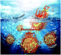
Solar energy is a major source of renewable energy with the potential to meet the energy demand and to support the sustainable development of the world. The efficient harvesting and conversion of solar energy is one of the key factors to maximize the utilization of solar energy. In general, solar energy can be harnessed and converted into various kinds of energy, including electricity, fuels and thermal energy, through photovoltaic, photochemical and photothermal processes, respectively. Among these technologies, photothermal conversion is a direct conversion process that has attained the highest achievable conversion efficiency. The photothermal effect has been used as a novel strategy to augment vaporization and catalysis performance. In this review, we look into the basis of the photothermal conversion process, the design of efficient photothermal conversion materials in terms of both light harvesting and thermal management, a fundamental understanding of various system schemes, and the recent progress in photothermal evaporation and catalysis applications. This review aims to afford researchers with a better understanding of the photothermal effect and provide a guide for the rational design and development of highly efficient photothermal materials in energy and environmental fields.


image file: c7mh01064h-p1.tif

Liangliang Zhu

Liangliang Zhu received his PhD degree in Material Chemical Engineering at Nanjing University of Technology, China, in 2013. He is now a research fellow at the Department of Electrical & Computer Engineering at National University of Singapore (NUS). His current research interest is the preparation of photothermal materials for water evaporation and energy generation.

image file: c7mh01064h-p2.tif

Minmin Gao

Minmin Gao received her BEng (Hons) degree in Electrical Engineering from National University of Singapore (NUS) in 2012, as well as her PhD in 2016 under the supervision of Associate Professor Dr Ghim Wei Ho. Her research interest currently focuses on TiO2-based core–shell nanostructures for catalytic applications.

image file: c7mh01064h-p3.tif

Connor Kang Nuo Peh

Connor Peh received his BEng (Hons) and PhD degrees from National University of Singapore in 2009 and 2016, respectively. He is currently a research fellow in NUS in A/Prof. Ho Ghim Wei's group. His current research interests primarily focus on clean energy generation, photocatalytic and photoelectrochemical water splitting and the development of materials to harness sunlight in various forms.

image file: c7mh01064h-p4.tif

Ghim Wei Ho

Ghim Wei Ho received her PhD for work in semiconductor nanostructures at the Nanoscience Centre, University of Cambridge in 2006. She is an associate professor at the Department of Electrical and Computer Engineering at the National University of Singapore (NUS). She is also one of the pioneer associates of the Engineering Science Programme (ESP) at NUS. Her research thrust is focused on the development of functional nanostructured materials for energy, environmental and healthcare applications.


1. Introduction

The global energy demand is ever-growing, driven by strong economic growth and an increasing pursuit of a high-quality of life.1,2 With rising concerns about the depletion of non-renewable resources alongside environmental issues, satisfying future energy needs in a sustainable way is a compelling need. Besides, the efficient utilization of renewable solar energy has attracted a lot of attention for decades as one of the most important strategies in green energy innovation. The critical challenge with this energy source is to enhance the utilization efficiency by extending the solar spectrum response from the UV to the visible, and even to the infrared (IR) region.3,4 Photothermal conversion is an important pathway to harvest solar energy and to enable its use in a broad range of applications, including environmental purification, water distillation/desalination and the catalytic production of fuels and chemicals.5–7 Solar water evaporation is highly promising for fresh water production for meeting remote areas/emergency needs, while photothermal catalysis provides an effective method to energetically drive solar fuels catalytic processes. However, the photothermal conversion efficiency is mainly limited by sunlight absorption and thermal management. Accordingly, rational material and system designs that favour efficient photon absorption and a reduction of superfluous heat losses are highly sought after.

Recent efforts in the development of solar absorber nanomaterials capable of broadband absorption, i.e. the visible to IR radiation, have become increasingly important from the viewpoint of energy conservation and sustainability for photothermal steam generation, water evaporation and catalysis.5,8 Herein, we review the recent progress in photothermal evaporation and catalysis applications together with the basis for photothermal conversion and the design of pertinent photothermal converting materials and system configurations for enhanced solar-driven vaporization and catalytic reactivity (Fig. 1). Various solar absorber materials, e.g. plasmonic metals,9–12 narrow bandgap semiconductors13–18 and carbon-based nanostructures,19–23 with efficient photothermal conversion capabilities will be discussed. Also, the diverse approaches that have been employed to enhance the light-to-heat conversion efficiency, such as tuning the structural composition, the hybridization of light absorber materials and the optimization of absorber/reactant configurations, will be covered. Finally, conclusions and the future perspectives for photothermal evaporation and catalysis will be presented. The goal of this review is to provide a background into photothermal conversion and to produce a guide that could shed some light on the key points to consider when designing solar absorber nanomaterials to aid the better future deployment of solar-driven evaporation and catalysis.


image file: c7mh01064h-f1.tif
Fig. 1 Schematic diagram of the scope of the present review.

2. Basis of photothermal conversion

It is essential that the optical and thermal properties of a material are considered to achieve an efficient photothermal conversion. The optical properties of materials, such as the absorption coefficient, the matching of a material's absorption spectrum to incident light and heat transfer and loss, play important roles in material selection and in optimization of the light-to-heat conversion (Fig. 2). In addition to the inherent properties of the utilized materials, other factors, such as the thermal stability, mechanical integrity and cost, should also be factored in for practical applications.
image file: c7mh01064h-f2.tif
Fig. 2 Schematic diagram of photothermal conversion.

2.1. Solar absorptance

Solar absorptance is a measure of the ability of a matter to absorb solar radiation, i.e. the ratio of the total absorbed solar radiation to the incident radiation. When a surface of a matter is subjected to electromagnetic radiation, a fraction of the photon energy can be transformed to other forms of energy, such as heat. The total solar absorptance for a given angle of incidence θ is obtained by weighting the spectral absorptance with the solar spectral irradiance distribution of a standard solar spectrum (AM 1.5) and integrating over the wavelengths in which the solar radiation reaches the solar absorber surface. Eqn (2.1) describes the total solar absorptance, α(θ), of a solar absorber for an incident angle of θ
 
image file: c7mh01064h-t1.tif(2.1)
where λmin and λmax are 0.3 μm and 2.5 μm, respectively, and θ is the angle of incidence of light measured from the surface normal of the absorber, A(λ) is the wavelength-dependent solar spectral irradiance and R(θ,λ) is the total reflectance at wavelength λ.24

As this review focuses mainly on utilization of the solar spectrum as the source of light (AM 1.5 reference spectrum), the material properties should be directed at achieving the maximum conversion from the sunlight that falls onto the Earth's surface. This means that the material should absorb as much of the electromagnetic radiation as possible from the wavelengths 300 nm to 2500 nm, with the visible range (400–700 nm) comprising ∼45% of the power, and the IR region (700–2500 nm) encompassing ∼52% of the power. The solar absorber material should be designed to have a high absorption in this region, with negligible reflectance in order to maximize the energy capture from the sun and to convert it to heat energy.

2.2. Heat transfer

In order to improve the efficiencies of solar heat absorbers, attention has to be placed on the heat transfer occurring in the system. Heat flows from one body to another in three main ways: conduction, convection and radiation; driven by thermal gradients between the bodies. Heat conduction occurs when heat flows from a higher temperature source to a lower temperature body by passing through a medium – passing on the energy by collisions between neighbouring particles.
 
image file: c7mh01064h-t2.tif(2.2)
where q is the heat transfer by conduction, k is the thermal conductivity of the material, A is the surface area of heat transfer, T1 and T2 are the temperatures of the two different bodies (assuming steady state temperatures) and L is the thickness of the medium.

Heat convection occurs by the motion of a mass of fluid carrying the energy away from the source of heat into a cooler part of the fluid. The convection heat transfer at a constant temperature in a fluid can be expressed as

 
q = [h with combining macron](TbodyTc)(2.3)
where q is the heat transfer by convection, [h with combining macron] is the average heat transfer coefficient, Tbody is the temperature of the body and Tc is the temperature of the surrounding fluid.

Lastly, heat radiation includes electromagnetic radiation from all objects. No medium of transfer is required and no mass is exchanged in this process. All objects constantly emit radiation based on their temperature and surface properties. Hotter objects usually emit much more radiation than cooler objects, in a relationship proportional to the fourth power of the absolute temperature. All objects therefore emit and absorb radiation at the same time, and the net effect is based on their temperature relative to their surroundings, and their emissivity. The Stefan–Boltzmann law can be re-expressed for a hot object in a cooler environment as

 
P = εσA(T4Tc4)(2.4)
where P is the thermal energy emitted per unit area, ε is the emittance of the object, A is the radiating area, T is the temperature of the radiator and Tc is the temperature of the cooler surroundings. Stefan's constant, σ, is taken as 5.6703 × 10⁸ W m−2 K−4.

As mentioned earlier, heat transfer occurs via three ways, and they all depend on a temperature gradient. Conduction is the most likely form of heat transfer for photothermal vaporization and catalysis applications, whereby a short transfer length associated with nanoscale dimensions and a high surface area coupled with an appropriate insulating material will certainly aid in efficient heat transfer. As long as the light irradiation continues, solar absorbers will always be in a higher thermal state than their surroundings. In order to improve the heating efficiencies, various measures can be taken to limit the heat loss. As a basic rule of thumb, a system will have to direct the produced heat to the target with minimal heat resistance, while minimizing the heat transfer to all other areas. Often systems designed for water evaporation and steam generation employ a wicking layer or channels to allow capillary action to draw water instantaneously to the target (surface of the solar absorber).19,21,24–31 Since most of these applications take place near room temperature, it would be prudent to design the system such that the solar absorber will transmit the heat immediately to its specific target, to optimally reduce its operating temperature to directly enhance the photothermal conversion efficiency.

3. Rational material design for enhanced photothermal conversion

Intensive efforts have been devoted to develop high-performance light-to-heat converting materials through a delicate tuning of the composition of solar absorbing materials, design of a multilayer coating and engineering the surface structure in such a way to achieve high solar absorptance with low thermal emittance and optical reflectance.10,32,33 Essentially, the key specification that determine the light-to-heat conversion efficiency is the light harvesting ability of the material. Unlike photothermal therapy, which requires a high single wavelength absorption in the near infrared (NIR) range, non-biomedical photothermal solar conversion requires the absorber materials to exhibit highly efficient and broadband optical absorption across the full solar spectrum range (from 250 to 2500 nm) with minimal transmittance and reflectance. Therefore, an overall high solar absorptance of a material is essential to achieve a high solar-to-thermal conversion. In this section, we discuss different strategies to enhance the solar absorption for efficient photothermal conversion using various solar absorber materials, i.e. metals, semiconductors and hybrid combinations of organic–inorganic and metallic semiconductors.

3.1. Plasmonic metals

The localized surface plasmon resonance (LSPR) effect of a metallic nanostructure is strongly correlated to the shape, size, dielectric coatings or medium around a particle and the assembly state34,35 (Fig. 3). Due to the nature of LSPR, metal-based plasmonic nanoparticles normally absorb at one or a few particular wavelengths, thus limiting their efficiency for solar–thermal conversion.36 To date, gold and silver are the most common materials adopted for photothermal applications. Silver is known for its high plasmonic resonance response and low plasmonic losses in the optical frequency regime, while gold is known for its visible-NIR plasmonic resonances and chemical stability.36,37 Recently, other metals have been developed for a wide range of plasmonic applications, such as aluminium, copper, molybdenum, cobalt, nickel and platinum.8,36,38,39 In general, reducing the shape symmetry or creating hollow structures could broaden the spectral LSPR band, while changing the size of the particles or the surrounding dielectric will cause mainly a shift in the LSPR band and auxiliary broadening of the absorption to a certain extent.9,40
image file: c7mh01064h-f3.tif
Fig. 3 Various strategies to enhance the optical absorption of plasmonic metals.
3.1.1. Influence of the geometry. A pronounced increase in the photothermal heating efficiency due to geometry modifications, such as designing asymmetric structures and elongated, sharp and tapered structures, has not only been predicted by numerical simulations,41–44 but also experimentally demonstrated by many research groups.20,44 Baffou et al. used Green's dyadic function to numerically investigate the mechanisms of the heating effects and efficiencies of homogeneous gold spherical nanoparticles and elongated nanorods colloidal with a constant metal volume in water. This method quantifies the heat generation in gold nanostructures and provides their internal distribution of the heating power density. It was observed that a red-shift occurs when the shape changes from spherical particles to nanorods, together with a substantial increase (∼60%) in heating efficiency.45 Moreover, plasmonic localized heat generation is often concentrated at sharp tips, corners and edge geometries, where the electromagnetic fields are significantly enhanced.9,20 This geometry effect has been validated by many researchers through simulations in assorted sharp geometry structures, including concave structures,46,47 nanocubes,47–49 octahedrons,50 nanoflowers/nanostars,32,51,52 nanocages,53 nanoprisms/nanoplates54,55 and octopods.56 Typically, thin and sharp structures facilitate the incoming electric field to intensely penetrate the constricted geometry, enabling the whole plasmonic matter to be actively involved in heating, while non-symmetrical and hollow structures contribute to broadband absorption. All these geometrical structure factors have explicitly been shown to enhance the overall solar-to-thermal conversion efficiency.
3.1.2. Influence of the dielectric environment. Other than the geometry aspect of the plasmonic material, the optical properties of the plasmonic materials in regard to the absorption resonance wavelength, intensity and range are also sensitive to the surrounding medium. Changing the dielectric environment around the plasmonic particles will result in a shift in the plasmon resonance wavelength.57 The surrounding dielectric layer can be made of semiconductors with appropriate bandgaps to enhance the overall light absorption. Chen et al. examined the photothermal conversion efficiency of Au nanoparticles with two different coatings, namely Au@ZnS and Au@Ag2S core–shell structures.10 Due to the change in the dielectric constant around the Au nanoparticles, a red-shift in absorption was observed for both the core–shell structures. Even though the absorption intensities of both core–shell structures were the same, the conversion efficiencies of Au@Ag2S was 1.4 times higher than that of Au@ZnS. This was attributed to the contrasting bandgaps of the Ag2S (0.9–1.1 eV) and ZnS (3.4–3.8 eV) shells, which resulted in a higher light absorption for Ag2S at the tested irradiation wavelength (809 nm), while ZnS was transparent to the specific light source. Moreover, it was shown that modification of the dielectric with increasing shell thickness resulted in a large red-shift and a significant enhancement in the plasmon resonance with the Au@Cu2O core–shell structure.58 Furthermore, they also found that the overall extinction spectral was not only determined by the effective shell thickness but also by the porosity of the shell. The increase in shell porosity led to a decrease in the permittivity of the shell, and as such, the less densely packed shell exhibited a narrower absorption spectral range. Hence, it was shown that it was possible to tune the absorption range, intensity and resonance wavelength via a dielectric coating of plasmonic materials. Nonetheless, the plasmonic properties may also be adversely attenuated by an inappropriate dielectric coating; hence the constituent, thickness and porosity of the dielectric medium have to be well-controlled for obtaining the desired photothermal effect.
3.1.3. Influence of the intra/interparticle coupling effect. Plasmonic optical coupling can effectively occur either on an isolated plasmonic nanoparticle (intraparticle) or between two separate neighbouring nanoparticles (interparticle). In order to modify the plasmonic characteristics of an isolated standalone nanostructure, the intraparticle plasmonic coupling scheme is often adopted. Generally, multiple plasmon resonance modes can be accomplished within an isolated nanoparticle, and a new plasmon mode can also be realized. The nanostructure can be configured to host multiple, localized surface plasmon-polariton resonances (SPPR) modes within a compatible interaction range, as such a coupling of individual components of the nanostructure make up the overall optical response. For instance, nanoflowers or nanostars with numerous tips can trigger intraparticle optical coupling between the tip modes and the core modes, which results in a red-shift and augmented dipole moment of the tip plasmons.51 Moreover, it has been reported that the coupling within the plasmon modes of the closely assembled tips engenders a strong intertip local field enhancement.59

It was also demonstrated that the plasmonic coupling effect is significant between adjacent interparticles.51 When two nanoparticles (i.e. a dimer) are placed close to each other, the electric field is concentrated in their gap due to plasmonic coupling. This highly localized field enhancement results in pronounced photothermal effects in the dimer gap. Notably, the overall photothermal performance establishes on both a collective heating ability and a coupling effect between the particles (Fig. 4a). Furthermore, the plasmonic coupling effect often brings about a change in optical absorption, which is highly dependent on the gap distance, the direction of the incident light and the number of particles involved.51,60–62 Hentschel et al. fabricated electron-beam patterned planar plasmonic gold hexamers and heptamers to theoretically and experimentally demonstrate that the interparticle gap and the arrangement of the particles play important roles in the plasmonic heating effect (Fig. 4b).63 The total heat generated by two interacting nanoparticles was numerically calculated to be dependent on the polarization of light. When the electric field of incident light is along the axis of the dimer, the total heat generated increases, while when it is in the perpendicular direction of the dimer, the heat generated is diminished.61 A similar conclusion was drawn by Abajo's group through studying the temperature distribution of dimer particles (Fig. 4c).60 The near-field and the temperature distribution corresponding to the dimer configuration are shown in Fig. 4d. It can be observed that the field intensity of the two particles can be tuned by the direction and the wavelength of the incident light, thus they feature different temperature profiles. In addition, the temperature of each sphere as a function of wavelength could be tuned by the gap distance between the dimers (Fig. 4e). Apart from planar interparticle coupling, collective interparticle coupling effect has experimentally been shown to enhance photothermal conversion. For instance, Huang et al. synthesized gold nanovesicles consisting of densely packed gold nanoparticles with a specific interparticle orientation. Such interparticle assembling induced an ultrastrong plasmonic coupling effect between the adjacent gold nanoparticles, whereupon the LSPR peak and absorption range were demonstrated to be tuneable by the number of inter-nanoparticle junctions (Fig. 4f).64


image file: c7mh01064h-f4.tif
Fig. 4 (a) Numerical simulations of the temperature increase within an N × N array of gold plasmonic nanoparticles, 40 nm in diameter, p = 300 nm in pitch, illuminated from the bottom (λ = 520 nm, P = 1 mW μm−2) showing a 3D model with N = 5 (i), the temperature in the centre of the array increases as a function of the size of the array (ii), temperature maps over an array of N2 = 4 × 4 cells (iii) and N2 = 10 × 10 cells (iv). Reprinted with permission from ref. 62. (b) Extinction spectra showing the effects of the plasmonic coupling of gold nanodisks with different interparticle gap separations. Reprinted with permission from ref. 63. (c) Sketch of a water-immersed gold dimer with two 100 nm spheres, illuminated by a 1 mW μm−2 p-polarized light plane-wave under an angle of incidence θ = 45° with respect to the axis or rotational symmetry. (d) Distribution of the electric near field (left) and temperature increase (right) under the illumination conditions of θ = 0 and λ = 500 nm (top) and θ = 45° and λ = 650 nm (bottom). (e) Temperature increase in the upper and lower spheres with different gap distances and wavelengths of the incident light. Reprinted with permission from ref. 60. (f) UV/Vis/NIR spectra and scanning electron microscopy (SEM) images (insets) of gold nanovesicles with a controllable interparticle distance with various concentrations in tetrahydrofuran. Reprinted with permission from ref. 64.

In general, plasmon-enhanced electric fields are highly sensitive to the arrangement of the particles and the incident light polarization. However, it is difficult to predict the effect of the photothermal heat generation, especially when the nanoparticles are randomly dispersed in solution. Therefore, in order to take advantage of the coupling effect through the assembly state of the nanoparticles, the arrangement and the design of the particles need to be carefully devised. The possible assembled configurations include highly organized particles on substrates, a hierarchical assembly of nanoparticles, and well encapsulated nanoparticles within a matrix.

3.2. Semiconducting materials

Bandgap engineering governs the light absorption, which in turn controls the photothermal conversion ability of semiconductor materials. Semiconducting materials are generally opaque in the visible and translucent in the IR. Their absorption in the visible spectral region is based on free carrier generation, which depends on the bandgap of the semiconductor, while some transition metal semiconductors have absorption in the NIR region, which has been attributed to either indirect interband transitions or the LSPR effect.65,66 The free carrier concentration in semiconductor material is much lower than in metals; however, it can be significantly increased via doping or by introducing vacancies, which result in either a shift of the band energy and/or the creation of energy states within the bandgap. The increased in free carrier concentration not only enhances the absorption of the semiconductor, but also improves the light-to-heat conversion efficiency due to a high probability of nonradiative recombination.
3.2.1. Bandgap engineering. It has been demonstrated that the optical absorption of a semiconductor can be modified as a result of bandgap engineering through adding impurities, self-doping, or introducing disorder to the surface layers to generate donor or acceptor states in the bandgap and/or reduce the bandgap. The smaller bandgap and/or mid-gap energy states are the dominant centres for optical excitation and relaxation, leading to a broadening of the light absorption range of the semiconductor materials.67 Ye et al. observed a broad absorption in magnesium-reduced TiO2 nanoparticles populated with oxygen vacancies.68 The resulting dark coloured TiOx exhibited an extended photoresponse from the UV to the NIR spectral regions. Moreover, it was also found that the optical absorption increased with the magnesium concentration, which brought about a decrease in the oxygen content in TiOx. Wang et al. presented Ti2O3 nanoparticles with excellent absorption capability across the whole solar spectrum, showing an average reflectance of less than 10%, lower than that of graphite (20%).69 Both the ultrasmall bandgap and nano-sized features of the Ti2O3 nanoparticles contributed to the high solar-to-thermal conversion efficiency of ∼92%. Ti2O3, with a stoichiometric phase of the lower oxidation state Ti3p, can be viewed as an extreme form of oxygen-deficient TiO2. When the concentration of oxygen vacancies reaches saturation beyond which the TiO2 structure is no longer sustainable, the stoichiometric Ti3p phase is then formed. Consequently, oxygen vacancies become the primary defects present in the partially oxidized TiO2.70 Unlike TiO2, which only absorbs in the UV region due to its large bandgap, the bandgap of the Ti2O3 semiconductor has been engineered to be much narrower, to absorb the full solar spectrum (Fig. 5a).69
image file: c7mh01064h-f5.tif
Fig. 5 (a) Illustration of electron–hole generation and relaxation in a typical semiconductor (left) and in narrow bandgap Ti2O3 (right). Reprinted with permission from ref. 69. (b) The absorption spectra with increasing Cu vacancy in Cu2S. (c) LSPR frequency dependence on the free carrier density and doping constraints. Reprinted with permission from ref. 71. (d) The presence of oxidants (iodine) causes the formation of copper vacancies, resulting in holes in the valence band of Cu2S and an enhanced LSPR. (e) The presence of electron donors (sodium biphenyl) causes the filling of the copper vacancies in Cu2S, resulting in quenching of the LSPR. Reprinted with permission from ref. 73.
3.2.2. Free-carrier-induced LSPR. Moreover, creating intrinsic defects or introducing extrinsic impurities in transition metal semiconductors has been reported to generate a strong LSPR in the valence band mainly at the NIR region. The absorption characteristics of the semiconductor are similar to those of metals.13,66 Hessel et al. prepared a Cu2−xSe semiconductor (bandgap 2.1 to 2.3 eV) with a relatively high hole-carrier concentration, which exhibited strong free carrier absorption (540 to 590 nm) due to direct interband transitions. Furthermore, the Cu deficiencies in the nonstoichiometric Cu2−xSe led to a high densities of holes and exhibited an NIR absorbance peak due to surface plasmon resonance.66 Similar phenomena have been observed in other semiconductors, such as Cu2−xS nanocrystals,18 Cu2−xS quantum dots,71 W18O49 nanowires17 and WO3−x nanocrystals.72

Unlike the LSPR of metal, which cannot be dynamically controlled once the nanostructure parameters (size, shape or material) are fixed, the LSPR response of semiconductors can be tuned by the free carrier concentration without modifying the structure. Luther et al. demonstrated tunability in the optical properties; as such, NIR absorbance was absent when the copper vacancies in Cu2S were minimal and conversely, the intensity and blue-shifts in the LSPR band progressively increased with the vacancies (Fig. 5b).71 Moreover, they showed that the LSPR frequency of the semiconductor nanocrystal could be modulated by the free carrier density and doping constraints (Fig. 5c). By tuning both the size and the doping concentration of semiconductor nanocrystals, the LSPRs could be tuned from the terahertz to NIR frequencies. In order for the LSPR response of a semiconductor to fall in the range of the solar spectra, the required doping concentration must be at least ∼1021 cm−3. Alivisatos's group verified this effect through exposing Cu2S nanorods to both oxidants (iodine) and reducing agents (sodium biphenyl) to facilitate the formation and filling of Cu vacancies, respectively.73 They found that as the amount of oxidant increased, more vacancies were created, which resulted in a gradual blue-shift and an increase in intensity of the LSPR band (Fig. 5d), while as the reducing agent was added, the progressive filling of vacancies resulted in the opposite effect, with a red-shift and reduction in intensity of the LSPR band (Fig. 5e).

3.2.3. Structural design. The other approach to improve the photothermal properties of semiconductor materials is through constructing a hierarchical/superstructure that favours light scattering and that thus enhances photon absorption. For example, Hua et al. fabricated hierarchical microstructured HCuPO sheets, which exhibited broad absorption in the vis-NIR band from 460 to 1200 nm together with a high photothermal conversion efficiency of 41.8% at 808 nm.74 This was attributed to the d–d transition of Cu2+ coupled with a high probability of nonradiative recombination. Similarly, Tian et al. synthesized CuS superstructures with faceted end planes of well-defined crystals, which exhibited an NIR photothermal conversion efficiency improvement of 50% as compared to its elemental building blocks (hexagonal nanoplates).65 This enhancement was credited to the structural design, whereby the CuS superstructure served as excellent laser-cavity mirrors at 980 nm, which led to superior light absorption ability, thus resulting in an efficient photothermal conversion.

3.3. Hybrid materials design

Another approach to achieve enhanced absorption is through the formation of hybrid materials with complementary and/or synergetic optical properties due to combinatorial optical responses/characteristics of the composites or favourable structural designs for light scattering. Hybrid materials of various combinations, including bimetallic, metal–organic materials and metal–semiconductor composites, have been developed for enhanced photothermal conversion. Lin et al. observed a change in the optical properties of Ag nanocubes with the progressive surface covering of Pt atoms to form Ag–Pt bimetallic nanocages.33 During the process, the sharp LSPR peak of Ag nanocubes disappeared and was gradually broadened into a wide absorption band, accompanied by the LSPR peak being red-shifted from 510 to 645 nm. This observation was consistent with other metal (Au and Pd) replacements to form bimetallic Ag–Au and Ag–Pd. Besides, hybrid solar absorbers featuring semiconductor nanoparticle@metal-organic frameworks (MOFs) core–shell structures were designed to function as nanoheaters for enhanced photothermal catalysis.75 The as-prepared Cu7S4@zeolitic imidazolate framework-8 (ZIF-8) hollow core–shell nanoparticles showed a blue-shift of the plasmonic band due to a decrease in the dielectric constant compared with the Cu7S4 hollow microsphere core. The cooperative effects between ZIF-8 and Cu7S4 components was beneficial for light harvesting. The photothermal transduction efficiency of Cu7S4@ZIF-8 was calculated to be 31.1% under the irradiation of a 1450 nm laser.

Optical enhancement can also be achieved through structural design of hybrid materials. In this context, plasmonic particles and 1D columnar scattering media have been designed and demonstrated exceptional light absorption up to 99% for the whole solar spectrum. For instance, Zhu's group combined the plasmonic effect of self-assembled metal nanoparticles and the wave-guiding effect of aluminium oxide nanoporous nanochannels (Fig. 6a–d).76 The nanoporous anodic aluminium oxide (AAO) template functioned as an efficient light trapping medium, which strongly scattered the light through the internal reflections, thus extended the path length of incident light within the nanoporous structure. In addition, the closely packed Au nanoparticles with random sizes and distributions in the aligned pores enabled a high density of hybridized LSPR, which gave rise to broadband absorption. The hybrid material had an impressive average measured light absorbance of 99% throughout the visible to mid-infrared regimes (400 to 10 mm). Similarly, plasmonic metal nanoparticles and vertically aligned microchannels of a wood matrix were exploited to achieve a high solar absorption (99%) across a wide wavelength range of 200 to 2500 nm (Fig. 6e and f).77 Natural wood has limited absorption due to the coloured lignin. However, after the incorporation of various plasmonic metals, including Pd, Au and Ag nanoparticles, the colour of the wood turned black and showed enhanced optical absorption in both the range and intensity. Moreover, the absorption was angle-independent owing to the repeated light reflection/scattering and absorption along the unique columnar microstructures of the wood. The efficiency was shown to increase with the light intensity and an efficiency of about 85% under 10 Sun illumination was demonstrated (Fig. 6g). Notably, it is clear that the synergistic effect of combining various solar absorber materials with the preservation of their respective intrinsic optical and/or structural properties can lead to markedly improved optical properties in the absorption range and/or intensity for efficient photothermal conversion.


image file: c7mh01064h-f6.tif
Fig. 6 (a and b) Schematics of plasmonic absorber with Au nanoparticles of random sizes and distributions for the LSPR effect and nanoporous Al2O3 templates for effective internal light scattering. (c) 3D schematic of self-assembled Au/AAO plasmonic absorbers. (d) Schematic of an ideal plasmonic absorber. Reprinted with permission from ref. 76. (e) Design of plasmonic wood with both the plasmonic effect of metal nanoparticles and the wave-guiding effect of wood microchannels. (f) Absorption spectra for natural wood and plasmonic wood. (g) Solar-steam-generation efficiency at different light intensities. Reprinted with permission from ref. 77.

4. Photothermal applications

The electromagnetic energy absorbed by solar absorber nanomaterials can rapidly be transformed into heat; thus acting as nanosources of heat in the liquid or gas phase, which is a phenomenon that has commonly been manipulated for photothermal vaporization and catalysis purposes. Photothermal vaporization and catalysis can be broadly categorized into volumetric and interfacial systems as well as discrete and collective systems, respectively (Fig. 7). Furthermore, specific types of heat transfers (classical and non-classical) and water contact (direct, indirect, isolation and complete isolation) can be classified according to the implementation of photothermal evaporation (Fig. 7a). Similarly, different types of functions (single and dual heating and catalysis roles) and heat generation (self and assisted heating) can be sorted according to the deployment of photothermal catalysis (Fig. 7b). Thus far, experiments and numerical models have already verified and predicted the thermal distribution of solar absorber surroundings; thereby making it possible to explain the phenomena observed when the heated nanomaterials interact with their immediate surrounding medium/reactant to afford an enhanced evaporation or catalysis performance.
image file: c7mh01064h-f7.tif
Fig. 7 Schematic diagrams of the different photothermal systems that have been demonstrated for: (a) evaporation and (b) catalysis applications.

4.1. Photothermal heating vaporization

In nature, solar-driven evaporation is a vital stage in the water cycle, i.e. the continuous movement of water between the land, ocean, rivers, creeks and atmosphere. Only fresh water makes its way to the clouds, leaving behind salt, mineral and metal impurities, constantly refilling the Earth's fresh water supplies, which is essential for life on Earth. However, the natural solar-to-vapour conversion efficiency is limited by optical losses (including poor light absorption and the reflection and transmission of light) and thermal losses (including radiation, convection and conduction losses), which are too low to generate practically useful levels of fresh water. Inspired by this low-cost and clean fresh water generation mode, many efforts have been made to exploit, develop and optimize solar-driven steam generation systems. An efficiency that is often reported is the light-to-steam (or water vapour) generation efficiency. In this case, light (often a solar simulator) is directed at a solar absorber material contained in water. The temperatures at various parts of the systems are also measured to assess the increase in temperature and the uniformity of heating, by using thermocouples or IR cameras. The efficiency η is usually calculated as follows:12,78–81
 
image file: c7mh01064h-t3.tif(4.1)
where m is the rate of mass loss of water under illumination, Lv is the latent heat of vaporization of water, normally taken to be 2.26 kJ g−1 in the region of interest, Q is the sensible heating of water from an original temperature T1 to a final temperature T2, given by 2.2, and Pin is the incident light power on the solar absorber.

As briefly mentioned, the solar-driven evaporation systems are generally classified into two systems depending on the location of the light-to-heat conversion materials present in the liquid. The first kind involves small particulate absorbers dispersed in a working fluid, which is called a volumetric system, also known as a nanofluid. The second one involves absorbers partially or completely separated from the bulk working fluid, known as an interfacial system (Fig. 7a).

4.1.1. Volumetric system (nanofluid). A volumetric system is a straightforward steam generation route via direct nanostructure solar energy absorption. Volumetric absorbers can have surface temperatures lower than the bulk fluid temperature,30 which explicitly reduces significant heat losses to the surrounding media. The steam generation mechanism is still in dispute for volumetric systems. Two plausible mechanisms have been proposed to explain the vapour generation phenomenon.
(a) Non-classical (non-equilibrium). The microscopic mechanism of this “nanoparticle-catalyzed” steam formation was proposed by Halas and co-workers.12,82 As incident light is irradiated onto Au nanostructure with an overlapping solar spectral (Fig. 8a), they rapidly heat up and transfer the heat to the immediate surrounding water. The thin shell of water that is in direct contact with the nanoparticles transforms into steam. Since steam is a poor thermal conductor, heat transfer from the heated particles to the water is suppressed. As light continuously irradiates the nanoparticles, the steam shell or “nanobubble” gradually increases until a critical thickness of several hundred nanometres is reached (Fig. 8b). Consequently, the steam/nanoparticle becomes less dense than that of an equivalent volume of water, and so floats to the surface (Fig. 8c). Thereafter, the bubble bursts to release the steam at the surface and the nanoparticle returns to the bulk water. In this way, steam is generated without heating the entire volume of water to the boiling point, thus by-passing energy intensive bulk heating.83 Absorbing nanoparticles suspensions of SiO2/Au nanoshells and water-soluble carbon black nanoparticles were used by Halas group to demonstrate the particle-nucleated solar steam generation process in an ice bath.12 Additionally, multiple light scattering between the nanoparticles is also proven to enhance photon absorption, inducing higher temperature. The group reported that 82% of the absorbed sunlight was directly utilized for steam generation, with an overall light-to-steam conversion efficiency of 24%. Moreover, other similar work performed by Halas's group on the spectral shift, as calculated from Mie theory, agreed with the experimental scattering spectra using the concentric steam-water shell model (Fig. 8d). Also, the coalescence of nanobubbles into micrometre-sized bubbles was studied. The radii of the nanobubbles were found to increase with the light intensity. When the interparticle spacing was sufficiently small, nanobubbles centred on adjacent nanoparticles touched and coalesced, resulting in the formation of a larger microbubble encompassing several nanoparticles (Fig. 8e). The final size of the microbubble was a function of both the incident power and nanoparticle separation (Fig. 8f). These findings highlight the importance of rationally designing solar–thermal reaction systems, such as the particle concentration, illumination area and reaction container depth, for achieving an efficient solar conversion temperature.84
image file: c7mh01064h-f8.tif
Fig. 8 (a) The absorption cross-section of the Au nanoshells is tuned to overlap the solar spectral irradiance (AM 1.5 G). Inset: SEM image of SiO2/Au nanoshells. (b) Comparison of the combined weight of a gold nanoshell and its surrounding steam bubble (red curve) with the weight of the displaced water (blue curve) over time (c) size of the steam bubble surrounding a nanoshell over time (red curve). Reprinted with permission from ref. 12. (d) Mie calculation of the scattering cross-sections for a 100 nm diameter Au NP in air (black), surrounded by a 60 nm radius steam bubble (red), and in water (blue). (e) Schematics depicting microbubble formation due to the coalescence of neighbouring nanobubbles of individual Au NPs. (f) Experimentally determined final bubble size and formation time on incident laser power and average nanoparticle separation. Reprinted with permission from ref. 82.

It is important to note that the formation of “nanobubbles” usually requires an intensive laser source (>1000 MW m−2) or highly concentrated light (>1000 Sun) to overcome the bubble formation intensity threshold.12,82,85 Such a high illumination intensity unfavourably requires a high capital investment, including laser generator optical devices and large footprints.12,83,84,86,87


(b) Classical heat transfer (equilibrium). In the classical heat transfer mechanism, well-dispersed solar absorbers absorb the photon energy to produce numerous micro heat sources, which subsequently transfer to the surrounding water and rapidly reach equilibrium with the bulk fluid. In this case, the vapour generation is purely due to the rise in the temperature of the bulk fluid. Chen's group experimentally and theoretically verified the classical global heating process for steam generation under a sunlight concentration of 10 Sun.30 Three water-based nanofluids, namely graphitized carbon black, graphene and carbon black suspensions, were tested as the light receiver. The measured vapour generation efficiencies were approximately the same for all three nanofluids tested (∼69%). To elucidate the vapour generation mechanism and validate the experimental results, a consistent set of numerical simulation and analytical modelling runs were performed at the device and nanoparticle scales. The particle model showed that at feasible solar concentrations and illumination intensity, it was highly unlikely to achieve the local temperature gradients that would lead to nanobubble generation around the nanoparticle, as proposed previously. These results clarified that the solar vapour generation of the nanofluids was due to global heating of the bulk fluid, as associated with the classical evaporation phenomena. In addition, other molecular dynamics simulation work also testified that “nanobubbles” under continuous heating conditions cannot be formed even at a high heating power.86,88

For many volumetric solar evaporation systems, steam is generated without heating to the boiling point, indicating light trapping by solar absorber particles that simultaneously absorb and scatter light, resulting in a highly localized heating. Ho's group reported a non-equilibrium steam generation that occurred below the boiling point in the presence of SiO2/Ag@TiO2 core–shell nanoparticles.89 The core–shell structures enabled reduced thermal conductivity at the nanoparticle–liquid interface, while functioning as the nucleation sites for steam generation. The nanocomposites contributed to efficient steam generation through the localized heating effect, as well as by conventional steam generation.

It is worth mentioning that thermodynamic analysis showed that 80% of the absorbed sunlight was converted into water vapour, with inevitably 20% of the absorbed light energy converted into heating the surrounding bulk water.12,90 However, these data should be interpreted cautiously, considering the extremely non-uniform temperature distribution within the fluids. Over prolonged light irradiation, the nanoparticle–steam bubble complex progresses and gradually bulk heating arises, which eventually result in simultaneous steam generation below the boiling point and the bulk fluid temperature increasing. Notably, the “nanobubble” hypothesis when combined with the classical heat transfer can provide a more accurate description of the volumetric system after extensive light exposure.84,90

4.1.2. Interfacial system. Volumetric solar-driven steam generation systems, as discussed earlier, typically show a relatively low steam generation efficiency because the bulk working liquid is inevitably heated up too. This makes them susceptible to radiation, conduction and convection heat losses, and also an unnecessary heating of the bulk water that does not participate in steam generation yet consumes considerable energy. To minimize the superfluous energy losses and improve the energy conversion efficiency, an interfacial solar steam generation strategy has recently been explored. In such an approach, both the solar energy harvesting and steam generation are localized at the water–air interface using a non-submersible solar absorber system. In this way, the converted thermal energy is confined at the interface and heats up only the water at the surface. This interfacial confinement reduces heat losses in two ways: first, the temperature of the absorber is lower, thus reducing the radiation and convection heat losses at the absorber surface; second, the temperature of the bulk liquid remains close to ambient temperature, minimizing the heat loss and parasitic use of the converted thermal energy to heat up the bulk water. With this scheme, solar-to-steam conversion efficiencies can reach higher than 90%, as reported in a number of recent studies.8,22,26,69,76,91 Thus far, three distinct configurations can be classified in terms of the relative location of the solar absorber to the water surface, as described in the following.
(a) Direct contact configuration. Recently, light absorbing nanoparticles,74,81,92,93 films,79,80,94–97 monolithic aerogels98,99 and foams22,100–102 were reported to directly float on water due to their hydrophobic surfaces or lightweight properties, and when illuminated by sunlight, they are capable of efficient steam generation without the necessity of heating the entire fluid volume. Nanoparticles, including plasmonic Au,92 carbon particles92 and semiconductors,74,93 have been investigated. For instance, carbon particles decorated with Fe3O4 with a hydrophobic nature and low packing density have shown as high as a 130% increase in saltwater evaporation rate.92 These magnetic particles can easily be recycled using a magnet. Similarly, other hydrophobic magnetic nanoparticles, including Fe3O4, MnFe2O4, ZnFe2O4 and CoFe2O4 were self-assembled into floating thin films to demonstrate interfacial solar heating.93 Typically, the water evaporation efficiency was significantly enhanced to ∼1.7 and 2.2 times higher than that of the nanoparticle suspension and water evaporation itself, respectively.

Besides the freestanding floating nanostructures, self-floating 3D monolithic solar absorber aerogels and foams have been reported.22,100 Their inherently porous networks offering water supply passageways, vapour escape channels and heat insulation have seen them widely used in solar steam generation. Hu et al. demonstrated free-floating graphene oxide (GO)-based aerogels with tailored properties that displayed highly efficient solar steam generation.98 The aerogel consisted of reduced graphene oxide (rGO) sheets, carbon nanotubes (CNT) and sodium alginate (SA), and possessed excellent solar absorption (∼92% across 200–2500 nm), good hydrophilicity and a porous network for heat localization, with 83% efficiency under one Sun illumination (1 kW m−2). Also, a self-floating graphene aerogel synthesized by the photoreduction of GO, exhibited a solar steam generation of ∼54 and 83% at 1 and 10 kW m−2 light intensities, respectively. Other work on rGO synthesized on polyurethane (PU) foam was also demonstrated for an efficient solar steam generation of ∼81% at a light density of 10 kW m−2.103 Also, hierarchical graphene (h-G) foam consisting of a vertical graphene nanoplates array on a 3D foam skeleton was utilized as a solar absorber (Fig. 9a and b).22 The hierarchical graphene structure achieved high solar spectrum absorption at an arbitrary incident angle with decreased reflection. The external solar–thermal conversion efficiency of the graphene foam reached ∼93.4%.


image file: c7mh01064h-f9.tif
Fig. 9 (a) Schematic of solar–thermal conversion difference between ordinary graphene foam and h-G foam. (b) SEM image of the h-G foam in low and high magnifications. Reprinted with permission from ref. 22. (c) Schematic illustration of the preparation of the self-healing hydrophobicity photothermal membrane (PPy-coated SS mesh) for interfacial heating. Reprinted with permission from ref. 94. (d) Schematics depicting floating double-layered film (top: light-to-heat plasmonic conversion layer; bottom: supporting AAO membrane) with varying wettability. Reprinted with permission from ref. 108.

Apart from self-floating means, films consisting of an absorber materials’ coating on lightweight and hydrophobic scaffolds (stainless steel (SS) mesh, polypropylene (PP) mesh, gauze) have also been reported.80,96,97 Wang's research group reported interlaced SS mesh coated with polypyrrole (PPy), which was uniquely showcased as a photothermal membrane with a hydrophobic self-healing capability for interfacial solar heating (Fig. 9c).94 PPy was chosen as the photothermal polymer owing to its broad spectrum absorption and its self-healing/restoring hydrophobicity property. The water evaporation rate of a PPy coating thickness of 2.6 μm was shown to be 0.92 kg m−2 h−1, equivalent to a conversion efficiency of ∼58%. Likewise, Jiang's group showed that a carbon black coating on a superhydrophobic gauze film was able to float on the surface of water and facilitated interfacial heating.80 Control experiments were conducted under different light intensities and proved that the floating black gauze could achieve an evaporation rate 2–3 times higher than that from natural evaporation. Other interlaced PP and SS meshes coated with black TiOx nanoparticles were also reported to be superior light absorbers for interfacial water evaporation.68,95


(b) Indirect contact configuration. Generally for the indirect contact configuration, bilayered structures are designed such that the top layer is a solar absorber material that absorbs the solar flux without contacting the bulk water, while the bottom layer limits conduction of the generated heat to the underlying water body. Additionally, the bottom layer offers a mechanically stable support for the solar absorber to prevent material dispersion into the water body. Airlaid paper,104–106 AAO membrane,8,76,107,108 carbon foam,78 biofoam,23 wood,27,109,110 silica,111 cellulose69,91,112,113 and polyvinylidene fluoride (PVDF)114 membrane have all been employed as the backing or lining layer due to their porous structure, low density and heat insulating properties. Airlaid paper, a textile-like porous hydrophilic material with low thermal conductivity (0.03–0.05 W m−1 K−1), is a commonly used thermal insulator support.106 It possesses a high surface roughness which can produce multi-scattering of incident solar light, yielding enhanced photon absorption. The innumerable microscale pores of the paper can be leveraged for capillary water flow to the hot zone, leading to the rapid replenishment of water. Furthermore, its low thermal conductivity acts as a good thermal insulator to prevent heat transfer from the solar absorber film to the bulk water. Such an increased light absorption and reduced heat loss enable airlaid-paper-based gold nanoparticle (AuNP) film to exhibit a much higher evaporation efficiency (77.8%) than a freestanding AuNP film (47.8%). Based on the same function as the airlaid paper, cellulose and PVDF membranes were also used as lining platforms for coating solar absorber materials ranging from rGO,105,112 zeolite,113 Ti2O3 nanoparticles,69 plasmonic Au nanoparticles115 to Ti3C2 MXene,114 all of which demonstrated enhanced interfacial solar evaporation. Among these, the highest efficiency could reach up to 90% under 3 Sun.91

The foam-like structure of an outstanding thermal insulation has been judiciously used as a thermal insulator support. Chen's group developed a double-layer structure consisting of a carbon foam support and an exfoliated graphite layer. The bottom carbon foam was thermally insulating with a smaller pore size for liquid supply, while the top exfoliated graphite layer had a larger pore size for the vapour to escape. Solar–thermal efficiencies up to 85% at 10 kW m−2 and 64% at 1 kW m−2 were reported.78 Other bilayered foams in the form of a hybrid biofoam of rGO and bacterial nanocellulose also exhibited excellent solar steam generation of 83% at 10 kW m−2.23

An AAO nanoporous support was also exploited in a bilayered solar evaporation scheme. The AAO nanoporous template presented a reduced refractive index and a small impedance mismatch that enabled an extremely low reflectance and efficient light coupling within the columnar pores, therefore significantly enhancing the light absorption. The AAO bilayer schemes, e.g. AuNP/AAO and Al NP/AAO, were reported to be able to achieve over 90% efficiency under concentrated Sun.8,76 Moreover, Yu et al. fabricated a bilayered evaporation structure with the top light-to-heat conversion AuNP film and the bottom supporting AAO membrane (Fig. 9d).108 The results demonstrated that the evaporation rate could be tuned by chemically modifying the AAO-based AuNP film with different wettability, meaning it could behave like a “water gate” that controls the rate of water vapour flow.

A silicone-based porous material with low thermal conductivity and poor light harvesting was also be deployed as a good thermal insulator layer. A bilayered structure, consisting of a top self-floating hydrophobic CNT membrane and a bottom hydrophilic macroporous silica support was used for solar evaporation.111 The silica served triple functions: (a) as a water pump that continuously wicks water through its interconnected macro-sized channels to the top heating layer via capillary action, (b) as a heat transfer barrier that reduces the generated heat from being transferred to the bulk water, and (c) as a mechanical backing that supports the top thin CNT photothermal layer and at the same time realizes a seamless connection between two distinctive layers. A water evaporation rate as high as 1.32 kg m−2 h−1 with a solar–thermal conversion efficiency up to 82% was achieved.

Apart from man-made structures, natural wood with vertically aligned microchannels serves to deliver water, ions, and other nutrients during growth and can be exploited as a solar absorber and support for water evaporation. A bilayered structure composed of radially cut wood and a top coating of GO showed a solar–thermal efficiency of ∼83% under a power density of 12 kW m−2.109 Owing to its abundancy, biocompatibility, hydrophilicity, low thermal conductivity and high optical absorption, wood with a natural vessel structure makes an excellent supporting layer candidate for solar steam generation. Other works on wood used for interfacial solar evaporation have also been reported.27,110


(c) Isolation configuration. Despite tremendous progress in interfacial water evaporation in the past few years, heat loss between the hot interfacial medium and bulk water is inevitable due to the large contact area. To further minimize heat conduction losses, a variety of structures that separate the solar absorber from water bodies have been designed and fabricated to improve the energy conversion efficiency.21 Confined 1D or 2D paths are constructed to link up the solar absorber and water body for efficient water supply. It is worth mentioning that nature already provides an elegant solution for efficient evaporation. In the transpiration processes of plants, water is pumped from the roots and transported from the bottom to the top through xylem vessels and lumina (channels) inside the trunks and branches, before finally being released to the atmosphere through the leaves to achieve an efficient water supply and evaporation. In addition, the natural 3D structures of plants maximize light absorption from a wide range of incident angles. Inspired by plants, a 3D artificial transpiration device, composed of a 3D hollow cone absorber connected with a 1D water path has been reported.31 With all three components of heat loss and the angular dependence of light absorption minimized, the transpiration device displayed a solar steam efficiency over 85% under one Sun. Furthermore, a similar conceptual idea of a confined 1D water pathway connected to a solar absorber was demonstrated using a living organism fungi mushroom. It was validated as an efficient solar steam-generation medium. The umbrella-shaped, porous structure, and fibrous stipe of the mushrooms not only provided efficient light absorption, water supply, and vapour escape, but also simultaneously suppressed the three components of heat losses (Fig. 10a and b).21 The carbonized mushrooms achieved ∼62% and ∼78% conversion efficiencies under 1 Sun illumination, respectively (Fig. 10c and d).
image file: c7mh01064h-f10.tif
Fig. 10 (a) Schematic illustration of the heat behaviour in a mushroom-based structure. (b) Maximum and average temperatures of surfaces for natural and carbonized mushrooms as a function of time. The blue and pink lines show the turning points to the quasi-steady state of natural and carbonized mushrooms. (c) Mass change of water over time in the dark field and under 1 Sun illumination. (d) Solar steam efficiency (black, left-hand side axis) and evaporation rate in the dark field and under 1 Sun illumination (grey, right-hand side axis) with the natural and carbonized mushrooms. Reprinted with permission from ref. 21. (e) Schematic diagrams of CS in suspending and containing configurations. (f) The corresponding IR images of the suspending and containing configurations after 30 min light irradiation. (g) The evaporation mass loss comparison of CS in contact and completely isolated from bulk water. The insets show the self-contained CS volume change with evaporation time. Reprinted with permission from ref. 116.

Besides the umbrella-shaped structure, a flat film equipped with a wicking fabric and insulating foam was also reported. Chen's group demonstrated a floating solar receiver capable of generating 100 °C steam under ambient air conditions without optical concentration.25 A variety of low-cost and commercially available materials, such as cermet-coated copper substrate, polystyrene foam and bubble wrap, were used to construct the solar receiver system. By varying the thermal concentration, the receiver could generate saturated steam at 100 °C, or low-temperature vapour at high efficiencies (64%). A similar architecture using a long-range vertically aligned graphene sheets membrane was reported as an efficient solar–thermal converter along with a polystyrene foam heat insulator and glass fibre water wicker.26 Water evaporation rates of 1.62 and 6.25 kg m−2 h−1 under 1 and 4 Sun, equivalent to outstanding efficiencies of 86.5% and 94.2%, were obtained, respectively.

A 2D water path, e.g. hydrophilic porous paper, could also realize efficient water supply in isolated evaporation configuration. For instance, Zhu reported a polystyrene foam (thermal insulator) that was wrapped with porous cellulose (for a 2D water path) with GO film (solar absorber) on the top surface.19 By doing so, the isolated solar desalination system displayed efficient 2D cellulose water supply and suppressed the thermal losses, which enabled an efficient (80% under 1 Sun illumination) and effective (four orders salinity decrement) solar desalination. Another similar work was reported on carbon black coated paper affixed with expanded polystyrene foam with the edges of the paper in contact with bulk water.28 Due to the thermal isolation between the surface liquid and the bulk water, a thermal efficiency of ∼88% was obtained under 1 Sun, corresponding to an evaporation rate of 1.28 kg m−2 h−1.

Ho's group reported a novel elastic cellular sponge that self-confined and stored water and as such it did not need to stay in water.116 The ultralightweight nitrogen-enriched carbon sponge, a 3D elastic cellular solid, could soak up water and perform efficient in situ solar evaporation. The carbon sponge possessed a favourable inbuilt structural hierarchy with mesoporous fibres that were seamlessly interconnected to form elastic macroporous open cells. The sponge capillary action was exploited to wick and confine water so as to completely isolate it from the bulk water to perform evaporation remotely with a high efficiency of 90%, which was higher than any common suspending configuration (Fig. 10e–g).

4.2. Photothermal catalysis

Photocatalysis has been widely investigated for the direct conversion of solar energy to chemical energy and for sustainable environmental remediation in the fields of water photolysis,14,117,118 CO2 conversion,119,120 organic photosynthesis121,122 and pollutant degradation.123–126 The definitive advantages of photothermal catalysis over traditional thermal- or photocatalysis are: (1) a more efficient utilization of the full solar spectrum; (2) no input of thermal energy for the catalysis processes; (3) the temperature on the catalyst surface rises instantaneously and the heat is confined on the surface of the catalyst (localized heating effect); (4) in some cases, photothermal catalysis can effectively refrain the deactivation of the catalyst and increase the selectivity for the desired products.15 Hence, such an analogous photothermal-assisted catalysis is a highly feasible and versatile strategy, without having to impose high requirements on the surface properties of the catalyst.16,75 So far, two photothermal heating configurations of discrete and collective systems have been widely used in liquid- and gas-phase catalytic reactions, respectively (Fig. 7b).
4.2.1. Discrete system. Generally, many catalytic reactions are carried out in a liquid medium, such as hydrogen production,127–129 hydrogenation,50,130,131 aromatic alcohols oxidation132 and 4-nitrophenol reduction.133–138 Photothermal catalysts in these cases are often dispersed uniformly in solutions, which are similar to the solar absorber in a volumetric system for photothermal evaporation. Photothermal catalysts absorb the photon energy to serve as nano heat sources at the catalyst/solution interface, which show a higher surface temperature, leading to a higher catalytic activity. Subsequently, the generated heat transfers to the surrounding solution, thus also resulting in a substantial global temperature rise.
(a) Single function. Similar to the indirect heating configuration, a combination of two different materials with respective catalytic and photothermic properties can be integrated into a hierarchical structure to yield a more efficient catalytic performance in liquid-phase reactions. In such a hierarchical structure, the heat generation source is deliberately placed near to the photocatalytic active sites, in order to efficiently deliver heat for boosting chemical reactions.9 Xu's group recently reported accelerated cyclocondensation reactions based on the hierarchical core–shell Cu7S4@ZIF-8 nanostructure, where the core and shell of the composite had photothermal and catalytic functionalities, respectively (Fig. 11a).75 The hierarchical Cu7S4 hollow microsphere core acted as a plasmonic nano-heater with a photothermal transduction efficiency of 31.1% and the surface temperature increased up to 94.0 °C under the irradiation of a 1450 nm laser (Fig. 11b). The localized heat directly acted on the surrounding ZIF-8 shells with synergistic acid–base catalytic sites, which led to a 4.5–5.4 fold improvement in catalytic cyclocondensation reactivity compared to that of the process at room temperature (Fig. 11c–e). Another illustration was made on Ni/rGO and Cu/rGO nanocomposites for the reduction of 4-nitrophenol to 4-aminophenol with NaBH4.137,138 Under NIR irradiation, the reduction rate was significantly enhanced due to the excellent NIR photothermal conversion property of rGO, which induced heating of the local environment near the Ni or Cu nanoparticles and the surrounding reaction medium.
image file: c7mh01064h-f11.tif
Fig. 11 (a) SEM and transmission electron microscopy (TEM) (inset) images of the core–shell Cu7S4@ZIF-8 nanoparticles. (b) On/off response of the surface temperature increase of Cu7S4 nanoparticles. (c) Schematic depiction of the full-solar-spectrum photothermal effect of plasmonic semiconductor nanomaterials via plasmon- and exciton-based approaches. (d) Catalytic performance of Cu7S4@ZIF-8 nanoparticles with or without simulated sunlight illumination. (e) Recyclability test (1st hour rate and 6 hour conversion) of the core–shell photothermal catalyst. Reaction conditions: 100 mW cm−2 full-spectrum irradiation, 11.2 cm2 illumination area, 25 mL reactor, room temperature. Reprinted with permission from ref. 75.

(b) Dual function. Instead of a single function that separately delivers heating and catalysis roles, dual-functional photothermal conversion and catalytic reactive nanomaterials have been reported.50,130,132 For instance, noble metals and their alloys are widely used for concurrent surface plasmon-driven photothermal conversion and catalysis reactions. Pd concave nanostructures with a high cross-section and reduced shape symmetry were synthesized to enable broad light spectral harvesting for photothermal enhanced hydrogenation.50 The catalytic efficiency under 100 mW cm−2 full-spectrum irradiation at room temperature turned out to be comparable to that of thermally (70 °C) driven reactions. Moreover, the Pd concave nanostructures possessed a large quantity of atoms at the corners and edges, where local heat was more efficiently generated to simultaneously provide active sites for the reaction. Furthermore, Pd in MOFs has also shown its dual function in photothermal conversion and catalysis for the hydrogenation of olefins.131 Remarkably, the catalytic efficiency under 60 mW cm−2 full-spectrum or 100 mW cm−2 visible light irradiation at room temperature was comparable to that of a process driven by heating at 50 °C. Besides Pd, Au nanoparticles have also displayed plasmonic and catalytic properties to transduce light to heat a surrounding bulk solution to a temperature of 65 °C, resulting in a higher reduction of 4-nitrophenol. Likewise, Au133,134,139 and the alloy AuPd130,136 have been reported for localized heating and catalytic reactions.

Alternatively, a noble metals combined with other photothermal or catalytic materials have also shown enhanced photothermal catalytic activity. For instance, Pt/PCN-224(Zn), which consists of Pt nanocrystals and the porphyrinic MOF PCN-224(Zn) exhibited excellent catalytic performance at ambient temperature for aromatic alcohols oxidation.132 Similarly, Song et al. used Pt/TiO2 to investigate its dual photothermal heating and catalytic hydrogen generation by formic acid reforming.137,138 At 90 °C, the photothermal reaction rate was shown to be 8.1 and 4.2 times that under photo or thermal conditions alone, indicating photo- and thermal-synergetic coupling effects.

4.2.2. Collective system. Different from the liquid-phase catalysis, the gas-phase catalytic reaction is often established on catalyst loading on a support, e.g. glass slide,3 quartz film140 and quartz glass,141 which is then placed in a gas reactor. Under light irradiation, the heating-up of an ensemble of nanostructured catalysts manifests in a collective heating process, resulting in a dramatic increase in the temperature of the catalyst. Due to the absence of liquid, the temperature of the catalyst can reach tens to hundreds of degrees Celsius. The generated high temperature is adequate for overcoming the energy barrier to initiate the catalytic reaction, while the lower temperature can also sufficiently accelerate the reaction rate. Photothermal catalytic reactions for CO2 reduction, CO oxidation and volatile organic compounds (VOCs) degradation using such a collective heating configuration have been widely tested and proven.
(a) Self heating. A series of catalysts, including ultrathin Mg–Al layered double hydroxides (LDHs) matrix/Ru nanoparticles (Ru@FL-LDHs),142 Group VIII metals (Ru, Rh, Ni, Co, Pd, Pt, Ir and Fe),5 elemental boron140 and Fe@C core–shell hybrids,143 have achieved efficient photothermal catalysis under collective photothermal heating systems, as reported by Ye's group. The performance of Group VIII metals in photothermal catalytic CO2 conversion was first investigated.5 Supported by the inert Al2O3, all of the Group VIII catalysts were shown to be excellent solar absorbers over a very broad spectrum range that covered UV, Vis and IR radiation. As such, they could maintain a high reaction temperature of 300–400 °C under irradiation for efficient photothermal CO2 conversion. Ru/Al2O3 exhibited the highest reaction rates, followed by the Ni/Al2O3 and Co/Al2O3 and Pd/Al2O3 catalysts. The highest CO2 conversion of 96.26%, selectivity for CH4 of 99.51% and selectivity for CO of 95.96% were achieved by Rh-, Co- and Fe-supported Al2O3, respectively. Moreover, monochromatic visible light filters were used to suppress the thermal effect (ca. 21–23 °C), which showed insignificant CH4 evolution, suggesting a mediation of the photothermal effect rather than the contribution of a photocatalysis reaction. Another efficient photothermal catalyst for CO2 reduction is elemental boron (Fig. 12a and b).140 In the presence of only water, the continuous formation of CO and CH4 was realized with high reaction rates of 1.0 and 2.5 mmol h−1 under full arc irradiation, respectively. Notably, the amorphous boron catalyst was still active under visible light irradiation with a fairly high production of CO at 0.8 mmol h−1 and CH4 at 1.9 mmol h−1. It was proposed in this process that the boron particles were photothermally heated to a high temperature (378 °C, Fig. 12c), which enabled the localized hydrolysis of boron with water, leading to the in situ generation of H2 and boron oxides. Then, the reduction of CO2 to CO and CH4 was photothermo-catalyzed by the illuminated boron particles with the in situ formed H2 as the proton source and electron donor (Fig. 12d–f).
image file: c7mh01064h-f12.tif
Fig. 12 (a) TEM and (b) high-resolution TEM images of the amorphous boron material. (c) The increase in temperature of amorphous boron samples under light irradiation at different light intensities. (d) Gas evolution (CO and CH4) over the amorphous boron catalyst under full arc irradiation with a Xe lamp. (e) Gas-evolution rates under different conditions. (f) Time course of CO and CH4 generation upon irradiation of the amorphous boron catalyst before and after the addition of water to the reaction system. Reprinted with permission from ref. 140.

Furthermore, Li's group reported a solar-light-driven thermocatalysis mechanism for the oxidation reaction of CO and VOCs, i.e. benzene, toluene and acetone.3,6 When the temperature of the photothermal manganese oxide mineral catalyst increased above the temperature at which the catalytic reaction starts, the thermocatalytic oxidation reaction kicked in. It was experimentally verified that no conventional photocatalysis occurred on the catalysts, while thermocatalytic oxidation following the Mars–van Krevelen mechanism took place instead.144,145 Here, basically, organic molecules adsorbed on the surface of the catalyst are oxidized by lattice oxygen, and the resultant oxygen vacancies are subsequently replenished by O2 gas-phase. With the photothermal activation of the layered manganese oxide mineral catalysts, considerable improvement in the CO degradation was achieved due to significant production of lattice oxygen upon solar light irradiation.

However, in many cases, when the photothermal-induced collective temperature is not high enough to provide adequate energy to overcome the successive barrier, other initiation means, i.e. photo or conventional thermal energy, can also enhance the catalysis reaction by augmenting the migration and diffusion of reactants and products. Zhao's group demonstrated a synergistic photo/thermocatalytic effect for CO2 reduction based on an oxygen-deficient mesoporous WO3 (m-WO3−x) catalyst.146 With the photothermal effect, the CH4 yield showed an additional ∼20% improvement. The mechanism was proposed whereby the temperature on the catalyst surface rises quickly, which augmented electron excitation and relaxation, leading to intensified photocatalysis. The photogenerated holes of m-WO3−x are trapped by oxygen ions generated from CO2, which is beneficial for the separation of photogenerated carriers and which consequently improves the photocatalytic efficiency. The same mechanism was described in double perovskites LaSrCoFeO6−δ (LSCF) and LaSrCoFeO6−δ with a 3D ordered macroporous structure (3DOM-LSCF) catalysts for CO2 reduction.147


(b) Assisted heating. Another route to improve the catalytic performance by photothermal-assisted heating is derived from a coupled solar absorber component or substrate. Conveniently, utilization of the nanostructured substrate with photothermal properties provides a collective heating source for enhanced light absorption and heat conversion, representing an effective strategy for improving the photocatalytic conversion rates of gas-phase reactions. Ozin's group developed a “black silicon” support for photocatalysts dispersion to enhance the hydrogenation of CO2 reactions. The “black silicon” was composed of vertically aligned Si nanowires (SiNWs) etched into a Si wafer and exhibited a reflectance less than ∼3% throughout most of the solar spectrum.148,149 Ru150 and In2O3−x(OH)y151 nanoparticles were then evenly coated on Si NWs to carry out CO2 reduction. In the case of In2O3−x(OH)y/SiNW, solar photons with an energy greater than the bandgap of In2O3−x(OH)y (>2.9 eV) contribute to the photocatalytic reduction of CO2, while sub-bandgap photons (<2.9 eV) are absorbed or trapped by the SiNW arrays, generating heat to drive the reaction using only light energy without external heating. The In2O3−x(OH)y/SiNW photocatalytic CO2 reduction rates could be significantly increased to ∼6-fold over the pristine In2O3−x(OH)y, attributed to the reduced reflection losses and improved light harvesting efficiency. Moreover, another combination of assisted heating involving two functional composite materials with photothermal and catalytic properties has proven to be an effective pathway for introducing the light-induced heating effect into catalysis. Au is not an efficient thermal catalyst for oxidizing ethanol to CO2. However, there exists a synergism between Au and UV-illuminated TiO2 in the photothermal regime, with over 50% and 100% increases in catalytic performance seen in comparison to heating TiO2 under visible light and UV illumination, respectively.152 Photothermal catalytic results and detailed probing of the postreaction surface carbon species on Au/TiO2 indicated that the photo enhancement under UV illumination was due to the congruent roles of the photo and thermal catalyses. The photo enhancement under visible light illumination was ascribed to the plasmonic-mediated electron charge transfer from the Au to the TiO2 support. Also, the electron charge transfer promoted C–C bond cleavage by the Au deposits.

5. Conclusions and perspectives

In summary, herein we presented a detailed review of diverse solar absorbers as well as covering the materials and system design strategies that are widely used in photothermal vaporization and catalysis. To date, various class of materials been developed with high solar absorptance for efficient light-to-heat conversion, including noble metals, semiconductors, carbon and a combination of organic–metallic and organic–semiconductors. These solar absorbers have been shown to be effective nanoheaters that can achieve highly localized and selective thermal spots for enhanced vapour/steam generation and catalytic fuel production. By and large, these materials are devised to possess nanoscale dimensions, hybrid material constituents, beneficial geometrical features, a porous framework and a hierarchical structure in view of establishing one or a few virtues of a shorter transfer length, higher surface area, induced plasmonic effect, narrowing of the bandgap and modulation of the carrier density etc. to effectively enhance the photothermal performance. Moreover, the coupling of a low thermal conductivity insulator to solar absorber materials helps to prevent excessive heat transfer/loss from the solar absorber film to the bulk fluid or ambient environment, which further augments the photothermal conversion efficiency.

In spite of the recent achievements in high photothermal conversion efficiency, there is still a lack of in situ and operando (experimental and computational) studies conducted to clearly elucidate the photothermal mechanism of various processes, especially complex photothermo-catalytic transformation. Also, more efforts can be dedicated to improve and/or construct rationale experimental set-ups, operando spectroscopy and microscopy to accurately determine and image local temperature, thermal conductivity, photon-to-thermal energy conversion, heat transfer/loss, etc. at a macroscopic and nanoscopic level. Moreover, it is important that near-field and far-field techniques that are robust and that do not suffer from either complex calibration procedures or artefacts (sensitive to factors such as thermally induced diffusion or excitation intensity fluctuation) are made accessible for in-depth photothermal characterization and understanding. Finally, further advancements in photothermal vaporization and catalysis capabilities not only demand the synthesis of low-cost, well-controlled nanostructure but also those that are endowed with hybrid photonic, thermionic and electronic functionalities that can be spatially modulated. Moreover, advanced nanomaterials should be judiciously tuned and tailored to bring out the unique electronic and optical properties to display the localized surface plasmonic resonance, quantum confinement, etc. phenomena accompanied by a large surface area, high surface energy and ideal geometrical structure, all of which are highly favourable for the photothermal effect. Finally, further advancements in photothermal vaporization and catalysis capabilities not only demand the synthesis of low-cost, well-controlled nanostructure but also those that are endowed with hybrid photonic, thermionic and electronic functionalities that can be spatially modulated. We believe that more highly efficient and sustainable photothermal materials would be developed in the future not only for water evaporation and catalysis applications but also for use in photothermal ablation, therapy, sensor and electricity generation fields.

Conflicts of interest

There are no conflicts to declare.

Acknowledgements

This research is supported by the Singapore Ministry of National Development and the National Research Foundation, Prime Minister's Office under the Land and Liveability National Innovation Challenge (L2 NIC) Research Programme (L2 NIC Award No. L2NICCFP2-2015-3).

References

  1. E. T. Kho, T. H. Tan, E. Lovell, R. J. Wong, J. Scott and R. Amal, Green Energy Environ., 2017, 2, 204–217 CrossRef.
  2. N. S. Lewis and D. G. Nocera, Proc. Natl. Acad. Sci. U. S. A., 2006, 103, 15729–15735 CrossRef CAS PubMed.
  3. F. Liu, M. Zeng, Y. Li, Y. Yang, M. Mao and X. Zhao, Adv. Funct. Mater., 2016, 26, 4518–4526 CrossRef CAS.
  4. P. Christopher, H. Xin and S. Linic, Nat. Chem., 2011, 3, 467 CrossRef CAS PubMed.
  5. X. Meng, T. Wang, L. Liu, S. Ouyang, P. Li, H. Hu, T. Kako, H. Iwai, A. Tanaka and J. Ye, Angew. Chem., 2014, 126, 11662–11666 CrossRef.
  6. J. Hou, Y. Li, M. Mao, Y. Yue, G. N. Greaves and X. Zhao, Nanoscale, 2015, 7, 2633–2640 RSC.
  7. W. Shang and T. Deng, Nat. Energy, 2016, 1, 16133 CrossRef CAS.
  8. L. Zhou, Y. Tan, J. Wang, W. Xu, Y. Yuan, W. Cai, S. Zhu and J. Zhu, Nat. Photonics, 2016, 10, 393–398 CrossRef CAS.
  9. R. Long, Y. Li, L. Song and Y. Xiong, Small, 2015, 11, 3873–3889 CrossRef CAS PubMed.
  10. H. Chen, L. Shao, T. Ming, Z. Sun, C. Zhao, B. Yang and J. Wang, Small, 2010, 6, 2272–2280 CrossRef CAS PubMed.
  11. D. Zhao, H. Duan, S. Yu, Y. Zhang, J. He, X. Quan, P. Tao, W. Shang, J. Wu, C. Song and T. Deng, Sci. Rep., 2015, 5, 17276 CrossRef CAS PubMed.
  12. O. Neumann, A. S. Urban, J. Day, S. Lal, P. Nordlander and N. J. Halas, ACS Nano, 2013, 7, 42–49 CrossRef CAS PubMed.
  13. B. Li, Q. Wang, R. Zou, X. Liu, K. Xu, W. Li and J. Hu, Nanoscale, 2014, 6, 3274–3282 RSC.
  14. L. Zhu, M. Hong and G. W. Ho, Nano Energy, 2015, 11, 28–37 CrossRef CAS.
  15. Y. Zheng, W. Wang, D. Jiang, L. Zhang, X. Li and Z. Wang, J. Mater. Chem. A, 2016, 4, 105–112 CAS.
  16. D. Mateo, J. Albero and H. Garcia, Energy Environ. Sci., 2017, 10, 2392–2400 CAS.
  17. Z. Chen, Q. Wang, H. Wang, L. Zhang, G. Song, L. Song, J. Hu, H. Wang, J. Liu, M. Zhu and D. Zhao, Adv. Mater., 2013, 25, 2095–2100 CrossRef CAS PubMed.
  18. Q. Tian, F. Jiang, R. Zou, Q. Liu, Z. Chen, M. Zhu, S. Yang, J. Wang, J. Wang and J. Hu, ACS Nano, 2011, 5, 9761–9771 CrossRef CAS PubMed.
  19. X. Li, W. Xu, M. Tang, L. Zhou, B. Zhu, S. Zhu and J. Zhu, Proc. Natl. Acad. Sci. U. S. A., 2016, 113, 13953–13958 CrossRef CAS PubMed.
  20. E. Ye, K. Y. Win, H. R. Tan, M. Lin, C. P. Teng, A. Mlayah and M.-Y. Han, J. Am. Chem. Soc., 2011, 133, 8506–8509 CrossRef CAS PubMed.
  21. N. Xu, X. Hu, W. Xu, X. Li, L. Zhou, S. Zhu and J. Zhu, Adv. Mater., 2017, 29, 1606762 CrossRef PubMed.
  22. H. Ren, M. Tang, B. Guan, K. Wang, J. Yang, F. Wang, M. Wang, J. Shan, Z. Chen, D. Wei, H. Peng and Z. Liu, Adv. Mater., 2017, 29, 1702590 CrossRef PubMed.
  23. Q. Jiang, L. Tian, K. K. Liu, S. Tadepalli, R. Raliya, P. Biswas, R. R. Naik and S. Singamaneni, Adv. Mater., 2016, 28, 9400–9407 CrossRef CAS PubMed.
  24. A. Amri, Z. T. Jiang, T. Pryor, C.-Y. Yin and S. Djordjevic, Renewable Sustainable Energy Rev., 2014, 36, 316–328 CrossRef CAS.
  25. G. Ni, G. Li, S. V. Boriskina, H. Li, W. Yang, T. Zhang and G. Chen, Nat. Energy, 2016, 1, 16126 CrossRef CAS.
  26. P. Zhang, J. Li, L. Lv, Y. Zhao and L. Qu, ACS Nano, 2017, 11, 5087–5093 CrossRef CAS PubMed.
  27. G. Xue, K. Liu, Q. Chen, P. Yang, J. Li, T. Ding, J. Duan, B. Qi and J. Zhou, ACS Appl. Mater. Interfaces, 2017, 9, 15052–15057 CAS.
  28. Z. Liu, H. Song, D. Ji, C. Li, A. Cheney, Y. Liu, N. Zhang, X. Zeng, B. Chen, J. Gao, Y. Li, X. Liu, D. Aga, S. Jiang, Z. Yu and Q. Gan, Global Challenges, 2017, 1, 1600003 CrossRef PubMed.
  29. L. Shi, Y. Wang, L. Zhang and P. Wang, J. Mater. Chem. A, 2017, 5, 16212–16219 CAS.
  30. G. Ni, N. Miljkovic, H. Ghasemi, X. Huang, S. V. Boriskina, C.-T. Lin, J. Wang, Y. Xu, M. M. Rahman, T. Zhang and G. Chen, Nano Energy, 2015, 17, 290–301 CrossRef CAS.
  31. X. Li, R. Lin, G. Ni, N. Xu, X. Hu, B. Zhu, G. Lv, J. Li, S. Zhu and J. Zhu, Natl. Sci. Rev., 2017, nwx051,  DOI:10.1093/nsr/nwx051.
  32. L.-C. Cheng, J.-H. Huang, H. M. Chen, T.-C. Lai, K.-Y. Yang, R.-S. Liu, M. Hsiao, C.-H. Chen, L.-J. Her and D. P. Tsai, J. Mater. Chem., 2012, 22, 2244–2253 RSC.
  33. S.-C. Lin, C.-S. Hsu, S.-Y. Chiu, T.-Y. Liao and H. M. Chen, J. Am. Chem. Soc., 2017, 139, 2224–2233 CrossRef CAS PubMed.
  34. D. J. de Aberasturi, A. B. Serrano-Montes and L. M. Liz-Marzán, Adv. Opt. Mater., 2015, 3, 602–617 CrossRef.
  35. J. A. Webb and R. Bardhan, Nanoscale, 2014, 6, 2502–2530 RSC.
  36. A. Lalisse, G. Tessier, J. Plain and G. Baffou, J. Phys. Chem. C, 2015, 119, 25518–25528 CAS.
  37. S. Gwo, H.-Y. Chen, M.-H. Lin, L. Sun and X. Li, Chem. Soc. Rev., 2016, 45, 5672–5716 RSC.
  38. P. B. Johnson and R. W. Christy, Phys. Rev. B: Solid State, 1972, 6, 4370–4379 CrossRef CAS.
  39. A. D. Rakić, A. B. Djurišić, J. M. Elazar and M. L. Majewski, Appl. Opt., 1998, 37, 5271–5283 CrossRef.
  40. I. Pastoriza-Santos and L. M. Liz-Marzán, Adv. Funct. Mater., 2009, 19, 679–688 CrossRef CAS.
  41. A. P. Bell, J. A. Fairfield, E. K. McCarthy, S. Mills, J. J. Boland, G. Baffou and D. McCloskey, ACS Nano, 2015, 9, 5551–5558 CrossRef CAS PubMed.
  42. O. Blum and N. T. Shaked, Light: Sci. Appl., 2015, 4, e322 CrossRef CAS.
  43. K. Liu, X. Xue and E. P. Furlani, Sci. Rep., 2016, 6, 34189 CrossRef CAS PubMed.
  44. W. Hasan, C. L. Stender, M. H. Lee, C. L. Nehl, J. Lee and T. W. Odom, Nano Lett., 2009, 9, 1555–1558 CrossRef CAS PubMed.
  45. G. Baffou, R. Quidant and C. Girard, Appl. Phys. Lett., 2009, 94, 153109 CrossRef.
  46. R. Long, K. Mao, M. Gong, S. Zhou, J. Hu, M. Zhi, Y. You, S. Bai, J. Jiang, Q. Zhang, X. Wu and Y. Xiong, Angew. Chem., Int. Ed., 2014, 53, 3205–3209 CrossRef CAS PubMed.
  47. M. Rycenga, M. R. Langille, M. L. Personick, T. Ozel and C. A. Mirkin, Nano Lett., 2012, 12, 6218–6222 CrossRef CAS PubMed.
  48. B. Goris, G. Guzzinati, C. Fernández-López, J. Pérez-Juste, L. M. Liz-Marzán, A. Trügler, U. Hohenester, J. Verbeeck, S. Bals and G. Van Tendeloo, J. Phys. Chem. C, 2014, 118, 15356–15362 CAS.
  49. S. Linic, P. Christopher and D. B. Ingram, Nat. Mater., 2011, 10, 911 CrossRef CAS PubMed.
  50. R. Long, Z. Rao, K. Mao, Y. Li, C. Zhang, Q. Liu, C. Wang, Z.-Y. Li, X. Wu and Y. Xiong, Angew. Chem., Int. Ed., 2015, 54, 2425–2430 CrossRef CAS PubMed.
  51. M. Pelton, J. Aizpurua and G. Bryant, Laser Photonics Rev., 2008, 2, 136–159 CrossRef CAS.
  52. W. Kim, N. Kim, J. W. Park and Z. H. Kim, Nanoscale, 2016, 8, 987–994 RSC.
  53. A. Genç, J. Patarroyo, J. Sancho-Parramon, R. Arenal, M. Duchamp, E. E. Gonzalez, L. Henrard, N. G. Bastús, R. E. Dunin-Borkowski, V. F. Puntes and J. Arbiol, ACS Photonics, 2016, 3, 770–779 CrossRef.
  54. S. Linic, U. Aslam, C. Boerigter and M. Morabito, Nat. Mater., 2015, 14, 567 CrossRef CAS PubMed.
  55. X.-b. Xu, J.-s. Luo, M. Liu, Y.-y. Wang, Z. Yi, X.-b. Li, Y.-g. Yi and Y.-j. Tang, Phys. Chem. Chem. Phys., 2015, 17, 2641–2650 RSC.
  56. E. Ringe, C. J. DeSantis, S. M. Collins, M. Duchamp, R. E. Dunin-Borkowski, S. E. Skrabalak and P. A. Midgley, Sci. Rep., 2015, 5, 17431 CrossRef CAS PubMed.
  57. N. Zhang, C. Han, Y.-J. Xu, J. J. Foley IV, D. Zhang, J. Codrington, S. K. Gray and Y. Sun, Nat. Photonics, 2016, 10, 473 CrossRef CAS.
  58. L. Zhang, H. Jing, G. Boisvert, J. Z. He and H. Wang, ACS Nano, 2012, 6, 3514–3527 CrossRef CAS PubMed.
  59. A. Maity, A. Maiti, P. Das, D. Senapati and T. Kumar Chini, ACS Photonics, 2014, 1, 1290–1297 CrossRef CAS.
  60. G. Baffou, R. Quidant and F. J. García de Abajo, ACS Nano, 2010, 4, 709–716 CrossRef CAS PubMed.
  61. A. O. Govorov, W. Zhang, T. Skeini, H. Richardson, J. Lee and N. A. Kotov, Nanoscale Res. Lett., 2006, 1, 84–90 CrossRef.
  62. G. Baffou, R. Quidant and C. Girard, Phys. Rev. B: Condens. Matter Mater. Phys., 2010, 82, 165424 CrossRef.
  63. M. Hentschel, M. Saliba, R. Vogelgesang, H. Giessen, A. P. Alivisatos and N. Liu, Nano Lett., 2010, 10, 2721–2726 CrossRef CAS PubMed.
  64. P. Huang, J. Lin, W. Li, P. Rong, Z. Wang, S. Wang, X. Wang, X. Sun, M. Aronova, G. Niu, R. D. Leapman, Z. Nie and X. Chen, Angew. Chem., Int. Ed., 2013, 52, 13958–13964 CrossRef CAS PubMed.
  65. Q. Tian, M. Tang, Y. Sun, R. Zou, Z. Chen, M. Zhu, S. Yang, J. Wang, J. Wang and J. Hu, Adv. Mater., 2011, 23, 3542–3547 CrossRef CAS PubMed.
  66. C. M. Hessel, V. P. Pattani, M. Rasch, M. G. Panthani, B. Koo, J. W. Tunnell and B. A. Korgel, Nano Lett., 2011, 11, 2560–2566 CrossRef CAS PubMed.
  67. X. Chen, L. Liu, P. Y. Yu and S. S. Mao, Science, 2011, 331, 746 CrossRef CAS PubMed.
  68. M. Ye, J. Jia, Z. Wu, C. Qian, R. Chen, P. G. O'Brien, W. Sun, Y. Dong and G. A. Ozin, Adv. Energy Mater., 2017, 7, 1601811 CrossRef.
  69. J. Wang, Y. Li, L. Deng, N. Wei, Y. Weng, S. Dong, D. Qi, J. Qiu, X. Chen and T. Wu, Adv. Mater., 2017, 29, 1603730 CrossRef PubMed.
  70. M. Tian, M. Mahjouri-Samani, G. Eres, R. Sachan, M. Yoon, M. F. Chisholm, K. Wang, A. A. Puretzky, C. M. Rouleau, D. B. Geohegan and G. Duscher, ACS Nano, 2015, 9, 10482–10488 CrossRef CAS PubMed.
  71. J. M. Luther, P. K. Jain, T. Ewers and A. P. Alivisatos, Nat. Mater., 2011, 10, 361 CrossRef CAS PubMed.
  72. T. Chala, C.-M. Wu, M.-H. Chou, M. Gebeyehu and K.-B. Cheng, Nanomaterials, 2017, 7, 191 CrossRef PubMed.
  73. P. K. Jain, K. Manthiram, J. H. Engel, S. L. White, J. A. Faucheaux and A. P. Alivisatos, Angew. Chem., Int. Ed., 2013, 52, 13671–13675 CrossRef CAS PubMed.
  74. Z. Hua, B. Li, L. Li, X. Yin, K. Chen and W. Wang, J. Phys. Chem. C, 2017, 121, 60–69 CAS.
  75. F. Wang, Y. Huang, Z. Chai, M. Zeng, Q. Li, Y. Wang and D. Xu, Chem. Sci., 2016, 7, 6887–6893 RSC.
  76. L. Zhou, Y. Tan, D. Ji, B. Zhu, P. Zhang, J. Xu, Q. Gan, Z. Yu and J. Zhu, Sci. Adv., 2016, 2, e1501227 Search PubMed.
  77. M. Zhu, Y. Li, F. Chen, X. Zhu, J. Dai, Y. Li, Z. Yang, X. Yan, J. Song, Y. Wang, E. Hitz, W. Luo, M. Lu, B. Yang and L. Hu, Adv. Energy Mater., 2017, 1701028,  DOI:10.1002/aenm.201701028.
  78. H. Ghasemi, G. Ni, A. M. Marconnet, J. Loomis, S. Yerci, N. Miljkovic and G. Chen, Nat. Commun., 2014, 5, 4449 CAS.
  79. Y. Ito, Y. Tanabe, J. Han, T. Fujita, K. Tanigaki and M. Chen, Adv. Mater., 2015, 27, 4302–4307 CrossRef CAS PubMed.
  80. Y. Liu, J. Chen, D. Guo, M. Cao and L. Jiang, ACS Appl. Mater. Interfaces, 2015, 7, 13645–13652 CAS.
  81. Z. Wang, Y. Liu, P. Tao, Q. Shen, N. Yi, F. Zhang, Q. Liu, C. Song, D. Zhang, W. Shang and T. Deng, Small, 2014, 10, 3234–3239 CrossRef CAS PubMed.
  82. Z. Fang, Y.-R. Zhen, O. Neumann, A. Polman, F. J. García de Abajo, P. Nordlander and N. J. Halas, Nano Lett., 2013, 13, 1736–1742 CrossRef CAS PubMed.
  83. A. Polman, ACS Nano, 2013, 7, 15–18 CrossRef CAS PubMed.
  84. N. J. Hogan, A. S. Urban, C. Ayala-Orozco, A. Pimpinelli, P. Nordlander and N. J. Halas, Nano Lett., 2014, 14, 4640–4645 CrossRef CAS PubMed.
  85. J. Lombard, T. Biben and S. Merabia, Phys. Rev. Lett., 2014, 112, 105701 CrossRef PubMed.
  86. H. Jin, G. Lin, L. Bai, A. Zeiny and D. Wen, Nano Energy, 2016, 28, 397–406 CrossRef CAS.
  87. M. S. Zielinski, J.-W. Choi, T. La Grange, M. Modestino, S. M. H. Hashemi, Y. Pu, S. Birkhold, J. A. Hubbell and D. Psaltis, Nano Lett., 2016, 16, 2159–2167 CrossRef CAS PubMed.
  88. X. Chen, A. Munjiza, K. Zhang and D. Wen, J. Phys. Chem. C, 2014, 118, 1285–1293 CAS.
  89. M. Gao, P. K. N. Connor and G. W. Ho, Energy Environ. Sci., 2016, 9, 3151–3160 CAS.
  90. O. Neumann, C. Feronti, A. D. Neumann, A. Dong, K. Schell, B. Lu, E. Kim, M. Quinn, S. Thompson, N. Grady, P. Nordlander, M. Oden and N. J. Halas, Proc. Natl. Acad. Sci. U. S. A., 2013, 110, 11677–11681 CrossRef CAS PubMed.
  91. C. Liu, J. Huang, C.-E. Hsiung, Y. Tian, J. Wang, Y. Han and A. Fratalocchi, Adv. Sustainable Syst., 2017, 1, 1600013 CrossRef.
  92. Y. Zeng, J. Yao, B. A. Horri, K. Wang, Y. Wu, D. Li and H. Wang, Energy Environ. Sci., 2011, 4, 4074–4078 CAS.
  93. R. Chen, Z. Wu, T. Zhang, T. Yu and M. Ye, RSC Adv., 2017, 7, 19849–19855 RSC.
  94. L. Zhang, B. Tang, J. Wu, R. Li and P. Wang, Adv. Mater., 2015, 27, 4889–4894 CrossRef CAS PubMed.
  95. G. Zhu, J. Xu, W. Zhao and F. Huang, ACS Appl. Mater. Interfaces, 2016, 8, 31716–31721 CAS.
  96. M. Ye, J. Jia, Z. Wu, C. Qian, R. Chen, P. G. O'Brien, W. Sun, Y. Dong and G. A. Ozin, Adv. Energy Mater., 2017, 7, 1601811 CrossRef.
  97. X. Huang, Y.-H. Yu, O. de Llergo, S. M. Marquez and Z. Cheng, RSC Adv., 2017, 7, 9495–9499 RSC.
  98. X. Hu, W. Xu, L. Zhou, Y. Tan, Y. Wang, S. Zhu and J. Zhu, Adv. Mater., 2017, 29, 1604031 CrossRef PubMed.
  99. Y. Fu, G. Wang, T. Mei, J. Li, J. Wang and X. Wang, ACS Sustainable Chem. Eng., 2017, 5, 4665–4671 CrossRef CAS.
  100. F. M. Canbazoglu, B. Fan, A. Kargar, K. Vemuri and P. R. Bandaru, AIP Adv., 2016, 6, 085218 CrossRef.
  101. S. M. Sajadi, N. Farokhnia, P. Irajizad, M. Hasnain and H. Ghasemi, J. Mater. Chem. A, 2016, 4, 4700–4705 CAS.
  102. X. Gao, H. Ren, J. Zhou, R. Du, C. Yin, R. Liu, H. Peng, L. Tong, Z. Liu and J. Zhang, Chem. Mater., 2017, 29, 5777–5781 CrossRef CAS.
  103. G. Wang, Y. Fu, A. Guo, T. Mei, J. Wang, J. Li and X. Wang, Chem. Mater., 2017, 29, 5629–5635 CrossRef CAS.
  104. C. Chang, C. Yang, Y. Liu, P. Tao, C. Song, W. Shang, J. Wu and T. Deng, ACS Appl. Mater. Interfaces, 2016, 8, 23412–23418 CAS.
  105. J. Lou, Y. Liu, Z. Wang, D. Zhao, C. Song, J. Wu, N. Dasgupta, W. Zhang, D. Zhang, P. Tao, W. Shang and T. Deng, ACS Appl. Mater. Interfaces, 2016, 8, 14628–14636 CAS.
  106. Y. Liu, S. Yu, R. Feng, A. Bernard, Y. Liu, Y. Zhang, H. Duan, W. Shang, P. Tao, C. Song and T. Deng, Adv. Mater., 2015, 27, 2768–2774 CrossRef CAS PubMed.
  107. L. Zhou, S. Zhuang, C. He, Y. Tan, Z. Wang and J. Zhu, Nano Energy, 2017, 32, 195–200 CrossRef CAS.
  108. S. Yu, Y. Zhang, H. Duan, Y. Liu, X. Quan, P. Tao, W. Shang, J. Wu, C. Song and T. Deng, Sci. Rep., 2015, 5, 13600 CrossRef PubMed.
  109. K.-K. Liu, Q. Jiang, S. Tadepalli, R. Raliya, P. Biswas, R. R. Naik and S. Singamaneni, ACS Appl. Mater. Interfaces, 2017, 9, 7675–7681 CAS.
  110. C. Chen, Y. Li, J. Song, Z. Yang, Y. Kuang, E. Hitz, C. Jia, A. Gong, F. Jiang, J. Y. Zhu, B. Yang, J. Xie and L. Hu, Adv. Mater., 2017, 29, 1701756 CrossRef PubMed.
  111. Y. Wang, L. Zhang and P. Wang, ACS Sustainable Chem. Eng., 2016, 4, 1223–1230 CrossRef CAS.
  112. G. Wang, Y. Fu, X. Ma, W. Pi, D. Liu and X. Wang, Carbon, 2017, 114, 117–124 CrossRef CAS.
  113. J. Wang, Z. Liu, X. Dong, C.-E. Hsiung, Y. Zhu, L. Liu and Y. Han, J. Mater. Chem. A, 2017, 5, 6860–6865 CAS.
  114. R. Li, L. Zhang, L. Shi and P. Wang, ACS Nano, 2017, 11, 3752–3759 CrossRef CAS PubMed.
  115. J. Huang, Y. He, L. Wang, Y. Huang and B. Jiang, Energy Convers. Manage., 2017, 132, 452–459 CrossRef CAS.
  116. L. Zhu, M. Gao, C. K. N. Peh, X. Wang and G. W. Ho, Adv. Energy Mater., 2018, 8, 1702149 CrossRef.
  117. M.-Q. Yang, Y.-J. Xu, W. Lu, K. Zeng, H. Zhu, Q.-H. Xu and G. W. Ho, Nat. Commun., 2017, 8, 14224 CrossRef CAS PubMed.
  118. M.-Q. Yang, J. Dan, S. J. Pennycook, X. Lu, H. Zhu, Q.-H. Xu, H. J. Fan and G. W. Ho, Mater. Horiz., 2017, 4, 885–894 RSC.
  119. Y.-X. Pan, Y. You, S. Xin, Y. Li, G. Fu, Z. Cui, Y.-L. Men, F.-F. Cao, S.-H. Yu and J. B. Goodenough, J. Am. Chem. Soc., 2017, 139, 4123–4129 CrossRef CAS PubMed.
  120. K. Li, B. Peng and T. Peng, ACS Catal., 2016, 6, 7485–7527 CrossRef CAS.
  121. J. Xu, S. He, H. Zhang, J. Huang, H. Lin, X. Wang and J. Long, J. Mater. Chem. A, 2015, 3, 24261–24271 CAS.
  122. T. Zhang and W. Lin, Chem. Soc. Rev., 2014, 43, 5982–5993 RSC.
  123. L. Zhu, M. Hong and G. Wei Ho, Sci. Rep., 2015, 5, 11609 CrossRef CAS PubMed.
  124. L. Zhu, C. Fu Tan, M. Gao and G. W. Ho, Adv. Mater., 2015, 27, 7713–7719 CrossRef CAS PubMed.
  125. C. Han, N. Zhang and Y.-J. Xu, Nano Today, 2016, 11, 351–372 CrossRef CAS.
  126. N. Zhang, M.-Q. Yang, S. Liu, Y. Sun and Y.-J. Xu, Chem. Rev., 2015, 115, 10307–10377 CrossRef CAS PubMed.
  127. S. I. Nikitenko, T. Chave, C. Cau, H.-P. Brau and V. Flaud, ACS Catal., 2015, 5, 4790–4795 CrossRef CAS.
  128. R. Song, B. Luo and D. Jing, in Solar Hydrogen and Nanotechnology XI, ed. C.-L. Dong, International Society for Optics and Photonics, 2016, vol. 9935, p. 99350C Search PubMed.
  129. R. Song, B. Luo, M. Liu, J. Geng, D. Jing and H. Liu, AIChE J., 2017, 63, 2916–2925 CrossRef CAS.
  130. H. Huang, L. Zhang, Z. Lv, R. Long, C. Zhang, Y. Lin, K. Wei, C. Wang, L. Chen, Z.-Y. Li, Q. Zhang, Y. Luo and Y. Xiong, J. Am. Chem. Soc., 2016, 138, 6822–6828 CrossRef CAS PubMed.
  131. Q. Yang, Q. Xu, S.-H. Yu and H.-L. Jiang, Angew. Chem., Int. Ed., 2016, 55, 3685–3689 CrossRef CAS PubMed.
  132. Y.-Z. Chen, Z. U. Wang, H. Wang, J. Lu, S.-H. Yu and H.-L. Jiang, J. Am. Chem. Soc., 2017, 139, 2035–2044 CrossRef CAS PubMed.
  133. J.-H. Kim, K. M. Twaddle, J. Hu and H. Byun, ACS Appl. Mater. Interfaces, 2014, 6, 11514–11522 CAS.
  134. M. Kim, S. M. Ko and J.-M. Nam, Nanoscale, 2016, 8, 11707–11717 RSC.
  135. G. K. Larsen, W. Farr and S. E. Hunyadi Murph, J. Phys. Chem. C, 2016, 120, 15162–15172 CAS.
  136. M. A. Mahmoud and M. A. El-Sayed, ChemCatChem, 2014, 6, 3540–3546 CrossRef CAS.
  137. C.-C. Yeh and D.-H. Chen, Appl. Catal., B, 2014, 150-151, 298–304 CrossRef CAS.
  138. C.-C. Yeh, P.-R. Wu and D.-H. Chen, Mater. Lett., 2014, 136, 274–277 CrossRef CAS.
  139. K. M. Haas and B. J. Lear, Chem. Sci., 2015, 6, 6462–6467 RSC.
  140. G. Liu, X. Meng, H. Zhang, G. Zhao, H. Pang, T. Wang, P. Li, T. Kako and J. Ye, Angew. Chem., Int. Ed., 2017, 56, 5570–5574 CrossRef CAS PubMed.
  141. S. Yu, T. Zhang, Y. Xie, Q. Wang, X. Gao, R. Zhang, Y. Zhang and H. Su, Int. J. Hydrogen Energy, 2015, 40, 870–877 CrossRef CAS.
  142. J. Ren, S. Ouyang, H. Xu, X. Meng, T. Wang, D. Wang and J. Ye, Adv. Energy Mater., 2017, 7, 1601657 CrossRef.
  143. H. Zhang, T. Wang, J. Wang, H. Liu, T. D. Dao, M. Li, G. Liu, X. Meng, K. Chang, L. Shi, T. Nagao and J. Ye, Adv. Mater., 2016, 28, 3703–3710 CrossRef CAS PubMed.
  144. J. Hou, Y. Li, M. Mao, L. Ren and X. Zhao, ACS Appl. Mater. Interfaces, 2014, 6, 14981–14987 CAS.
  145. J. Tian, Y. Sang, G. Yu, H. Jiang, X. Mu and H. Liu, Adv. Mater., 2013, 25, 5075–5080 CrossRef CAS PubMed.
  146. L. Wang, Y. Wang, Y. Cheng, Z. Liu, Q. Guo, M. N. Ha and Z. Zhao, J. Mater. Chem. A, 2016, 4, 5314–5322 CAS.
  147. M. N. Ha, G. Lu, Z. Liu, L. Wang and Z. Zhao, J. Mater. Chem. A, 2016, 4, 13155–13165 CAS.
  148. J. Yang, F. Luo, T. S. Kao, X. Li, G. W. Ho, J. Teng, X. Luo and M. Hong, Light: Sci. Appl., 2014, 3, e185 CrossRef CAS.
  149. H.-C. Yuan, V. E. Yost, M. R. Page, P. Stradins, D. L. Meier and H. M. Branz, Appl. Phys. Lett., 2009, 95, 123501 CrossRef.
  150. P. G. O'Brien, A. Sandhel, T. E. Wood, A. A. Jelle, L. B. Hoch, D. D. Perovic, C. A. Mims and G. A. Ozin, Adv. Sci., 2014, 1, 1400001 CrossRef PubMed.
  151. L. B. Hoch, P. G. O’Brien, A. Jelle, A. Sandhel, D. D. Perovic, C. A. Mims and G. A. Ozin, ACS Nano, 2016, 10, 9017–9025 CrossRef CAS PubMed.
  152. T. H. Tan, J. Scott, Y. H. Ng, R. A. Taylor, K.-F. Aguey-Zinsou and R. Amal, ACS Catal., 2016, 6, 1870–1879 CrossRef CAS.

This journal is © The Royal Society of Chemistry 2018