Electric field induced rotation of halogenated organic linkers in isoreticular metal–organic frameworks for nanofluidic applications†
Received
30th May 2018
, Accepted 30th October 2018
First published on 30th October 2018
Abstract
We present a systematic computational study which provides a plausible route to control the rotation of organic linkers in isoreticular metal–organic frameworks (IRMOF) by using an external electric field in order to manipulate the diffusion of molecules in nanopores. We achieve this by halogenating the organic linkers of IRMOF-1 and IRMOF-7 to create permanent dipole moments on the linkers, hence making them responsive to changes in the strength and direction of an electric field. More importantly we show that by varying the ligand size and the halogen type, number and substitution positions, the strength of the electric field required to control the rotation of linkers can be reduced significantly. Cl substitution is most effective in making the organic linkers electric field responsive since a greater dipole moment is created compared to those obtained by F or Br substitution. Cl substitution of a larger organic linker, i.e. 1,4-naphthalenedicarboxylate (IRMOF-7) rather than 1,4-benzenedicarboxylate (IRMOF-1), results in a greater dipole moment and reduces the electric field strength required for the rotation of the ligand. Furthermore, double Cl substitution and the optimization of the Cl substitution positions enable controlled rotation of the IRMOF-7 linkers with an electric field strength as low as 0.5 V nm−1. Finally, using the electric field induced rotation of organic linkers we show that it is possible to enhance the diffusion of methane molecules in a chosen direction while limiting their mobility in other directions. Our study hints at the potential of using MOFs for flow control in nanofluidic systems.
Design, System, Application
The manipulation and control of fluid behavior at the nanoscale are of great importance for nanofluidic devices. Metal–organic frameworks (MOFs) are nanoporous crystalline materials in which inorganic metal nodes are linked by organic ligands. These bridging ligands are known to exhibit random rotations. In this study we use an external electric field to rotate the MOF organic linkers in a controlled way so that they can be used as molecular gates to manipulate the diffusion of molecules in nanopore space. For this we computationally design ligands which possess a permanent dipole moment. We optimize the ligand chemical functionality and size to maximize the ligand's permanent dipole moment as well as the ability to close or open a pore space. Our study lays the foundation for using MOF materials to control fluid flow in nanofluidic devices based on an electric field induced molecular gating mechanism.
|
Introduction
Metal–organic frameworks (MOFs) are an emerging class of material and they have been demonstrated for a variety of applications including gas separation and storage, water purification, chemical sensing, catalysis, drug delivery and imaging.1–6 Stimuli responsive MOFs, which undergo physical or chemical changes under an external stimulus, such as temperature, guest adsorption, pressure, magnetic field and light absorption, have gained much attention because of the opportunities they offer for developing dynamic and smart systems for different applications.7–11 Recent studies have shown that it is possible to use an external electric field (E-field) as a stimulus to induce structural changes in MOFs.12–14 In a molecular simulation study carried out by our research group, Tam et al.13 designed molecular gates mounted on open metal coordination sites in Mg-MOF-74 (also known as Mg/DOBDC or Mg-CPO-27) which can be opened and closed with an E-field. Further, Ghoufi et al.12 demonstrated by means of molecular dynamics (MD) simulations that switching on and off of an E-field can be used to induce the well-known breathing behavior of MIL-53(Cr). Finally, a combined experimental and theoretical study showed that E-field can be used to enhance the molecular sieving capability of ZIF-8 by initiating reversible phase transitions.14
The manipulation and control of fluid flow at the nanoscale are of great importance for nanofluidic devices.15–18 As the stimuli responsive porous materials change their structure and dynamics, molecules exhibit anisotropic diffusion through their channels.19,20 Such characteristics can be taken advantage to enable flow control at the molecular scale. Studies which focus on flow control in nanoporous materials have so far been limited to polymer grafted Si substrates and model nanopores,21–25 however, to the best of our knowledge there have been no studies on nanoscale flow control in MOFs.
In this study we computationally demonstrate how an E-field can be used to control and stabilize the rotation of functionalized ligands in MOFs in order to enhance or restrict the diffusion of molecules within the pores in a particular direction. Previous studies have focused on the characterization and control of the rotor behavior, i.e. continuous rotation, of organic linkers in MOFs.26 For instance, Burtch et al.27 explored the dynamic nanorotor behavior of the 1,4 diazabicyclo[2.2.2]octane (DABCO) ligand in Zn-DMOF in a joint experimental and computational study. They showed that the frequency of the rotation of DABCO around its N–N axis depended on the water loading in the system Winston et al.28 confirmed the rotation of the bromo-p-phenylene linker in IRMOF-2 under oscillating E-field and characterized its rotational barrier with dielectric spectroscopy as well as with density functional theory (DFT) calculations. Bracco et al.29 elucidated the dynamics of rod-like struts featuring ultrafast molecular rotors in microporous Zn-BPEB (1,4-bis(1H-pyrazol-4-ylethynyl)benzene) MOF as a function of CO2 loading using 2H NMR spectroscopy. Moreau et al.30 synthesized isoreticular octacarboxylate MOFs and investigated the dynamics of the mobile phenyl groups by variable-temperature 2H solid-state NMR spectroscopy to reveal their rotation mechanism. Inukai et al.31 used solid solution approach to prepare rotors in porous coordination polymers and controlled the rotational frequency of the rotor by adjusting the solid-solution ratio. Here we show that the rotation of the isoreticular MOFs (IRMOFs) ligands can be controlled by creating permanent dipole moments on their ligands via halogen functionalization and making them E-field responsive. Syntheses of several halogenated MOFs have been reported in literature.32–34 We considered IRMOF-1 and IRMOF-7 for functionalization35 which both have Zn4O metal nodes. The bridging ligand in IRMOF-1 is 1,4-benzenedicarboxylate and in IRMOF-7 1,4-naphthalenedicarboxylate. We used DFT calculations and MD simulations to model and quantify the control of ligand rotation in halogenated IRMOF-1 and IRMOF-7 under an E-field for the purpose of restricting or enhancing the flow of molecules in the pores. We further provided insights in to the factors affecting the design of E-field responsive MOFs by halogenation of ligands, such as halogen type, number and substitution location, as well as, the size of the ligand. Our results show that the mobility of molecules within the pores of the MOFs studied can be enhanced or restricted in a reversible manner by controlled rotation of organic linkers under the effect of an E-field, hence indicating the possibility of using MOFs for nanofluidic systems.
Methodology
DFT calculations
Periodic plane-wave DFT calculations were carried out in order to optimize the structures of halogenated IRMOFs which were obtained by substituting H atoms with Cl, F, and Br. Indeed, the Br functionalized IRMOF-1 experimentally exists and is named IRMOF-2.35 All periodic DFT calculations were performed with the CASTEP 17.2 software36 using the PBE functional37 with dispersion corrections derived by Tkatchenko and Scheffler (DFT-D2).38 The ultrasoft pseudopotentials were used with an energy cut-off of 550 eV. Partial atomic charges, which were required for MD simulations, were fit to the DFT generated periodic electrostatic potential of the optimized structures using the REPEAT method.39 To compute the dipole moment of the different halogenated linkers, cluster based DFT calculations were carried out at the PBE level of theory with 6-31G(d,p) basis set using the Gaussian09 software.40
MD simulations
MD simulations in the NPT ensemble were performed for halogenated IRMOF-1 and IRMOF-7 structures in order to quantify the rotation of ligands with or without the presence of an E-field, as well as, to compute the diffusion of methane molecules, again, with or without the presence of an E-field. The DFT optimized structures of halogenated IRMOFs were used as initial input in the MD simulations. For MD simulations which included methane molecules, Monte Carlo simulations in the grand canonical ensemble (GCMC) were carried out using the RASPA molecular simulation package to load the IRMOF structures with methane molecules. The ligand rotation was characterized by monitoring the dihedral angle which included the carbon and the oxygen of the carboxyl group and the two phenyl carbons as illustrated in Fig. 1a, which we will refer as the “rotational dihedral angle” in the rest of the manuscript. Indeed this angle corresponds to the angle between the geometrical planes on which the carboxyl and phenyls groups lie (Fig. 1b).
 |
| | Fig. 1 (a) The dihedral angle formed by O2, C1, C2 and C3 atoms was used for quantifying ligand rotation in IRMOF-1 and 7, (b) side view of the rotational dihedral angle and (c) halogen functionalized IRMOF-1 ligand. O, H C and Br atoms are shown with red, white cyan and green colors, respectively. | |
MD simulations were performed at temperatures of 100 and 300 K and at 1 atm pressure using the LAMMPS MD simulation package.41 Temperature and pressure were maintained using a Nose–Hoover thermostat and barostat. A 1 fs time step was used to integrate the Newton's equation of motion. Atomic trajectories were recorded every 1 ps. Ewald summation was used to compute the long range electrostatic interactions and the Lennard-Jones (LJ) potential was used to represent the short range van der Waals interactions. Cut-off distance for the LJ potential and the real part of the Ewald summation was set to 12 Å. The E-field strength varied from 0.5 to 8 V nm−1 and always applied in the x-direction unless otherwise stated. The IRMOFs considered in this study were modelled using the fully flexible force-field developed by Dubbeldam et al.,42 and the missing terms for the bonds, angles and dihedrals which included halogen atoms were taken from the UFF43 force field. Methane was modelled as a united atom using the TraPPE force field.44 The mean squared displacement of methane in x, y and z directions were calculated using the equation given below
| |  | (1) |
where MSD(
t) is the mean square displacement of the molecule at time
t,
N is total number of molecules,
ri(
t) and
ri(
t0) are the
x,
y or
z coordinate of the molecule at time
t and
t0, respectively.
Results and discussion
For an E-field to create torque on a ligand and rotate it, the dipole moment vector of the ligand must make an angle with the direction of the E-field. This can easily be contemplated using the equation below;| | τ(θ) = |p||E(t)|![[thin space (1/6-em)]](https://www.rsc.org/images/entities/char_2009.gif) sin sin![[thin space (1/6-em)]](https://www.rsc.org/images/entities/char_2009.gif) (θ) (θ) | (2) |
where θ, τ(θ), |p|, and |E(t)| are the angle between the applied E-field direction and dipole vector, torque, magnitude of dipole moment and magnitude of E-field, respectively. Based on this equation, when the angle between the E-field and dipole vector is zero the torque exerted is zero (i.e. ligand does not rotate). On the other hand when the angle is 90° maximum amount of torque is produced. In practical terms, for a halogenated IRMOF ligand to rotate under an E-field, the ligand axis, i.e. the line that connects the carboxyl carbons, must not be in the direction of the E-field. That is, under an E-field applied in the x-direction, only 8 of the 12 IRMOF ligands, i.e. the ligands whose axis are in the y and z directions, rotate. On the other hand, the ligands whose axes are in the x-direction are expected to show negligible rotation and thus ignored in the results shown below.
The effect of halogen type
In order to investigate the effect of the halogen type on the rotation of the ligands under E-field, MD simulations were performed at 100 K for IRMOF-1 structures whose ligands were functionalized with a single Cl, F, and Br (Fig. 1c). The initial choice of 100 K was intended for limiting the effect of thermal fluctuations on the rotation of the ligands. MD simulations started with no E-field and at the end of 10 ns E-field was applied with strengths varying from 2 to 8 V nm−1. Only when the E-field applied was 8 V nm−1 rotation of ligands was observed. Fig. 2 shows the distribution of the rotational dihedral angle of the ligands with and without E-field (8 V nm−1) applied. The distribution for IRMOF-1-Br shows that the ligand rotates about 13° after the E-field is turned on as indicated by the separate peaks (Fig. 2a). Further, there is a small overlap between the distributions obtained with and without E-field. Fig. 2b shows the rotational dihedral angle distribution for IRMOF-1-F with and without E-field. The ligand rotation is about 20° after the E-field is applied and the overlap between the distributions is negligible. Finally, in IRMOF-1-Cl the ligands rotate about 25° after applying the E-field and the distributions are distinct, there is no overlap between them at all (Fig. 2c). The rotation of the ligands after applying the E-field is the largest in IRMOF-1-Cl followed by that of for IRMOF-1-F and IRMOF-1-Br. To elucidate the reason behind larger ligand rotation in IRMOF-1-Cl under E-field, dipole moments of the IRMOF-1 ligands functionalized with a single Cl, F and Br were compared using DFT calculations based on a cluster model shown in Fig. 3. The computed dipole moments are 1.1324, 1.0771 and 0.3321 D for IRMOF-1-Cl, -F and -Br, respectively. Their magnitude and the relative difference between them clearly correlate with the rotation of the ligands. These results show that Cl functionalization creates the highest dipole moment and this helps the ligand rotate with a larger angle when an E-field is applied on the system. Based on these results Cl functionalized ligands were used in the rest of this study.
 |
| | Fig. 2 Distribution of the rotational dihedral angle of the ligands in (a) IRMOF-1-Br, (b) IRMOF-1-F and (c) IRMOF-1-Cl at 100 K with and without E-field (8 V nm−1). | |
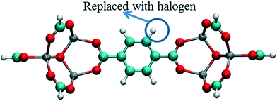 |
| | Fig. 3 Model IRMOF-1 cluster considered for dipole moment calculations with two metal nodes and a bridging ligand. The carbons of the carboxyl groups were terminated with hydrogens. Atom colors are same as per Fig. 1. | |
The effect of temperature
The behavior of the ligand rotation at room temperature is very important considering that any nanofluidic application is likely to happen at or near room temperature. However, at higher temperatures controlling the rotation of the ligand is expected to be more difficult due to fluctuations caused by the increased thermal energy. To study this effect, MD simulations of IRMOF-1-Cl were performed at 300 K using a 8 V nm−1 E-field and rotational dihedral angle distributions obtained are compared with those obtained at 100 K (Fig. 4). At 100 K (Fig. 4a), the distributions and the distinct peaks show that, both before and after the E-field applied (i.e. after the ligand rotated), rotational fluctuations are less compared to those observed at 300 K (Fig. 4b), where the distributions overlap with no distinct peaks observed. That is, after applying E-field at 300 K the IRMOF-1-Cl ligands rotate but they are not stable, i.e. large fluctuations.
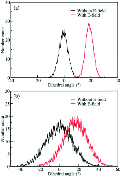 |
| | Fig. 4 Distribution of rotational dihedral angles of ligands in IRMOF-1-Cl at a) 100 K and b) 300 K with and without E-field (8 V nm−1). | |
The effect of ligand size
In order to reduce rotational fluctuations and achieve stable orientation for ligands after rotation under the E-field at room temperature, another IRMOF structure with a larger ligand, IRMOF-7, was considered. Besides, the IRMOF-1 ligand is too small to hinder the passage of molecules in the pores. Therefore, IRMOF-7 is expected to give more control over the rotation of the ligand as well as enable the opening and closing of the pore. IRMOF-7 exhibits two conformational isomers with coplanar and orthogonal carboxylate planes. This phenomenon was investigated in detail by Amirjalayer et al.45 In this study the orthogonal structure was considered. With the IRMOF-7 ligand, again Cl functionalization resulted in dipole moments in comparison to F and Br functionalized ligands (see Table S1†) for the model IRMOF-7 cluster shown in Fig. 5. In order to test the rotational stability of the IRMOF-7-Cl ligands at room temperature, MD simulations were conducted at 300 K with and without an E-field (5 V nm−1). Rotational dihedral angles of Cl functionalized IRMOF-7 ligands were again quantified using the same atoms shown in Fig. 1a. The distribution of rotational dihedral angles of the IRMOF-7-Cl ligands and their mean value as a function of MD simulation time are shown in Fig. 6.
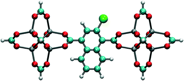 |
| | Fig. 5 Model IRMOF-7 cluster considered for dipole moment calculations with two metal nodes and a bridging ligand. The carbons of the carboxyl groups were terminated with hydrogens. Cl substitution, shown by the green atom, gave the largest dipole. | |
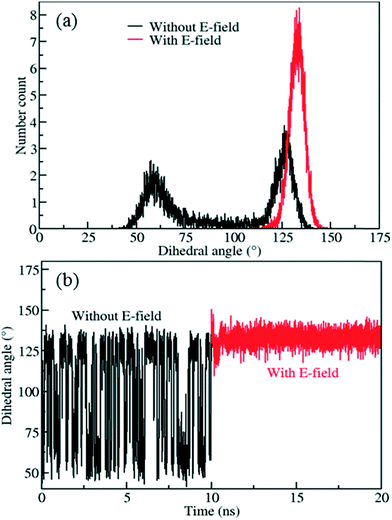 |
| | Fig. 6 a) Distribution of rotational dihedral angle of IRMOF-7-Cl ligands and b) their mean values as a function of time at 300 K with and without E-field (5 V nm−1). | |
The distribution obtained without the E-field (Fig. 6a, black line) peaks around 60° and 125° with roughly equal probabilities. This indicates that the ligands fluctuate between these two orientations due to the thermal energy at 300 K. This is also apparent from the mean value of the rotational dihedral angle shown in Fig. 6b (black line) as a function of MD simulations time. In contrast after the E-field is turned on the ligand in Fig. 6a (red line) and remains in a stable orientation during the rest of the MD simulation (Fig. 6b, red line). Indeed, these results show that using a larger ligand reduces the rotational fluctuations of the Cl functionalized ligands at room temperature under E-field. More importantly, using a larger ligand enables rotation of the ligand at a lower E-field strength and provides the opportunity to block or allow access to the pores of IRMOF-7. Double functionalization of IRMOF-7 ligand with Cl was considered because an increase in number of Cl substitutions is anticipated to increase the dipole moment and enable rotation of the ligand at lower E-field strengths. As the IRMOF-7 ligand is large there are many possible combinations for Cl substitution.
The effect of double halogenation
To screen these combinations DFT calculations were carried out using the cluster model shown in Fig. 7. Computed dipole moments for the different combinations of Cl substitutions are compared in Table 1. Among these, three combinations which gave the highest dipole moments, CR0–CR1, CR2–CR2p and CR0–CR0p, were chosen for MD simulations at 300 K to explore their rotational behavior under 2 V nm−1 E-field, which is less than the one applied in the case of CR0–CR0p substituted IRMOF-7-Cl2 structures are compared in Fig. 8. The results are very interesting. Both CR2–CR2p and CR0–CR0p substituted IRMOF-7-Cl2 ligands rotate by about single Cl functionalized IRMOF-7 ligands (Fig. 6).Distribution of the rotational dihedral angles of CR0–CR1, CR2–CR2p and 90° after the E-field is applied (Fig. 8a and b) which proves that increasing the dipole moment of the ligand by a second Cl substitution indeed reduces the E-field strength required for rotation. On the other hand, despite having the highest dipole moment, CR0–CR1 substituted IRMOF-7-Cl2 ligands show only around 20° rotation under the E-field (Fig. 8c). This is because the CR0 and CR1 substitution sites are located on opposite sides of the ligand axis and therefore dipole moment vector created does not contribute rotation around the axis of the ligand as much as it does for the cases in CR2–CR2p and CR0–CR0p substituted IRMOF-7-Cl2. Finally, MD simulations carried out with CR0–CR0p and CR2–CR2p substituted IRMOF-7-Cl2 structures at 300 K and applying a 1 V nm−1 E-field show that the rotation of the ligands in this case was around 90° and 15°, respectively (Fig. S1†). It is apparent that 1 V nm−1 is not sufficient to rotate the CR2–CR2p substituted IRMOF-7-Cl2 ligand. In case of CR0–CR0p substituted IRMOF-7-Cl2 ligand; however, the Cl atoms and the carboxylate O atoms are closer to each other compared to the case in CR2–CR2p substituted IRMOF-7-Cl2. Therefore, the steric and electrostatic repulsion between the Cl and the O atoms in the CR0–CR0p substituted IRMOF-7-Cl2 help the ligands rotate, requiring a lower E-field strength for rotation. We further show that the CR0–CR0p substituted IRMOF-7-Cl2 can be rotated by 90° even at 0.5 V nm−1 E-field strength (Fig. S2†).
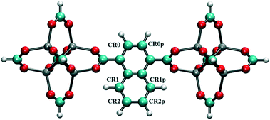 |
| | Fig. 7 Model IRMOF-7 cluster with two metal nodes and a bridging ligand considered for dipole moment calculations of double Cl substitution. The carbons of the carboxyl groups were terminated with hydrogens. Atom colors are as per Fig. 1. | |
Table 1 Dipole moments of double Cl substituted IRMOF-7 ligands with different substitution locations as shown in Fig. 7
| Positions of Cl substitutions |
Dipole moment (D) |
| CR0–CR0p |
2.4763 |
| CR1–CR1p |
0.4706 |
| CR2–CR2p |
2.5904 |
| CR0–CR1 |
2.9346 |
| CR0–CR1p |
2.1622 |
| CR0–CR2 |
1.1744 |
| CR0–CR2p |
0.6518 |
| CR1–CR2 |
2.4637 |
| CR1–CR2p |
1.4615 |
 |
| | Fig. 8 Rotational dihedral angle distributions of (a) CR2–CR2p (b) CR0–CR0p and (c) CR0–CR1 substituted IRMOF-7-Cl2 structures at 300 K under E-field (2 V nm−1). | |
It should be noted that though if the IRMOF-7 isomer with the coplanar carboxylate planes were used in our simulations the E-field required for rotating the ligands would have been different.
Controlling the direction of flow
To demonstrate control of fluid flow by rotating MOF ligands under an E-field, methane molecules were loaded in to CR0–CR0p substituted IRMOF-7-Cl2 by carrying out a GCMC simulation at 300 K and 20 atm. This was then followed by MD simulations conducted with and without the presence of an E-field (2 V nm−1). To study the dynamic behaviour of methane within the pores of CR0–CR0p substituted IRMOF-7-Cl2 MSD for the methane molecules has been calculated in x, y and z directions separately before and after the E-field applied and compared in Fig. 9. When no E-field applied, MSD of the methane molecules in the x, y and z-directions are almost same (Fig. 9a). This shows that the diffusion is roughly uniform in all three directions. On the other hand, after applying the E-field, MSD of methane molecules increase in the x-direction, decrease in the y direction and do not change in the z-direction (Fig. 9b). These observations can be explained by comparing the snapshots obtained before and after the E-field applied (Fig. 10, S3 and S4†). The mobility of the molecules in the x-direction increases because after the E-field is applied ligands which were initially restricting the diffusion of methane in the x-direction (Fig. 10a) rotate by about 90° and allow a clear diffusion path (Fig. 10b). On the other hand, rotation of the ligands after the E-field is applied largely blocks the path of methane molecules in the y direction (Fig. S3†). More interestingly, the mobility of methane molecules in the z-directions does not show any appreciable change despite the rotation of ligands. A close look up to the snapshots (Fig. S4†) reveal that ligands initially restricting the methane diffusion of methane in the z direction rotate by 90°, but then this effect is neutralized by the rotation of other set of ligands to now hinder the diffusion of methane molecules. Finally, the enhancement of the diffusion of the molecules in the x direction is fully reversible. As shown in Fig. S5,† by applying an electric field in the y direction the ligands can be rotated back by 90°, to their original positions and the MSD in the x direction is restored to its previous value. Indeed, controlled rotation of MOF ligands under an E-field to direct the flow of molecules resonate with the molecular traffic control concept proposed in nanoporous materials and may be used for achieving similar effects.46–49
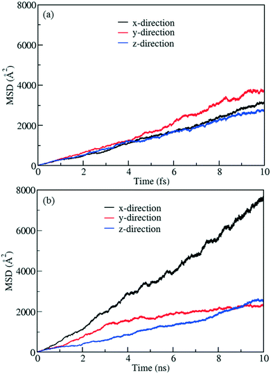 |
| | Fig. 9 MSD profiles for methane in methane filled CR0–CR0p substituted IRMOF-7-Cl2 (a) without E-field and (b) with E-field (2 V nm−1). | |
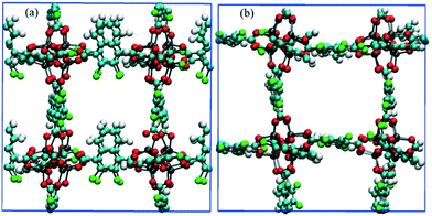 |
| | Fig. 10 Snapshots of CR0–CR0p substituted IRMOF-7-Cl2 in the x-direction obtained from methane diffusion simulations (a) before and (b) after the E-field (2 V nm−1) is applied. Methane molecules are not shown for clarity. | |
Conclusions
We computationally designed E-field responsive MOFs by halogenating the organic ligands in IRMOF-1 and 7 in order to enhance or restrict the diffusion of molecules. This was achieved by controlled rotation of the ligands under the effect of an E-field. The Cl functionalized ligands in IRMOF-1 exhibited around 25° rotation in MD simulations conducted at 100 K and under 8 V nm−1 E-field, which was larger than the rotation observed for F and Br functionalized ligands. This was corroborated using DFT computed dipole moments for Cl, F and Br functionalized ligands which showed that Cl functionalization yielded a greater dipole moment. Cl functionalization of IRMOF-7 ligands, which are larger than those in IRMOF-1, proved to be a very good strategy for controlled rotation of ligands under an E-field. Using larger ligands not only reduced the rotational fluctuations and allowed stable ligand orientation after the E-field applied at room temperature but also provided the opportunity to hinder the diffusion of molecules in a certain direction. DFT computed dipole moments and MD simulation results confirmed that double Cl functionalization and the optimization of the Cl substitution locations in IRMOF-7 ligands reduced the E-field strength required to rotate the ligand to as low as 0.5 V nm−1. The optimized substitution locations of Cl functionalization were found to be the hydrogens closest to the O atoms of the carboxylate group. This is because the steric and the electrostatic repulsion between the Cl atoms of the ligand and the O atoms helped the ligands rotate. The computed MSD profiles for the methane molecules in the CR0–CR0 substituted IRMOF-7-Cl2 confirmed the flow enhancement in applied E-field direction and flow restriction in other directions. The rotation of the ligands induced by the E-field and the consequent enhancement of the methane diffusion were shown to be reversible by changing the direction of the E-field applied. For nanofluidic applications the control of fluid behavior is of paramount importance. Our study reveals the possibility of using MOF materials to control fluid flow without using mechanical parts in nanofluidic devices based on an E-field induced molecular gating mechanism.
Conflicts of interest
There are no conflicts of interest to declare.
Acknowledgements
The authors gratefully acknowledge funding from the Leverhulme Trust Project Grant RPG-2016-331 and the use of the UCL Grace High Performance Computing Facility (Grace@UCL), and associated support services, in the completion of this work.
References
- H.-C. Zhou, J. R. Long and O. M. Yaghi, Chem. Rev., 2012, 112, 673–674 CrossRef CAS PubMed.
- H. Furukawa, N. Ko, Y. B. Go, N. Aratani, S. B. Choi, E. Choi, A. Ö. Yazaydin, R. Q. Snurr, M. O'Keeffe, J. Kim and O. M. Yaghi, Science, 2010, 329, 424–428 CrossRef CAS PubMed.
- E. M. Dias and C. Petit, J. Mater. Chem. A, 2015, 3, 22484–22506 RSC.
- L. E. Kreno, K. Leong, O. K. Farha, M. Allendorf, R. P. Van Duyne and J. T. Hupp, Chem. Rev., 2012, 112, 1105–1125 CrossRef CAS PubMed.
- J. Lee, O. K. Farha, J. Roberts, K. A. Scheidt, S. T. Nguyen and J. T. Hupp, Chem. Soc. Rev., 2009, 38, 1450–1459 RSC.
- P. Horcajada, T. Chalati, C. Serre, B. Gillet, C. Sebrie, T. Baati, J. F. Eubank, D. Heurtaux, P. Clayette, C. Kreuz, J.-S. Chang, Y. K. Hwang, V. Marsaud, P.-N. Bories, L. Cynober, S. Gil, G. Férey, P. Couvreur and R. Gref, Nat. Mater., 2009, 9, 172 CrossRef PubMed.
- A. Schneemann, V. Bon, I. Schwedler, I. Senkovska, S. Kaskel and R. A. Fischer, Chem. Soc. Rev., 2014, 43, 6062–6096 RSC.
- F.-X. Coudert, Chem. Mater., 2015, 27, 1905–1916 CrossRef CAS.
- Z. Zou, S. Li, D. He, X. He, K. Wang, L. Li, X. Yang and H. Li, J. Mater. Chem. B, 2017, 5, 2126–2132 RSC.
- A. B. Kanj, K. Müller and L. Heinke, Macromol. Rapid Commun., 2018, 39, 1700239 CrossRef PubMed.
- Z. Chang, D.-H. Yang, J. Xu, T.-L. Hu and X.-H. Bu, Adv. Mater., 2015, 27, 5432–5441 CrossRef CAS PubMed.
- A. Ghoufi, K. Benhamed, L. Boukli-Hacene and G. Maurin, ACS Cent. Sci., 2017, 3, 394–398 CrossRef CAS PubMed.
- B. Tam and O. Yazaydin, J. Mater. Chem. A, 2017, 5, 8690–8696 RSC.
- A. Knebel, B. Geppert, K. Volgmann, D. I. Kolokolov, A. G. Stepanov, J. Twiefel, P. Heitjans, D. Volkmer and J. Caro, Science, 2017, 358, 347 CrossRef CAS PubMed.
- P. Abgrall and N. T. Nguyen, Anal. Chem., 2008, 80, 2326–2341 CrossRef CAS PubMed.
- A. A. Yanik, M. Huang, A. Artar, T.-Y. Chang and H. Altug, Appl. Phys. Lett., 2010, 96, 021101 CrossRef.
- J. Huang, Y. Wang and M. Laradji, Macromolecules, 2006, 39, 5546–5554 CrossRef CAS.
- A. van den Berg, H. G. Craighead and P. Yang, Chem. Soc. Rev., 2010, 39, 899–900 RSC.
- S. Takamizawa, Y. Takasaki and R. Miyake, J. Am. Chem. Soc., 2010, 132, 2862–2863 CrossRef CAS PubMed.
- Y. Takasaki and S. Takamizawa, J. Am. Chem. Soc., 2014, 136, 6806–6809 CrossRef CAS PubMed.
- S. P. Adiga and D. W. Brenner, Nano Lett., 2005, 5, 2509–2514 CrossRef CAS PubMed.
- S. P. Adiga and D. W. Brenner, Nano Lett., 2002, 2, 567–572 CrossRef CAS.
- R. Y. H. Lim and J. Deng, ACS Nano, 2009, 3, 2911–2918 CrossRef CAS PubMed.
- T. Suo and M. D. Whitmore, J. Chem. Phys., 2014, 140, 114902 CrossRef PubMed.
- L. Zhai, A. J. Nolte, R. E. Cohen and M. F. Rubner, Macromolecules, 2004, 37, 6113–6123 CrossRef CAS.
- A. Comotti, S. Bracco and P. Sozzani, Acc. Chem. Res., 2016, 49, 1701–1710 CrossRef CAS PubMed.
- N. C. Burtch, A. Torres-Knoop, G. S. Foo, J. Leisen, C. Sievers, B. Ensing, D. Dubbeldam and K. S. Walton, J. Phys. Chem. Lett., 2015, 6, 812–816 CrossRef CAS PubMed.
- E. B. Winston, P. J. Lowell, J. Vacek, J. Chocholousova, J. Michl and J. C. Price, Phys. Chem. Chem. Phys., 2008, 10, 5188–5191 RSC.
- S. Bracco, F. Castiglioni, A. Comotti, S. Galli, M. Negroni, A. Maspero and P. Sozzani, Chem. – Eur. J., 2017, 23, 11210–11215 CrossRef CAS PubMed.
- F. Moreau, D. I. Kolokolov, A. G. Stepanov, T. L. Easun, A. Dailly, W. Lewis, A. J. Blake, H. Nowell, M. J. Lennox, E. Besley, S. Yang and M. Schröder, Proc. Natl. Acad. Sci. U. S. A., 2017, 114, 3056 CrossRef CAS PubMed.
- M. Inukai, T. Fukushima, Y. Hijikata, N. Ogiwara, S. Horike and S. Kitagawa, J. Am. Chem. Soc., 2015, 137, 12183–12186 CrossRef CAS PubMed.
- S. T. Meek, J. J. Perry, S. L. Teich-McGoldrick, J. A. Greathouse and M. D. Allendorf, Cryst. Growth Des., 2011, 11, 4309–4312 CrossRef CAS.
- M. K. Taylor, T. Runčevski, J. Oktawiec, M. I. Gonzalez, R. L. Siegelman, J. A. Mason, J. Ye, C. M. Brown and J. R. Long, J. Am. Chem. Soc., 2016, 138, 15019–15026 CrossRef CAS PubMed.
- X.-L. Lv, K. Wang, B. Wang, J. Su, X. Zou, Y. Xie, J.-R. Li and H.-C. Zhou, J. Am. Chem. Soc., 2017, 139, 211–217 CrossRef CAS PubMed.
- M. Eddaoudi, J. Kim, N. Rosi, D. Vodak, J. Wachter, M. Keeffe and O. M. Yaghi, Science, 2002, 295, 469 CrossRef CAS PubMed.
-
J. C. Stewart, D. S. Matthew, J. P. Chris, J. H. Phil, I. J. P. Matt, K. Refson and C. P. Mike, First principles methods using CASTEP, 2005 Search PubMed.
- J. P. Perdew, K. Burke and M. Ernzerhof, Phys. Rev. Lett., 1996, 77, 3865–3868 CrossRef CAS PubMed.
- A. Tkatchenko and M. Scheffler, Phys. Rev. Lett., 2009, 102, 073005 CrossRef PubMed.
- C. Campañá, B. Mussard and T. K. Woo, J. Chem. Theory Comput., 2009, 5, 2866–2878 CrossRef PubMed.
-
M. J. Frisch, G. W. Trucks, H. B. Schlegel, G. E. Scuseria, M. A. Robb, J. R. Cheeseman, G. Scalmani, V. Barone, B. Mennucci, G. A. Petersson, H. Nakatsuji, M. Caricato, X. Li, H. P. Hratchian, A. F. Izmaylov, J. Bloino, G. Zheng, J. L. Sonnenberg, M. Hada, M. Ehara, K. Toyota, R. Fukuda, J. Hasegawa, M. Ishida, T. Nakajima, Y. Honda, O. Kitao, H. Nakai, T. Vreven, J. J. A. Montgomery, J. E. Peralta, F. Ogliaro, M. Bearpark, J. J. Heyd, E. Brothers, K. N. Kudin, V. N. Staroverov, T. Keith, R. Kobayashi, J. Normand, K. Raghavachari, A. Rendell, J. C. Burant, S. S. Iyengar, J. Tomasi, M. Cossi, N. Rega, J. M. Millam, M. Klene, J. E. Knox, J. B. Cross, V. Bakken, C. Adamo, J. Jaramillo, R. Gomperts, R. E. Stratmann, O. Yazyev, A. J. Austin, R. Cammi, C. Pomelli, J. W. Ochterski, R. L. Martin, K. Morokuma, V. G. Zakrzewski, G. A. Voth, P. Salvador, J. J. Dannenberg, S. Dapprich, A. D. Daniels, O. Farkas, J. B. Foresman, J. V. Ortiz, J. Cioslowski and D. J. Fox, Gaussian 09 (Revision B.01), Gaussian, Inc., Wallingford, CT, 2010 Search PubMed.
- S. Plimpton, J. Comput. Phys., 1995, 117, 1–19 CrossRef CAS.
- D. Dubbeldam, K. S. Walton, D. E. Ellis and R. Q. Snurr, Angew. Chem., Int. Ed., 2007, 46, 4496–4499 CrossRef CAS PubMed.
- C. J. Casewit, K. S. Colwell and A. K. Rappe, J. Am. Chem. Soc., 1992, 114, 10035–10046 CrossRef CAS.
- J. J. Potoff and J. I. Siepmann, AIChE J., 2001, 47, 1676–1682 CrossRef CAS.
- S. Amirjalayer and R. Schmid, J. Phys. Chem. C, 2008, 112, 14980–14987 CrossRef CAS.
- A. Brzank, G. M. Schütz, P. Bräuer and J. Kärger, Phys. Rev. E: Stat., Nonlinear, Soft Matter Phys., 2004, 69, 031102 CrossRef CAS PubMed.
- A. Brzank and G. Schütz, Appl. Catal., A, 2005, 288, 194–202 CrossRef CAS.
- E. G. Derouane and Z. Gabelica, J. Catal., 1980, 65, 486–489 CrossRef CAS.
- L. A. Clark, G. T. Ye and R. Q. Snurr, Phys. Rev. Lett., 2000, 84, 2893–2896 CrossRef CAS PubMed.
Footnote |
| † Electronic supplementary information (ESI) available: Results from dipole moment calculations, rotational dihedral angle distributions, MSD profiles of methane and snapshots from simulations. See DOI: 10.1039/c8me00030a |
|
| This journal is © The Royal Society of Chemistry 2018 |
Click here to see how this site uses Cookies. View our privacy policy here.  Open Access Article
 and
A. Ozgur
Yazaydin
 *
*

![[thin space (1/6-em)]](https://www.rsc.org/images/entities/char_2009.gif) sin
sin![[thin space (1/6-em)]](https://www.rsc.org/images/entities/char_2009.gif) (θ)
(θ)


