
 Open Access Article
 This Open Access Article is licensed under a
 Creative Commons Attribution 3.0 Unported Licence
Challenges and opportunities for the utilisation of ionic liquids as solvents for CO2 capture
Maria T.
Mota-Martinez
 abc,
Patrick
Brandl
bc,
Jason P.
Hallett
a and
Niall
Mac Dowell
*bc
abc,
Patrick
Brandl
bc,
Jason P.
Hallett
a and
Niall
Mac Dowell
*bc
aDepartment of Chemical Engineering, Imperial College London, Exhibition Road, London, SW7 2AZ, UK
bCentre for Process Systems Engineering, Imperial College London, Exhibition Road, London, SW7 2AZ, UK. E-mail: niall@imperial.ac.uk; Tel: +44 (0)20 7594 9298
cCentre for Environmental Policy, Imperial College London, Exhibition Road, London, SW7 1NA, UK
First published on 10th May 2018
Abstract
Ionic liquids have been extensively investigated as promising materials for several gas separation processes, including CO2 capture. They have the potential to outperform traditional solvents, in terms of their capacity, selectivity, regenerability and stability. In fact, hundreds of ionic liquids have been investigated as potential sorbents for CO2 capture. However, most studies focus on enhancing equilibrium capacity, and neglect to consider other properties, such as transport properties, and hence ignore the effect that the overall set of properties have on process performance, and therefore on cost. In this study, we propose a new methodology for their evaluation using a range of monetised and non-monetised process performance indices. Our results demonstrate that whilst most research effort is focused on improving CO2 solubility, viscosity, a transport property, and heat capacity, a thermochemical property, might preclude the use of ionic liquids, even those which are highly CO2-philic, and therefore increased effort on addressing the challenges associated with heat capacity and viscosity is an urgent necessity. This work highlights a range of potential challenges that ionic liquids will face before they can be applied at process scale, and identifies some key research opportunities.
Design, System, ApplicationThere have been many studies focused on the utilisation of ionic liquids (ILs) for CO2 capture from exhaust gases, with the majority focused on the potential for superior performance of ILs in terms of their CO2 absorption capacity, or reduced thermal energy required for regeneration. However, relatively little has been made of the implications for process design and therefore cost associated with the increased viscosity, or the necessity for operating at elevated pressure and therefore of the trade-off between reduced heat for increased work requirements. In this contribution, we evaluate the impact of the structure of ILs on their process performance, and illustrate how a trend towards increasing CO2 solubility by increasing functionalization has, at best, kept process performance at constant owing to an increased solvent viscosity arising from the additional functionalisation. This has had the effect of rendering ILs effectively inapplicable in this context. We finally present IL synthesis insights derived from our process modelling work, and use this to identify priorities for future efforts in the design and synthesis of ILs for gas separations. |
1 Introduction
Ionic liquids (ILs) have been known for over a century. The first work which reports an ionic liquid was published in 1888, when measured the melting point of ethanolammonium nitrate.1 But it is the synthesis of the low melting ethylammonium nitrate ionic liquid by in 1914 the work which is usually recognised as the first publised study on ionic liquids.2 However, the focus on ionic liquids only emerged after Seddon,3 Freemantle4,5 and Huddleston and Rogers6 identified them as promising solvents for clean technologies. Until 1997, only 432 articles on ionic liquids were published. The total number of publications has rapidly increased to 84![[thin space (1/6-em)]](https://www.rsc.org/images/entities/char_2009.gif) 000 by the end of 2017, according to ISI Web of Knowledge, and almost 10000 patents on ionic liquids have been filed up to the time of writing.
000 by the end of 2017, according to ISI Web of Knowledge, and almost 10000 patents on ionic liquids have been filed up to the time of writing.
Clearly, there has been a substantial investment in research for the applications of ionic liquids. Ionic liquids have been investigated as solvents for organic catalysis,7 in the food industry,8 nuclear waste treatment,9 lubrication, energy storage,10,11 electrochemistry,12 and separation operations, including as entrainer in liquid–liquid extraction6,13 and in extractive distillation,14 pretreatment of biomass,15,16 metal extraction,17–19 and gas separation.20,21 Despite this extensive research effort to develop these applications, a limited number of them have been successfully transferred to industrial scale. These include BASF's BASIL™ (biphasic acid scavenging utilizing ionic liquids) process22 or Eastman Chemical Company's isomerisation of 3,4-epoxybut-1-ene to 2,5-dihydrofuran.23 The elevated cost of ionic liquids is one of main impediments for the implementation of ionic liquids at industrial scale. Whilst this is a legitimate concern, it is also true that it is possible to synthesise inexpensive ionic liquids.24 With many tens of thousands of ionic liquids already in existence, and the potential for the synthesis of millions,25 discriminating between candidate ILs presents a significant challenge. Given that the thermophysical properties of ILs can be “tuned” by the combination of anions and cations,4 developing an approach for the rational selection and design of ILs for a specific application is a key research gap.
Eisinger and Keller conducted a similar study for ILs that undergo a liquid–solid phase change, however their economic assessment relies on vendor quotes.26 Zhai and Rubin published a cost breakdown for [P66614][2-CNpyr],27 Shiflett et al., for 1-butyl-3-methylimidazolium acetate ([C4C1im][Ac]),28 Khonkaen et al., for 1-ethyl-3-methylimidazolium acetate ([C2C1im][Ac]),29 Ma et al., for 1-butyl-3-methylimidazolium tetrafluoroborate ([C4C1im][BF4]) and 1-butyl-3-methylimidazolium hexafluorophosphate ([C4C1im][PF6]),30 and de Riva for selected ILs.31 Jongpitisub et al., analysed the impact of heat integration on the process costs for [C2C1im][Ac].32 Xie et al., published the energy consumption of imidazolium-based ILs without reporting costs.33
One of the most active research areas in ionic liquid technology is their use as solvents for CO2 capture. Thousands of studies have been completed on this topic and more than 100 ionic liquids have been proposed as promising solvents. This study aims to identify the challenges and opportunities for the deployment of ionic liquids as solvents for carbon capture. We have developed a mathematical model which assesses the process performance of ionic liquids for carbon capture based on a range of key process indicators (KPI's) including process design and cost.
The remainder of this paper is structured as follows: section 2 explores the advances on ionic liquids as solvents for CO2 capture. Section 3 presents the process model and the methodological evaluation of the process performance of ionic liquids as solvents for CO2 capture. Section 4 analyses the results in the effect of the selected indicators on the characteristics of the solvent and the flue gas. Finally, section 5 presents the conclusions of our work and some final remarks.
2 Ionic liquids as solvents for CO2 capture
The most remarkable property which makes these solvents attractive for numerous processes, including gas separation, is their negligible vapour pressure.34,35 The use of non-volatile solvents is particularly interesting for CO2 capture to prevent solvent loss and thus to mitigate the environmental concerns associated to the use of traditional volatile solvents such as ethanolamines.36 In addition, ionic liquids are highly chemically and thermally stable.37 At least 32000 articles have been published in the area of ionic liquid-based CO2 capture, and whilst we do not intend to exhaustively review this literature here, we do aim to critically assess some key contributions.
The work of Blanchard et al. in 1999, where the high solubility of CO2 in l-ethyl-3-methylimidazolium hexafluorophosphate ([C6C1im][PF6]) ionic liquid is discussed,38 is broadly considered to have catalysed this research field. Interestingly, the advancement in the research on the capacity of ionic liquids came in waves as new anions were developed. During the first five years of the twenty-first century, the CO2 solubility of the first generation of inorganic fluorine-containing anions, i.e., [PF6−] (ref. 39–50) and [BF4−],39,45,48,49,51,52 was determined. As fluorine-containing ionic liquids were found to have a significant affinity for CO2, other organic fluoroalkyl anions were tested the following years; [Tf2N−],45,46,49,53–56 and [OTf−].45,57 However, fluorine-containing ionic liquids could potentially react with water, forming hydrofluoric acid, which is highly corrosive. This is particularly inconvenient for treating exhaust gases arising from combustion processes, which can contain as much as 10% water. Subsequently, another type of ionic liquids emerged: the cyano-based ionic liquids. Although [C2C1im][N(CN)2] had attracted the attention of researchers during the first wave,45,46 it was not until 2010 when attention was truly focused on this family of ionic liquids owing to their high CO2 solubility58,59 and relatively low viscosity.60,61 In addition to the [N(CN)2]−, [B(CN)4]− (ref. 58 and 62) and [C(CN)3]− (ref. 63 and 64)-based ionic liquids have been extensively studied. However, very few of these studies evaluated ionic liquids as potential solvents for carbon capture from a process engineering perspective.
3 Model development
Building on previous work,65 we have developed a modelling tool for the rapid screening of ionic liquids on the basis of their process performance and cost. The model uses an archetypal physical absorption process topology, illustrated in Fig. 1. Our process includes an up-front compression train for the exhaust gas, which is typically available at low pressure. However, most ionic liquids are physical solvents, thus their absorption capacity increases with pressure.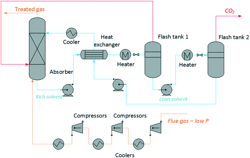 | ||
| Fig. 1 Process flow diagram of an archetypal CO2 capture plant using ionic liquids. | ||
The regeneration of the solvent is achieved by a combined temperature and pressure swing. Two regeneration steps are required to ensure that the CO2 stream is suitable for transport and storage, i.e., the concentration of other gases and impurities is below 5%.66 The other dissolved gases in the ionic liquid are stripped out of the solvent in the first regeneration step. The desorption of CO2 occurs essentially in the second step.
The size of each of the process units, and the heating, cooling and electric requirements are estimated based on the mass and heat transfer properties of the ionic liquids. The model calculates non-monetised and monetised key process indicators (KPI's) as basis for the assessment of the ionic liquids. The non-monetised indicators include the height of the absorption column, the area of the heat exchangers, and the heat and work requirements of the process. The monetised indices include the annualised capital expenditure (CAPEX), operating expenditure (OPEX), and total annual cost (TAC).
3.1 Absorption
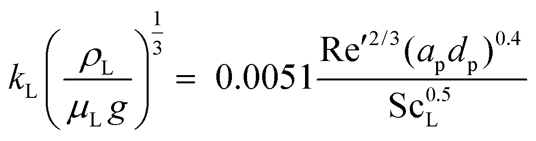
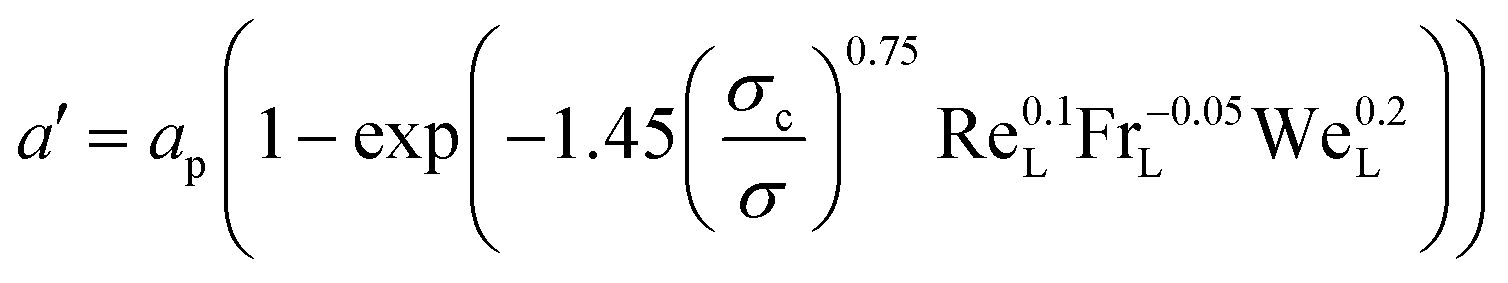
The absorption column is represented as a rate-based adiabatic packed column. The model comprises the mass and energy balances, the equilibrium relations, and the rate equations required to describe mass transfer.| vinyini − nabsi = voutyouti | (1) |
Interphase mass transfer has been described using the two-film theory.67 Phase equilibrium is assumed in the vapour–liquid interface. In cases where the absorption occurs at low pressure, it is assumed that Henry's law is obeyed, i.e., the molar fraction of the solute in the liquid interface with the physical solvent (x0,Ii). Therefore, the equilibrium is calculated as:
| yIi = Hix0,Ii | (2) |
 | (3) |
 | (4) |
 | (5) |
| NCO2 = JCO2εa′ACSZT | (6) |
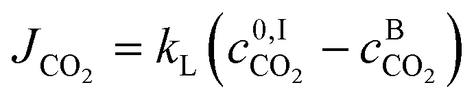
The molar flux of CO2 in the interface JCO2 is calculated using:
 | (7) |
 | (8) |
 | (9) |
 | (10) |
3.2 Heat exchangers
The process model includes three gas coolers in the flue gas compression stage, and four heat exchangers, i.e., the lean-rich heat exchanger, two heaters and the lean cooler. In all cases they have been modelled as shell-and-tube units. The general equation for sizing a heat exchanger is:| Q = UAHEΔTLM | (11) |
 | (12) |
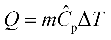
The heat rate in a heat exchanger is given by the sensible heat:
 | (13) |
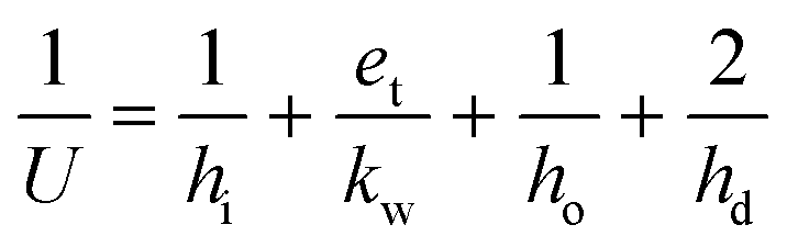
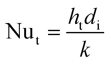
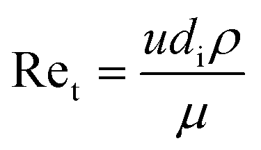
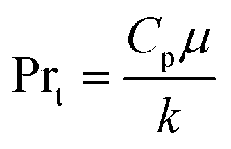
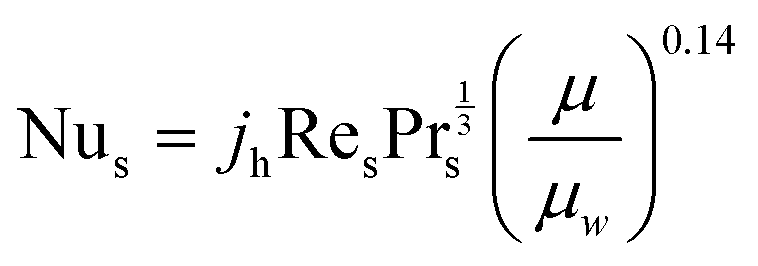
The heat transfer coefficient value depends on the flow regimes, which is a function of the heat exchanger internals and arrangements and on the fluid properties. For turbulent flow, the heat transfer coefficient for the inside fluid has been estimated via:
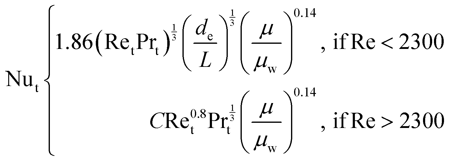 | (14) |
 | (15) |
 | (16) |
 | (17) |
The heat transfer coefficient of the shell side is calculated using the Kern's method:71
 | (18) |
3.3 Compression
Compressors are widely assumed to adiabatic73 and their power demand WComp is calculated by: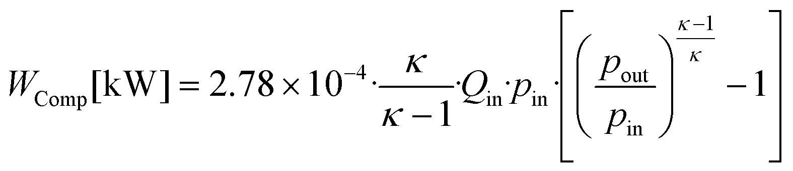 | (19) |
3.4 Economic indices
A key objective of this work is to relate the cost of the carbon capture plant to the properties of the ionic liquids. Our model uses the total annualised cost (TAC) as the index against which to assess the economic performance of the plant: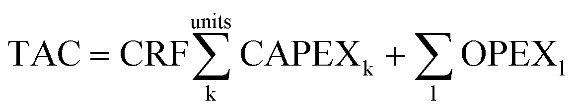 | (20) |
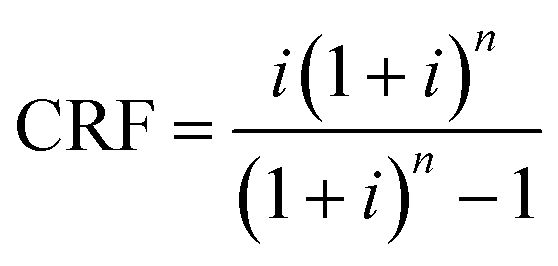 | (21) |
The capital cost, CAPEX, for each unit has been estimated using correlations that link the cost to key properties of the unit.74 For example, the installed cost of a heat exchanger CHX is estimated based on the heat transfer area AHX, as given in eqn (22):
| CHX = 1.218(fdfmfpCb)CI | (22) |
| Cb = exp[8.821 − 0.30863(lnAHX) + 0.0681(lnAHX)2] | (23) |
Similarly, the installed cost of the packed column is given by:
| Cabs = 1.281[f1Cb + VpCp + Cp1]CI | (24) |
| Cb = 1.218exp[6.629 + 0.1826(lnW)] + 0.02297(lnW)2] | (25) |
The weight of the shell is calculated from column size. In this work, a thickness of 2 mm was assumed. The product VpCp refers to the cost of column internals, where Vp is the volume of packing required and Cp refers to the specific cost of the packing used. Vp is directly calculated via the column sizing equations. Cp is assigned a value of $76.6 ft−3 which is representative of the cost of the packing used in this work. Cp1 is the cost of the absorption shell given by:
| Cp1 = 300D0.7396Z0T·7068 | (26) |
The costs associated with the compression CComp are calculated by the costs of one 30000 HP compressor Cl-Comp multiplied by the required number NComp of compressors. Couper74 gives the number of compressors as
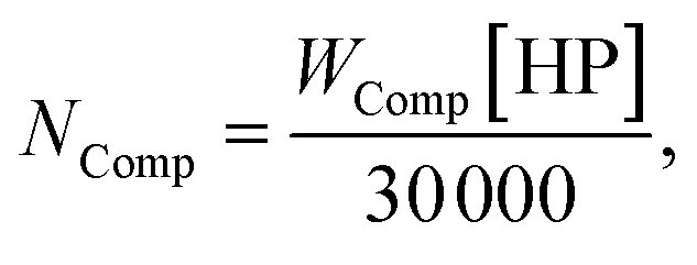 | (27) |
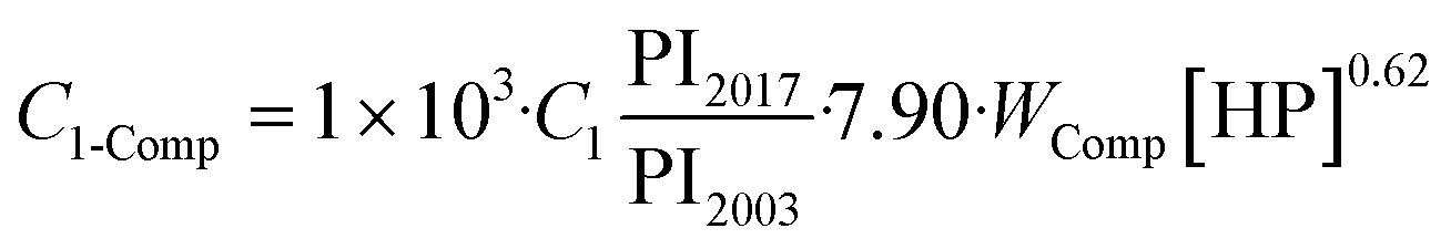 | (28) |
The total costs associated with the compression CComp are then given by:
| CComp = C1-Comp·NComp | (29) |
The main operating costs are those derived from the electricity consumption and from the heat requirements. The short-run marginal cost (SRMC) of electricity has been calculated assuming a price of coal of $50/tcoal.75,76 The cost of steam has been estimated using the SRMC assuming that the efficiency of the boiler is 90%. Given that ionic liquids are very low volatile liquids,35,77 and chemically stable compounds, we assume that only 10% of the solvent is replaced annually. A conservative estimate of the cost of a bulk ionic liquid has been set to $10 per kg. The annualised costs, i.e., annual CAPEX, OPEX and TAC, are given in tonnes of CO2 captured in one year. The costs associated to the compression of the CO2 for transport and storage have not been included in this work. A previous study shows that the cost of CO2 compression and dehydration is on the order of $20–25/tCO2.66
4 Results and discussion
We applied our methodology to evaluate the process performance of the ionic liquids solvents in an archetypal carbon capture plant treating 900 kg s−1 of flue gas containing 12% (v/v) of CO2 from an 800 MW supercritical pulverised coal power plant (ScPC). We assume that the plant runs for 335 days per year at 100% capacity. The model establishes that capture rate is at least 90% of the carbon emitted by the power plant and that the content impurities (H2O, N2, etc.) in the CO2-rich stream sent to compression is less than 5%.We selected the height of the absorber and the heat and power requirements as non-monetised KPI's, and the capital and operating costs as monetised KPI's. These indices are a function of the thermo-physical and phase equilibrium properties of the ionic liquid. We have identified the minimum set of properties required to evaluate the ionic liquids using our methodology. These are:
• Henry's coefficient
• Viscosity
• Density
• Heat capacity
• Thermal conductivity
• Surface tension
We found that whilst over a hundred ionic liquids have been suggested as promising solvents for CO2 capture, less than 30 have the full range of properties reported in the literature. Unless all the properties indicated above are reported at the relevant range of temperature and compositions, the process performance of solvents for carbon capture can only be approximated, at the very most, when not unlikely to be assessed. Therefore, we have selected only those ionic liquids which have been fully characterised in the literature to be evaluated using the methodology presented herein.
4.1 Process design
The temperature and pressure at which the CO2 is absorbed and desorbed are design parameters in the capture plant. Given that physical solvents such as the ionic liquids considered here follow Henry's law until moderate pressures, we assume that the CO2 capacity increases almost linearly with pressure. Compressing the flue gas to higher pressures obviously implies higher electricity consumption in the compressors. Consequently, it is frequently claimed that the higher the pressure, the higher the operating costs. However, Fig. 2 shows that, in fact, the overall costs are significantly reduced at higher pressure. A lower solvent flow rate driven by higher CO2 absorption by the ionic liquid leads firstly to smaller process units, reducing the capital costs, and secondly to lower heating and cooling requirements, reducing the operating costs, despite the higher compression costs. Fig. 3 shows the contrasting effect on the cost associated to electric consumption of the plant, which obviously increases with pressure, and the cost associated to the generation of steam, which considerably decreases. | ||
| Fig. 2 Effect of the absorption pressure on the annualised CAPEX and OPEX. | ||
 | ||
| Fig. 3 Effect of the absorption pressure on the cost of electric and heating power. | ||
Based on the results presented in Fig. 2, we have selected 20 bars to run the screening of the ionic liquids, which represents a trade-off pressure between the costs of the carbon capture plant and the electric consumption. The heights of the absorber for CO2 separation using 15 different ionic liquids are illustrated in Fig. 4. The ionic liquid which requires the shortest absorption tower is 1-ethyl-3-methylimidazolium dicyanamide ([C2C1im][N(CN)2]), which is a low viscosity ionic liquid with high CO2 absorption capacity; two advantageous properties. In fact, it is the only ionic liquid which requires a lower height than the tallest process columns in the world‡ and ILs which require a taller column will likely not be deployed on industrial scale.
 | ||
| Fig. 4 Heights of the CO2 absorbers using 15 ionic liquids as solvents at 20 bars and 303 K. They are compared to the tallest process column (121.3 m),‡ the Petronas towers (451.9 m),§ and the Burj Khalifa tower (828 m).§ | ||
4.2 Cost evaluation
We select the four most suitable ionic liquids according to the non-monetised results shown in Fig. 4, i.e., [C2C2im][N(CN)2], [C2C2im][NTf2], [C2C2im][C(CN)3] and [C2C2im][BF4], and a medium performing ionic liquid, i.e., [C6C2im][B(CN)4], to further evaluate their economic and process performance according to the selected monetised key parameters.The total cost per tonne of CO2 of the selected ionic liquids is broken down into CAPEX and OPEX and compare to those costs of the benchmark (30% MEA) in Fig. 5. It is obvious from our results that the cost of the capture plant using ionic liquids is higher than the cost of the benchmark. The TAC of a capture plant using the benchmark solvent is $51/tCO2,¶65 whereas the lowest cost using an ionic liquid is $90/tCO2 for [C2C1im][N(CN)2]. Despite both [C4C1im][C(CN)3] and [C6C1im][B(CN)4] being low viscosity ionic liquids,62,81 the cost of the capture plant using [C2C1im][N(CN)2] is greater because of its reduced CO2 capacity. However, as illustrated previously in Fig. 4, [C6C1im][B(CN)4], which is more viscous than [C4C1im][C(CN)3], requires an absorption tower which is 23% higher. Therefore, an ionic liquid which could have been dropped out of the selected candidate list based on non-monetised metrics (height of the absorption column) is found to have better economic performance. On the other hand, technical challenges might prevent the construction of such a column. The selection, consequently, must not be based on neither non-monetised nor monetise KPI's by themselves, but a rational evaluation of both.
 | ||
| Fig. 5 Cost per tonne of CO2 using 5 ionic liquids as solvent for CO2 capture. | ||
The capital cost of the main process units is shown in Fig. 6. Whilst the absorber is frequently considered the most expensive unit in a CO2 capture plant when aqueous alkanolamines are used,83Fig. 6 shows that the cost of the conventional shell and tube heat exchanger is two orders of magnitude higher than the cost of the absorber. Ionic liquids are in most cases moderately viscous fluids, with viscosities ranging from 10 to 10000 Pa s, although most of the conventional ionic liquids considered for CO2 capture present viscosities below 500 Pa s.21 All the selected ionic liquids have a viscosity below 150 Pa s at the working conditions. Yet, this viscosity is high enough to significantly effect the hydrodynamics of the solvent in the different units of the plant, and therefore their size. Heat exchangers are particularly affected by higher viscosities and coolers by the solvent's flowrate and heat capacity, as was demonstrated in our previous work.65,84 The working capacity of the ionic liquid also contributes to the capital cost. Those ionic liquids with lower CO2 capacity need higher solvent flowrate, and therefore, larger process units are required.
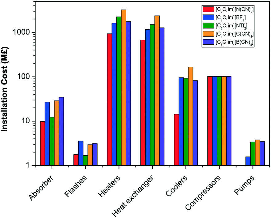 | ||
| Fig. 6 Installation cost of the main type of process units using 5 ionic liquids as solvent for CO2 capture. | ||
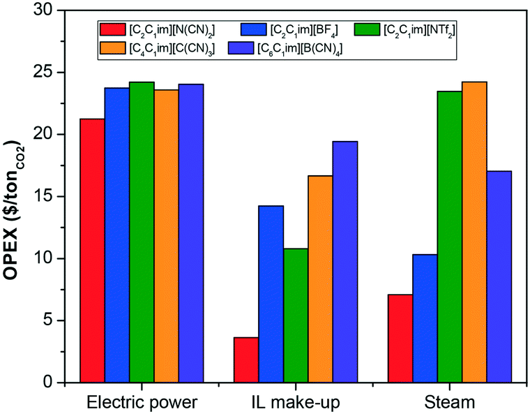
The operating costs associated with each of the selected ionic liquids are illustrated in Fig. 7. The contribution of the electricity requirements to the total operating costs of the process are practically independent on the type of ionic liquid used to capture the CO2, given that the absorption pressure was fixed, and consequently the compression duty for the flue gas. The differences in the electricity requirements are therefore due to the solvent pumping requirement, which increases proportionally to the viscosity of the ionic liquids and flow rate, i.e., inversely to CO2 uptake capacity. However, the contribution of pumping duty to the total electricity requirements of the plant is negligible relative to that require to compress the inlet exhaust gas, as illustrated in Fig. 8. Therefore, higher viscosities have a larger impact on the capital cost than on the operating cost.
 | ||
| Fig. 7 Operating costs using 5 ionic liquids as solvent for CO2 capture. | ||
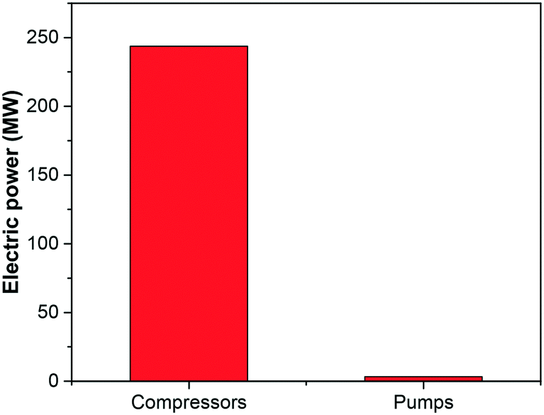 | ||
| Fig. 8 Compression and pumping electric duty of the carbon capture using the ionic liquid [C2C1im][N(CN)2]. | ||
By contrast, the cost of the heating requirements of the process, represented by the cost of steam in Fig. 7, are highly dependent on the ionic liquid. Besides the flow rate of solvent, the other properties which affect the heating requirements is the heat capacity of the ionic liquid.
The thermal energy required for the regeneration of the solvent in this plant is 410 MWth or 2.83 GJth/tCO2, which is significantly lower than the reported values for the conventional alkanolamines, i.e., 3.5–4 GJth/tCO2 depending on the configuration of the capture plant,85,86i.e., a 20–30% lower. But the quality of heat is as important as the quantity of heat. The advantage of ionic liquids with respect to amines is that the regeneration takes place at lower temperatures, i.e., at ranges between 50–70 °C, which permits the technical exploitation of waste heat from the power plant. For example, the wasted steam which leaves the low pressure turbine could potentially be utilised as heating fluid. Regeneration of amines normally require temperatures above 100 °C. This temperature is achieved by the withdrawal of steam prior to the low pressure turbine which, consequently, is not used to produce electricity.
Conversely, the total electricity required for the capture process using [C2C1im][N(CN)2] is 240 MWe or 1.65 GJth/tCO2. Considering that the full capacity of the power plant is 800 MW, the electricity requirements of the carbon capture plant imposes an energy penalty of 30%. Assuming that no steam is withdrawn for the regeneration of the ionic liquid, and that the un-abated power plant has an efficiency of 40%, the abated power plant would see its efficiency reduced to 28%. The combined thermal and electrical energy required for the solvent's regeneration is 9.1 GJth/tCO2 and significantly larger than the reported values for state of the art amines (2.33 GJth/tCO2). One can say that reducing the absorption pressure would reduce the energy demand of the capture plant. However, as discussed in the previous subsection and shown in Fig. 2, higher capital expenditure would be required in that case.
4.3 The pathway for industrial implementation of ionic liquids for CO2 capture
The most common strategy followed by researchers who aim to improve the performance of ionic liquids for CO2 capture is frequently based on improving equilibrium metrics, i.e., on increasing the capacity of the solvent to absorb CO2. This is typically achieved by functionalising the ionic liquids with CO2-philic atoms or functional groups.87,88 Fluorine (F) and cyano (CN) based anions are known for their high affinity for the CO2 molecule. Substituting the alkyl chain of cations with F or CN significantly increases the CO2 capacity, particularly at lower pressures, but at the cost of viscosity. The presence of more CO2-philic groups, which tend to be highly polar, increases the entanglement of the molecules, in addition to the dipolar inter- and intra-molecular interactions, which increases the stiffness of the molecular conformation, decreasing the freedom of movement of the ion pairs, thus increasing viscosity. As we have discussed in the previous section, larger viscosities have a significant impact on the cost; a fact that is typical neglected in assessments based on equilibrium or energy balances of the process. This effect is shown in Fig. 9 where the total annualised cost is plotted as a function of the Henry's coefficient and the viscosity. With one exception ([C2C1im][N(CN)2]), there is a trend of increasing solubility at the cost of an increased viscosity, which are caused by increased polarity. It is obvious, therefore, from these results that the cost performance of ionic liquids is not necessary ameliorated when the CO2 capacity is improved. Furthermore, other properties have not been considered when designing ionic liquid for carbon capture. Whilst heat of absorption/desorption is recurrently pointed out as a contributor to the operating cost, heat capacity is frequently neglected. However, both the capital and operating costs have been observed to be highly affected by heat capacity. Fig. 10 compares the effect of both viscosity and heat capacity on the total annual cost. Heat capacity has a similar impact on TAC than viscosity, which does not only affect the energy requirements of the plant, but also the size of the heat exchangers (see section 3.2), thus the capital cost. The ionic liquid's molar weight dominates the trends, because the heat capacity is a molar property, i.e., [C2C1im][NTf2] < [C4C4im][NTf2] < [C6C1im][NTf2].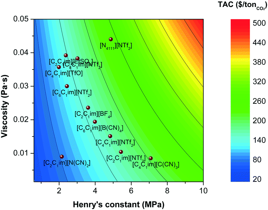 | ||
| Fig. 9 Total annualised cost (TAC) screening as a function of the Henry's coefficient and the viscosity of the ionic liquids. | ||
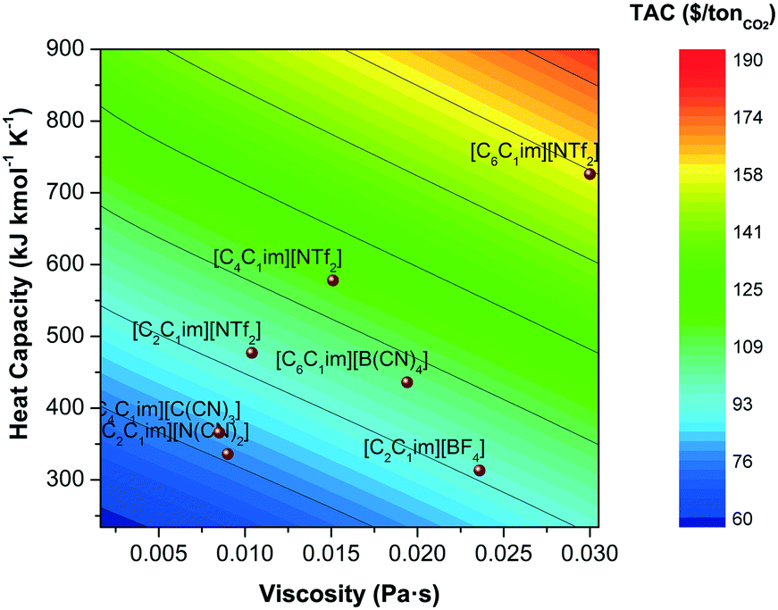 | ||
| Fig. 10 Total annualised cost (TAC) screening as a function of the heat capacity and the viscosity of the ionic liquids. | ||
The effect of changing properties on the TAC is quantitatively compared in Fig. 11 for three thermodynamic properties, i.e., viscosity, equilibrium constant and heat capacity. A relative change in TAC smaller than one results in decreased capture costs with regards to a process using the benchmark ionic liquid, [C4C1im][NTf2]. A relative property change smaller than one, represents an ionic liquid with a lower property, i.e., viscosity, than [C4C1im][NTf2]. Changing the equilibrium constant, with otherwise unaltered properties, shows the most prominent effect on TAC and could halve the capture costs with a relative reduction to 40% of the benchmark's equilibrium constant. However, the dominating and outweighing effect of the large viscosities can only be seen in the context of the absolute results shown in Fig. 9 and 10.
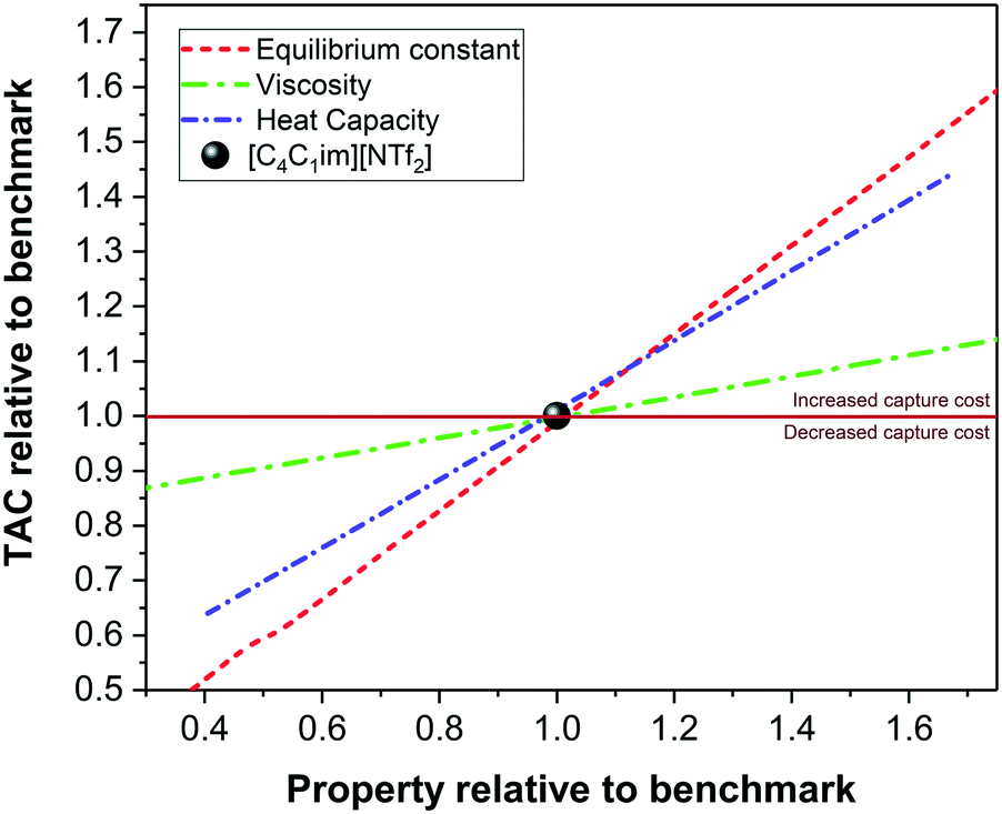 | ||
| Fig. 11 Relative effect on the total annualised cost (TAC) as a function of the relative viscosity, heat capacity and equilibrium constant with respect to a capture plant using the benchmark solvent [C4C1im][NTf2]. | ||
5 Conclusions
We have presented an assessment of ionic liquid as potential solvents for CO2 capture from flue gas based on key process performance indicators (KPI's). Monetised (e.g., CAPEX, OPEX and TAC) and non-monetised (e.g., absorber height) KPI's are evaluated as a function of the thermodynamic and transport characteristics of the ionic liquid, namely, gas capacity (expressed in terms of Henry's coefficients), viscosity, density, heat capacity, thermal conductivity and surface tension of the solvent.Despite the fact that there are tens of thousand of IL-CCS studies,89 and that more than 100 ionic liquids have been presented as promising solvents for CO2 capture, less than 30 ionic liquids have all these properties evaluated in the temperature and composition range of interest for this particular process. This prevents the actual assessment of their potential from a process performance perspective, and also creates uncertain or inaccurate property targets for solvent design.
We presented the cost performance of selected ionic liquids as solvents for a carbon capture plant from an archetypal 800 MW supercritical pulverised coal power plant. Our results have shown that CO2 capacity of ionic liquids is not the only characteristic that influences their process performance. The contribution of other properties, such as viscosities and heat capacity, to the total cost of the process, i.e., both the capital and operating cost, is frequently ignored. However, we have demonstrated that these properties have a decisive influence on the feasibility of the process. In order of relative prominence (as shown in Fig. 11), the properties which have a direct impact on the TAC are:
1. Solubility of CO2
2. Heat capacity
3. Viscosity
4. Heat of absorption
5. Density
6. Surface tension
Our results demonstrate that many ionic liquids which have been described as highly CO2-philic and moderately viscous, e.g., [C6C1im][B(CN)4],62 do not present favourable economic metrics. Therefore, claiming that an ionic liquid is a promising solvent for carbon capture must not be based solely on the description of the CO2 capacity, but on a systemic assessment of their various thermophysical properties coupled to a monetised description of their process performance.
Many studies postulate that ionic liquids have a lower energy penalty than conventional solvents. This claim is true when the regeneration enthalpy is the only contribution considered, since the heat of regeneration of ionic liquids is considerably lower (∼2.8 GJth/tCO2) than that of conventional amines (3.5–4 GJth/tCO2).85,86 However, a more detailed study on the total energy requirements shows that, in fact, the electricity, particularly that associated principally to the flue gas compression, imposes a high energy penalty which reduces the efficiency of the power plant from 40% (un-abated) to 28% (abated). Whilst reducing the absorption pressure would reduce the electricity demand of the capture plant, this work indicates that doing so would result in a significant increase in CAPEX.
With this in mind, it is clear that a new approach must be made when designing ionic liquids for carbon capture, or indeed for any application. The various physical properties of the solvent have an immense effect on process performance, suggesting that solvent design targets should be set with other key process performance targets in mind; specifically, the trade-off between CO2 capacity and solvent physical properties (e.g. viscosity in particular) must be considered on an equally weighted basis. For example, ionic liquids design for CO2 capture should consider low viscosity as a primary design criterion. This would necessitate the incorporation of lower viscosity functional groups and ions, with the cost increase kept in check as the solvent complexity increases. Higher viscosity should only be accepted if the commensurate increase in CO2 capacity warrants it. Reducing the interactions between the cation and anion is the most straightforward means of lowering the ionic liquid's viscosity. Depending on whether the cation or anion has been designed to enhance CO2 capacity (both approaches exist in the literature) it would be prudent to assess the impact of utilizing a less interacting counterion in order to reduce ionic interactions and therefore viscosity. While this does add an extra dimension for optimization, it also discounts the impact of using both ions to interact strongly with CO2. These multi-functional solvents are likely to be too strongly associating to have low viscosity. In general, the functionalization of ionic liquid ions (especially cations) needs to carefully consider the process implications alongside the increase in CO2 capacity. A large spike in viscosity is unlikely to be worth a modest increase in solubility. Less interacting cations (e.g., those with longer alkyl chains) will offer some advantages through viscosity reduction, and these appear to counteract any mild decrease in capacity. Less interacting anions are likely to be more complicated, but it appears that three-dimensionally asymmetric ions (such as the linear dicyanamide anion [N(CN)2]) will reduce the ionic liquid's viscosity without compromising capacity. Pairing an anion such as this with a functionalized cation would provide an excellent first approach for solvent design, provided the ionic liquid's viscosity is monitored throughout the design process.
The application of ionic liquids as solvents for carbon capture in large scale will only be possible if their economic assessment is more favourable than existing solvents which have been already used at large scale. We found that the annual cost of the plant using ionic liquids is of the same order of magnitude than 30% MEA. Nevertheless, ionic liquids are highly tunable, and using the right design tools new chemical structures with improved process performance could be designed. However, this will only be possible with an approach which bridges the gap between the properties of the ionic liquid and the cost of the process.
Conflicts of interest
The authors declare that there are no conflicts to declare.Acknowledgements
The UK Carbon Capture and Storage Research Centre (UKCCSRC) is supported by the Engineering and Physical Sciences Research Council (EPSRC) as part of the Research Councils UK Energy Programme, with additional funding from the Department of Business, Energy and Industrial Strategy (BEIS - formerly DECC).References
- S. Gabriel and J. Weiner, Ber. Dtsch. Chem. Ges., 1888, 21, 2669–2679 CrossRef.
- P. Walden, Izv. Imp. Akad. Nauk, 1914, 8, 405–422 Search PubMed.
- K. R. Seddon, J. Chem. Technol. Biotechnol., 1997, 68, 351–356 CrossRef CAS.
- M. Freemantle, Chem. Eng. News, 1998, 76, 32–37 Search PubMed.
- M. Freemantle, Chem. Eng. News, 2000, 78, 37–50 Search PubMed.
- J. G. Huddleston and R. Rogers, Chem. Commun., 1998, 1765–1766 RSC.
- F. van Rantwijk and R. A. Sheldon, Chem. Rev., 2007, 107, 2757–2785 CrossRef CAS PubMed.
- A. A. C. Toledo Hijo, G. J. Maximo, M. C. Costa, E. A. C. Batista and A. J. A. Meirelles, ACS Sustainable Chem. Eng., 2016, 4, 5347–5369 CrossRef CAS.
- S. H. Ha, R. N. Menchavez and Y.-M. Koo, Korean J. Chem. Eng., 2010, 27, 1360–1365 CrossRef CAS.
- S. J. Devaki and R. Sasi, Progress and Developments in Ionic Liquids, InTech, 2017, ch. Ionic Liquids/Ionic Liquid Crystals for Safe and Sustainable Energy Storage Systems, https://www.intechopen.com/books/progress-and-developments-in-ionic-liquids/ionic-liquids-ionic-liquid-crystals-for-safe-and-sustainable-energy-storage-systems Search PubMed.
- M. Watanabe, M. L. Thomas, S. Zhang, K. Ueno, T. Yasuda and K. Dokko, Chem. Rev., 2017, 117, 7190–7239 CrossRef CAS PubMed.
- M. Alvarez-Guerra, J. Albo, E. Alvarez-Guerra and A. Irabien, Energy Environ. Sci., 2015, 8, 2574–2599 CAS.
- L. D. Simoni, J. F. Brennecke and M. A. Stadtherr, Ind. Eng. Chem. Res., 2009, 48, 7246–7256 CrossRef CAS.
- N. R. Rodriguez, A. S. B. Gonzalez, P. M. A. Tijssen and M. C. Kroon, Fluid Phase Equilib., 2015, 385, 72–78 CrossRef CAS.
- S. P. da Silva, A. M. da Costa Lopes, L. B. Roseiro and R. Bogel-Lukasik, RSC Adv., 2013, 3, 16040–16050 RSC.
- A. Brandt, J. Grasvik, J. P. Hallett and T. Welton, Green Chem., 2013, 15, 550–583 RSC.
- A. E. Visser, R. P. Swatloski, W. M. Reichert, S. T. Griffin and R. D. Rogers, Ind. Eng. Chem. Res., 2000, 39, 3596–3604 CrossRef CAS.
- D. Parmentier, S. J. Metz and M. C. Kroon, Green Chem., 2013, 15, 205–209 RSC.
- T. Vander Hoogerstraete, S. Wellens, K. Verachtert and K. Binnemans, Green Chem., 2013, 15, 919–927 RSC.
- R. E. Baltus, R. M. Counce, B. H. Culbertson, H. Luo, D. W. DePaoli, S. Dai and D. C. Duckworth, Sep. Sci. Technol., 2005, 40, 525–541 CrossRef CAS.
- M. Ramdin, T. W. de Loos and T. J. Vlugt, Ind. Eng. Chem. Res., 2012, 51, 8149–8177 CrossRef CAS.
- M. Maase and K. Massonne, in Biphasic Acid Scavenging Utilizing Ionic Liquids: The First Commercial Process with Ionic Liquids, 2015, ch. 10, pp. 126–132 Search PubMed.
- J. D. Holbrey, N. V. Plechkova and K. R. Seddon, Green Chem., 2006, 8, 411–414 RSC.
- L. Chen, M. Sharifzadeh, N. Mac Dowell, T. Welton, N. Shah and J. P. Hallett, Green Chem., 2014, 16, 3098–3106 RSC.
- N. V. Plechkova and K. R. Seddon, Chem. Soc. Rev., 2008, 37, 123–150 RSC.
- R. S. Eisinger and G. E. Keller, Energy Fuels, 2014, 28, 7070–7078 CrossRef CAS.
- H. Zhai and E. S. Rubin, Energy Procedia, 2014, 63, 1321–1328 CrossRef CAS.
- M. B. Shiflett, D. W. Drew, R. A. Cantini and A. Yokozeki, Energy Fuels, 2010, 24, 5781–5789 CrossRef CAS.
- K. Khonkaen, K. Siemanond and A. Henni, 24th European Symposium on Computer Aided Process Engineering, Elsevier, 2014, vol. 33, pp. 1045–1050 Search PubMed.
- T. Ma, J. Wang, Z. Du, A. A. Abdeltawab, A. M. Al-Enizi, X. Chen and G. Yu, Int. J. Greenhouse Gas Control, 2017, 58, 223–231 CrossRef CAS.
- J. de Riva, J. Suarez-Reyes, D. Moreno, I. Diaz, V. Ferro and J. Palomar, Int. J. Greenhouse Gas Control, 2017, 61, 61–70 CrossRef CAS.
- A. Jongpitisub, K. Siemanond and A. Henni, Chem. Eng. Trans., 2015, 43, 1495–1500 Search PubMed.
- Y. Xie, Y. Zhang, X. Lu and X. Ji, Appl. Energy, 2014, 136, 325–335 CrossRef CAS.
- M. J. Earle, J. M. S. S. Esperanca, M. A. Gilea, J. N. Canongia Lopes, L. P. N. Rebelo, J. W. Magee, K. R. Seddon and J. A. Widegren, Nature, 2006, 439, 831–834 CrossRef CAS PubMed.
- M. A. A. Rocha, C. F. R. A. C. Lima, L. R. Gomes, B. Schröder, J. A. P. Coutinho, I. M. Marrucho, J. M. S. S. Esperança, L. P. N. Rebelo, K. Shimizu, J. N. C. Lopes and L. M. N. B. F. Santos, J. Phys. Chem. B, 2011, 115, 10919–10926 CrossRef CAS PubMed.
- L. I. Helgesen and E. Gjernes, Energy Procedia, 2016, 86, 239–251 CrossRef CAS.
- R. D. Rogers and K. R. Seddon, Science, 2003, 302, 792–793 CrossRef PubMed.
- L. A. Blanchard, D. Hancu, E. J. Beckman and J. F. Brennecke, Nature, 1999, 399, 28–29 CrossRef.
- L. A. Blanchard, Z. Gu and J. F. Brennecke, J. Phys. Chem. B, 2001, 105, 2437–2444 CrossRef CAS.
- J. L. Anthony, E. J. Maginn and J. F. Brennecke, J. Phys. Chem. B, 2002, 106, 7315–7320 CrossRef CAS.
- A. P. S. Kamps, D. Tuma, J. Z. Xia and G. Maurer, J. Chem. Eng. Data, 2003, 48, 746–749 CrossRef.
- Z. Liu, W. Wu, B. Han, Z. Dong, G. Zhao, J. Wang, T. Jiang and G. Yang, Chem. – Eur. J., 2003, 9, 3897–3903 CrossRef CAS PubMed.
- A. Shariati and C. J. Peters, J. Supercrit. Fluids, 2004, 29, 43–48 CrossRef CAS.
- A. Shariati and C. J. Peters, J. Supercrit. Fluids, 2004, 30, 139–144 CrossRef CAS.
- S. N. V. K. Aki, B. R. Mellein, E. M. Saurer and J. F. Brennecke, J. Phys. Chem. B, 2004, 108, 20355–20365 CrossRef CAS.
- D. Camper, P. Scovazzo, C. Koval and R. Noble, Ind. Eng. Chem. Res., 2004, 43, 3049–3054 CrossRef CAS.
- A. Shariati, K. Gutkowski and C. J. Peters, AIChE J., 2005, 51, 1532–1540 CrossRef CAS.
- M. B. Shiflett and A. Yokozeki, Ind. Eng. Chem. Res., 2005, 44, 4453–4464 CrossRef CAS.
- Y. S. Kim, W. Y. Choi, J. H. Jang, K. P. Yoo and C. S. Lee, Fluid Phase Equilib., 2005, 228–229, 439–445 CrossRef CAS.
- J. Jacquemin, P. Husson, V. Majer and M. F. C. Gomes, Fluid Phase Equilib., 2006, 240, 87–95 CrossRef CAS.
- M. Costantini, V. A. Toussaint, A. Shariati, C. J. Peters and I. Kikic, J. Chem. Eng. Data, 2005, 50, 52–55 CrossRef CAS.
- K. I. Gutkowski, A. Shariati and C. J. Peters, J. Supercrit. Fluids, 2006, 39, 187–191 CrossRef CAS.
- R. E. Baltus, B. H. Culbertson, S. Dai, H. Luo and D. W. DePaoli, J. Phys. Chem. B, 2003, 108, 721–727 CrossRef.
- A. M. Schilderman, S. Raeissi and C. J. Peters, Fluid Phase Equilib., 2007, 260, 19–22 CrossRef CAS.
- J. L. Anderson, J. K. Dixon and J. F. Brennecke, Acc. Chem. Res., 2007, 40, 1208–1216 CrossRef CAS PubMed.
- W. Ren, B. Sensenich and A. M. Scurto, J. Chem. Thermodyn., 2010, 42, 305–311 CrossRef CAS.
- A. N. Soriano, B. T. D. Jr and M.-H. Li, J. Chem. Thermodyn., 2009, 41, 525–529 CrossRef CAS.
- R. Babarao, S. Dai and D. Jiang, J. Phys. Chem. B, 2011, 115, 9789–9794 CrossRef CAS PubMed.
- J. A. P. Coutinho, P. J. Carvalho and K. A. Kurnia, Phys. Chem. Chem. Phys., 2016, 18, 14757–14771 RSC.
- D. R. MacFarlane, J. Golding, S. Forsyth, M. Forsyth and G. B. Deacon, Chem. Commun., 2001, 1430–1431 RSC.
- C. M. S. S. Neves, K. A. Kurnia, J. A. P. Coutinho, I. M. Marrucho, J. N. C. Lopes, M. G. Freire and L. P. N. Rebelo, J. Phys. Chem. B, 2013, 117, 10271–10283 CrossRef CAS PubMed.
- M. T. Mota-Martinez, M. Althuluth, M. C. Kroon and C. J. Peters, Fluid Phase Equilib., 2012, 332, 35–39 CrossRef CAS.
- G. E. Romanos, L. F. Zubeir, V. Likodimos, P. Falaras, M. C. Kroon, B. Iliev, G. Adamova and T. J. S. Schubert, J. Phys. Chem. B, 2013, 117, 12234–12251 CrossRef CAS PubMed.
- L. F. Zubeir, G. E. Romanos, W. M. A. A. Weggemans, B. Iliev, J. S. Thomas, T. J. S. Schubert and M. C. Kroon, J. Chem. Eng. Data, 2015, 60, 1544–1562 CrossRef CAS.
- M. T. Mota-Martinez, J. P. Hallett and N. Mac Dowell, Sustainable Energy Fuels, 2017, 1, 2078–2090 CAS.
- C. Kolster, E. Mechleri, S. Krevor and N. Mac Dowell, Int. J. Greenhouse Gas Control, 2017, 58, 127–141 CrossRef CAS.
- W. K. Lewis and W. G. Whitman, Ind. Eng. Chem., 1924, 16, 1215–1220 CrossRef CAS.
- K. Onda, H. Takeuchi and Y. Okumoto, J. Chem. Eng. Jpn., 1968, 1, 56–62 CrossRef CAS.
- C. R. Wilke and P. Chang, AIChE J., 1955, 1, 264–270 CrossRef CAS.
- C. Moya, J. Palomar, M. Gonzalez-Miquel, J. Bedia and F. Rodriguez, Ind. Eng. Chem. Res., 2014, 53, 13782–13789 CrossRef CAS.
- D. Q. Kern, Process Heat Transfer, McGraw-Hill, New York, 1950, p. 871 Search PubMed.
- R. K. Sinnott, Coulson and Richardson's Chemical Engineering, Oxford, Butterworth-Heinemann, 4th edn, 2005, ch. Heat-Trans Search PubMed.
- D. W. Green and R. H. Perry, Perry's Chemical Engineers' Handbook, McGraw-Hill, New York, Chicago, San Francisco, Lisbon, London, Madrid, Mexico City, Milan, New Delhi, San Juan, Seoul, Singapore, Sydney, Toronto, New York, 2008 Search PubMed.
- J. R. Couper, Chemical Process Equipment Selection and Design, Butterworth-Heinemann, 2nd edn, 1990, ch. 21 Cost, pp. 663–690 Search PubMed.
- A. Annut, Prices of fuels purchased by major power producers, 2016, http://bit.ly/2tPywjI Search PubMed.
- N. Mac Dowell and N. Shah, Comput. Chem. Eng., 2015, 74, 169–183 CrossRef CAS.
- O. Aschenbrenner, S. Supasitmongkol, M. Taylor and P. Styring, Green Chem., 2009, 11, 1217–1221 RSC.
- D. O'Brien, D. Stewart, J. W. Harris, M. A. Schultz, M. S. M. Shakur and S. P. Rosenblum, The Chemical Engineer, 2002, 64–71 Search PubMed.
- PETRONAS Refinery and Petrochemical Corporation Sdn Bhd (PRPC), Tallest and heaviest fractionator process column arrives in Pengerang, 2016, http://bit.ly/2u0P6C8 Search PubMed.
- {http://www.worldatlas.com/articles/10-tallest-buildings-in-the-world.html}.
- L. F. Zubeir, M. A. A. Rocha, N. Vergadou, W. M. A. Weggemans, L. D. Peristeras, P. S. Schulz, I. G. Economou and M. C. Kroon, Phys. Chem. Chem. Phys., 2016, 18, 23121–23138 RSC.
- E. Crooks, World's biggest carbon capture project on schedule, 2017, https://www.ft.com/content/eee0d5d6-d700-11e6-944b-e7eb37a6aa8e?mhq5j=e3 Search PubMed.
- L. Raynal, P.-A. Bouillon, A. Gomez and P. Broutin, Chem. Eng. J., 2011, 171, 742–752 CrossRef CAS.
- P. Brandl, S. M. Soltani, P. S. Fennell and N. M. Dowell, Chem. Eng. Res. Des., 2017, 122, 1–10 CrossRef CAS.
- I. Kim, K. A. Hoff, E. T. Hessen, T. Haug-Warberg and H. F. Svendsen, Chem. Eng. Sci., 2009, 64, 2027–2038 CrossRef CAS.
- J. Oexmann and A. Kather, Int. J. Greenhouse Gas Control, 2010, 4, 36–43 CrossRef CAS.
- J. F. Brennecke and B. E. Gurkan, J. Phys. Chem. Lett., 2010, 1, 3459–3464 CrossRef CAS.
- M. E. Boot-Handford, J. C. Abanades, E. J. Anthony, M. J. Blunt, S. Brandani, N. Mac Dowell, J. R. Fernández, M.-C. Ferrari, R. Gross, J. P. Hallett, R. S. Haszeldine, P. Heptonstall, A. Lyngfelt, Z. Makuch, E. Mangano, R. T. J. Porter, M. Pourkashanian, G. T. Rochelle, N. Shah, J. G. Yao and P. S. Fennell, Energy Environ. Sci., 2014, 7, 130–189 CAS.
- A. Samanta, A. Zhao, G. K. H. Shimizu, P. Sarkar and R. Gupta, Ind. Eng. Chem. Res., 2012, 51, 1438–1463 CrossRef CAS.
Footnotes |
| † Other descriptions of mass transfer coefficients, e.g., Billet and Schultes, etc., could equally well be used. |
| ‡ The tallest process columns in the world are below 150 m. e.g., Linde constructed a dividing-wall distillation column (DWC) of an estimated height of 107 m,78 and Petronas installed a 121.3 m fractionator column in Malaysia.79 |
| § At the time of writing, the tallest building in the world is the Burj Khalifa in Dubai, United Arab Emirates, which is 828 m tall.80 The tallest building in Malaysia is the Petronas twin towers which are 451.9 m tall;80 3.75 times higher than their tallest process column. |
| ¶ The cost of the carbon capture using 30% MEA from the same archetypal power plant was estimated using a similar methodological approach.65 The cost assessment does not include the compression and dehydration cost, which is estimated in the order of $20–25/tCO2.66 Cost of carbon capture plants at industrial scale such as the Petra Nova Carbon Capture Project is currently estimated to be $70/tCO2.82 |
| This journal is © The Royal Society of Chemistry 2018 |