
Tuning chain interaction entropy in complex coacervation using polymer stiffness, architecture, and salt valency
Tyler K.
Lytle
a and
Charles E.
Sing
 *b
*b
aDepartment of Chemistry, University of Illinois at Urbana-Champaign, Urbana, IL, USA
bDepartment of Chemical and Biomolecular Engineering, University of Illinois at Urbana-Champaign, 600 S. Mathews Ave., Urbana, IL, USA. E-mail: cesing@illinois.edu; Tel: 217 244 6671
First published on 6th November 2017
Abstract
Oppositely-charged polyelectrolytes can undergo a liquid–liquid phase separation in a salt solution, resulting in a polymer-dense ‘coacervate’ phase that has found use in a wide range of applications from food science to self-assembled materials. Coacervates can be tuned for specific applications by varying parameters such as salt concentration and valency, polyelectrolyte length, and polyelectrolyte identity. Recent simulation and theory has begun to clarify the role of molecular structure on coacervation phase behavior, especially for common synthetic polyelectrolytes that exhibit high charge densities. In this manuscript, we use a combination of transfer matrix theory and Monte Carlo simulation to understand at a physical level how a range of molecular features, in particular polymer architecture and stiffness, and salt valency can be used to design the phase diagrams of these materials. We demonstrate a physical picture of how the underlying entropy-driven process of complex coacervation is affected by this wide range of physical attributes.
Design, System, ApplicationThis paper outlines a molecular-based design strategy for tuning interactions in charged, soft matter systems. Using the specific example of polycation/polyanion interactions, we expect the underlying principles we outline to apply in a range of charge-driven associations; namely, association thermodynamics can be systematically tuned by altering the configurational entropy of interaction using a number of molecular features. In polymers, we specifically focus on stiffness, valency, architecture, however we envision this strategy being broadly applicable to other types of molecular features soft materials. This is immediately relevant to a applications in charge-driven self-assembly, where it is important to tune soft material interactions to attain desired structures and properties. Our theoretical and computational insight will enable experimentalists to dial in desired material interactions in an informed fashion. |
1 Introduction
Oppositely-charged polyelectrolytes in salt solutions can undergo a process known as complex coacervation, which is an associative phase separation resulting in two phases: a polyelectrolyte-dense coacervate phase and a polyelectrolyte-dilute supernatant phase.1–3 Coacervates are widely used in the food industry as encapsulants or viscosity modifiers,4–6 and recent research has begun to explore their potential in underwater adhesives7–9 or self-assembled structures for drug delivery.10–12 The utility of coacervation in this wide array of applications stems from the ability to tune or manipulate phase behavior using electrostatics, in particular using salt concentration to affect miscibility.3,13The experimental literature on coacervation has demonstrated that coacervate phase behavior is sensitive to the molecular chemistry of the polyelectrolyte and salt components.14–23 Polymer chemistry in particular plays a significant role, with coacervation aided by short-range attractions such as hydrophobicity.18 Chemical structural features can also lead to the formation of solid ‘precipitates’ that are sensitive to hydrogen-bonding and chirality, and are distinguished from coacervate droplets by their irregular shape and expulsion of most water.15,19,24 Despite these strong effects on coacervation, it remains difficult to precisely design polymer chemistry for a desired phase behavior.
Physical molecular features of both the salt and the polymer also play a significant role in coacervation, and in contrast to polymer chemistry represent a convenient way to manipulate coacervate phase behavior in a controlled fashion. For example, coacervation is sensitive to salt valency, with phase separation suppressed in the presence of multivalent salts.9,18,23 Polymer length also has a pronounced effect on coacervation,21 with longer polymers possessing less translational entropy per charge and thus forming more stable coacervates. Other examples considered in the experimental literature include comb polyelectrolytes25 and patterned polyelectrolytes.26 For the former, the coacervation phase boundary shrinks when linear chains are replaced with short charged branches.25 For the latter, blocky charge sequences are shown to exhibit a larger region of coacervation than alternating charge sequences on a coacervate-forming polyelectrolyte.26
A physical understanding of how these molecular-level features affect the complex coacervation phase diagram can inform the design parameters utilized for material applications. Theoretical efforts to make this connection are challenging due to the difficulty of correctly describing the electrostatic interactions between the charged species involved in coacervation (polycation, polyanion, cation, and anion).13,27 The classical Voorn–Overbeek theory was the first effort at predicting coacervation, using a free energy function that combined a Flory–Huggins mixing entropy for all of the molecular species and a Debye–Hückel interaction energy for the electrostatics.2,28–30 This theory captured the key phenomenological aspects of coacervation; electrostatic attractions between the charged species favor coacervate formation, but mixing entropy begins to dominate at high polymer and salt concentrations where charges are strongly screened. Voorn–Overbeek theory can be used to describe experimental measurements of phase separation,21 but the fit parameters related to electrostatic interaction strength and charge density have been found to be unphysical.20,31 The inaccuracy of Voorn–Overbeek theory stems from the use of Debye–Hückel to describe electrostatic interactions. Debye–Hückel makes no distinction between salt ion charges and polymer charges, therefore neglecting the connected nature of the polyelectrolyte charges.31
This deficiency of Voorn–Overbeek theory is well known, and there has been significant effort to address this particular shortcoming. One route has been to improve on this theory via increasingly sophisticated field theory methods, typically building off a random phase approximation (RPA) approach.32–38 RPA models are capable of demonstrating the importance of the connections between polymeric charges; however, they become increasingly inaccurate for high charge-density polymers.33 Modifications can be made to standard RPA to account for this limitation,37 however these modifications are typically ad hoc and do not fully capture the local polyelectrolyte and charge correlations that are needed to describe high charge-density coacervates.31,39 Full field theoretic simulations are in principle capable of moving past these inadequacies,40–42 but so far have not been used to probe the effects of molecular structure.
These limitations of field-based methods have become increasingly apparent. In particular, coarse-grained computational efforts have been able to demonstrate the profound importance of molecular structure in particle models.19,20,24 Furthermore, calorimetry demonstrates that coacervation is primarily entropically driven, demonstrating the need to reevaluate the role of electrostatics in coacervation.17,26,43 This has inspired a number of alternative theoretical approaches.23,43,44 The theoretical concept of counterion condensation and release, which is typically used to describe complexes of two oppositely-charged chains,45–47 has been particularly useful. Prior to complexation, counterions are condensed on both polyelectrolytes to decrease linear charge density.48 When these chains interact, they decrease each other's linear charge density, and release the condensed counterions.46 Therefore, coacervation is driven by a gain in counterion translational entropy, consistent with calorimetry. Recent efforts have focused on incorporating this entropy-based picture into coacervate theory.44,49 The authors have recently developed a transfer-matrix model inspired by this picture, which maps coacervation to a one-dimensional adsorption theory.49 The resulting analytical model captures coacervate molecular structure and thermodynamics observed in simulation,49 importantly in the high charge-density limit that is not captured by RPA-based approaches.32–38 This model provides the foundations for further study of molecular features in complex coacervation.
This manuscript uses a combination of transfer matrix theory and coarse-grained simulation to understand the role of polymer physical parameters on complex coacervation; namely, we study the role of salt valency, polymer architecture, and polymer stiffness. This builds upon the original transfer matrix theory for coacervation, which was tested by varying model parameters, and now extends its application to molecular attributes that are widely known to be important for polyelectrolyte systems. For example, chain flexibility is known to affect DNA packing into virus capsids,50–52 and affects its complexation with polyanions in drug delivery vehicles known as ‘polyplexes’.53–58 Similarly, dendrimers59 and brushes60 are polymer architectures that exhibit rich polyelectrolyte physics beyond linear chains, and there is experimental and simulation evidence that branches play an important role in coacervation25 and complexation.53,54 Finally, valency is known to strongly affect polyelectrolyte properties in a wide variety of systems, ranging from single chains61 to brushes,62,63 gels,64,65 and solutions.66,67
We will demonstrate that all these features – architecture, stiffness, and counterion valency – indeed affect complex coacervation, driving significant changes in phase behavior. We demonstrate that the phase behavior of comb polymers are affected by a combination of excluded volume and counterion condensation considerations, and qualitatively matching simulation and a modified version of our transfer-matrix coacervation model. We also show how increasing polymer stiffness suppresses coacervation, due to the entropic penalty of aligning neighboring polyelectrolyte chains. Finally, we extend our theory to account for multivalent effects, by accounting for the combinatoric entropy of counterion pairing. This overall model provides the physical basis for understanding how complex coacervate phase behavior can be tuned on a molecular level.
2 Coarse-grained simulation of coacervate phase behavior
Complex coacervation is studied using a coarse-grained Monte Carlo (MC) simulation.20,68 The charged species interact via Coulomb interactions in the presence of an implicit solvent, where both polyelectrolytes and counterions are explicitly represented. We use a method developed by our group that uses this molecular-level simulation to parameterize a field theory,49,69 enabling us to directly calculate a phase diagram. Specifically, Widom insertion is used to calculate the excess chemical potential, μEXC, of the salt and polymer species at a number of polymer and salt volume fractions, ϕP and ϕS. μEXC is thermodynamically integrated to yield the excess free energy fEXC (ϕP, ϕS) that is a function of ϕP and ϕS.69 This function can be incorporated into standard polymer field theory, and can be used to predict phase diagrams.69 We note that this method is discussed in detail in prior work,69 which includes direct comparison with experiment and validation with standard methods for calculating phase diagrams using molecular simulation, such as Gibbs ensemble.20,692.1 Restricted primitive model of coacervation
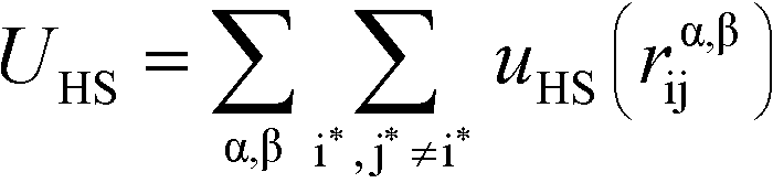
Our simulation model considers nP+ polycation chains, nP− polyanion chains, n+ cations, and n− anions. Positions of beads i and species α are denoted as rαi, where the species α = P+, P−, +, − for polycation, polyanion, cation, and anion respectively. Water is included as an implicit solvent with a dielectric constant, εr = 78.5. All charged beads are represented as hard spheres (salt ions) or connected hard spheres (polymers) with a diameter σ. We note that this restricted primitive model (RPM)70 representation neglects atomistic-level effects thought to play a role in coacervation, such as specific ion effects or water structure, however previous work has demonstrated that this model captures qualitative trends.20,25,26N P+ and NP− are the number of charged polycation and polyanion beads, respectively. We consider two types of architectures in this investigation; linear and comb polymers. Linear polymers are modeled with NP+ and NP− beads that are all charged, with no additional monomers, such that NP+ = NP− = N. Comb polymers have N0 uncharged backbone monomers in addition to the NP+ or NP− charged beads, so that a comb polycation (for example) has N = N0 + NP+ total beads. The degree of polymerization of the branch is given by Nb, so the number of branches is given by NP+/Nb and the number of uncharged backbone monomers between branches is Ns = N0Nb/NP+. We show schematics of both the linear and comb polymers in Fig. 1.
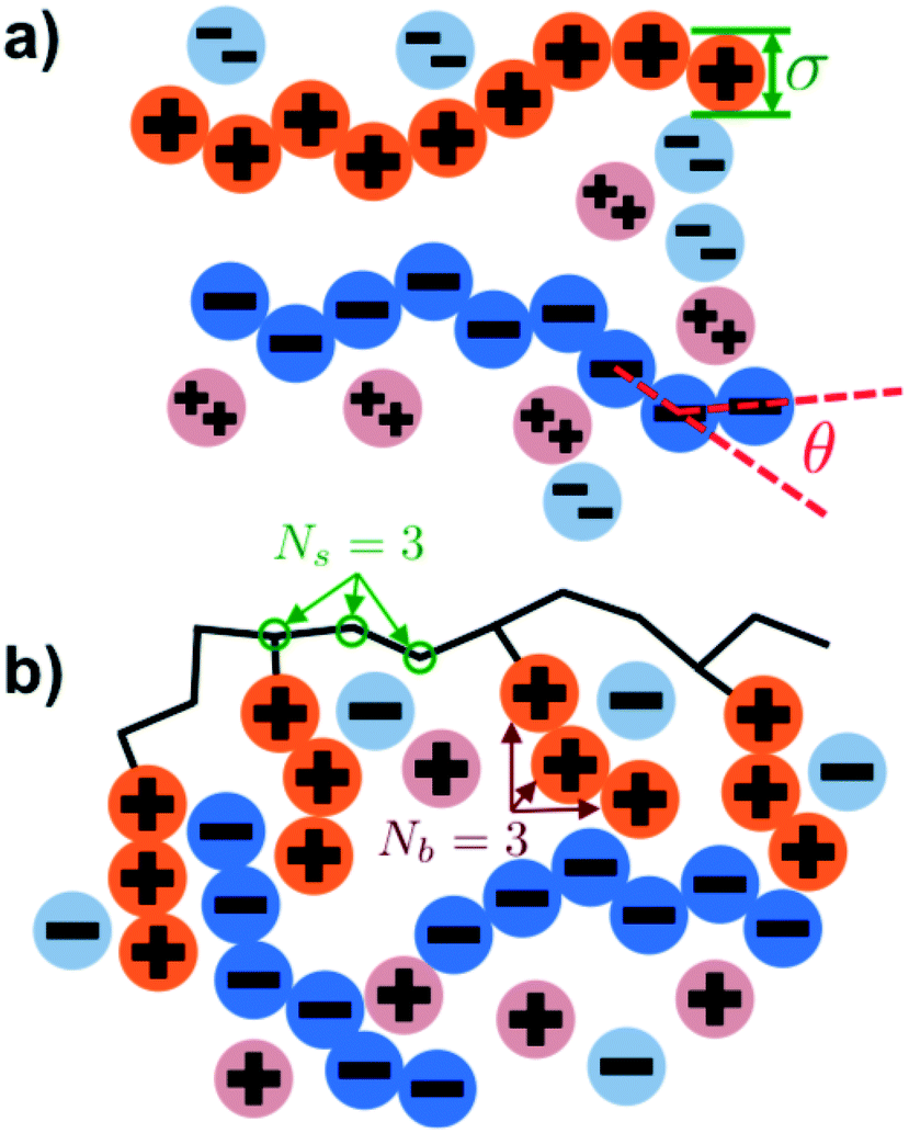 | ||
| Fig. 1 Schematics illustrating the coacervate models used in our Monte Carlo simulation. (a) Linear polyelectrolytes are modeled as a series of charged beads connected together at a distance of σ, which is also the bead diameter. Chain stiffness is included via an energetic penalty for bending angles θ. Salt valency can be changed, with divalent salts shown in this figure. (b) Comb polymers are modeled with branches of Nb charges each, positioned every Ns backbone monomers. In this work, we focus on coacervates formed from comb polycations and linear polyanions. | ||
2.2 Monte Carlo coacervate simulations
We perform MC simulations on this RPM-based polyelectrolyte model, with MC updates that consider the total system energy U given by:| U = UHS + UE + UB + Uθ | (1) |
U HS is a hard sphere potential preventing overlap of charged beads:
 | (2) |
Here, the asterisks specify that the summation does not include uncharged beads (i.e. the backbone of comb polymers) that are not modeled with excluded volume. This choice was made to reflect the lack of the strong hydration shell around neutral monomers, in comparison with charged species. In this equation rα,βij = ∣rαi − rβj∣ denoting the distance between beads i and j of species α and β. uHS is the pair potential:
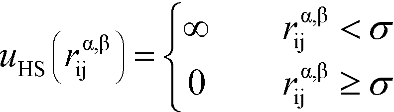 | (3) |
U E is the electrostatic potential:
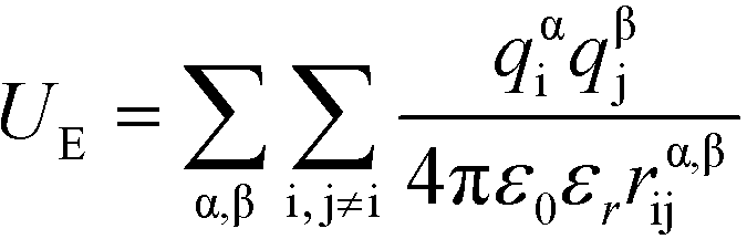 | (4) |
 | (5) |
α is limited to being along connected polymer chains, the dagger indicates that the sum is only over bonded monomers i and j, and uB is the pair potential:
 | (6) |
The flexibility of the polymers is controlled by Uθ given by
 | (7) |
α is limited to being along connected polymer chains, the double dagger denotes the sum is over monomers i, j, and k connected by two bonds. The angle pair potential is uθ:
 | (8) |
For linear polymers, we use the parameters σ = 0.425 nm, N = 100, and nP+ = nP− = 4. For comb polymers we use σ = 0.425 nm, NP+ = 120, NS = 3, nP+ = 3, and nP− = 3. We describe the parameters for stiffness (κθ) and branch length Nb in their respective results sections. Salt is monovalent zαi = 1 except where noted. Simulations were run for at least 1 × 10⁷ cycles, and translational MC moves were utilized.72 Simulations were performed with a variety of box sizes to check that there were no finite box size effects, and multiple starting configurations were tested to check that simulations with divalent ions were equilibrated.
2.3 Molecular simulation-informed polymer field theory
Excess chemical potentials μEXC,S and μEXC,P were calculated using standard Widom insertion,68,69 along with the chain-growth method of calculating μEXC,P.73 Electroneutrality is maintained during Widom insertion by inserting cation/anion pairs or polycation/polyanion monomer pairs. For comb polyelectrolytes, the chain-growth method was performed as in previous work by the authors to reflect the comb architecture.25 Chemical potentials for each species were tabulated at a number of values of ϕS and ϕP, and were thermodynamically integrated to yield the excess free energy fEXC (ϕS,ϕP): | (9) |
Here, ϕ0S and ϕ0P serve as reference states. We incorporate fEXC into a free energy expression for polyelectrolyte complex coacervates:25,69
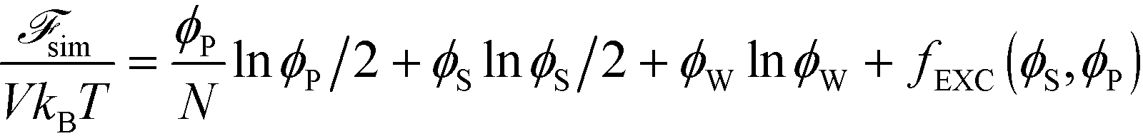 | (10) |
Here, V is the volume, kB is the Boltzmann constant, T is the temperature, and ϕW is the volume fraction of water. The first three terms describe the mixing entropy of the polymer, salt, and water, respectively. Inclusion of fEXC in eqn (10) links the molecular-level MC simulations to the field theory,69 and enables the direct determination of the binodal phase boundary as a function of ϕP and ϕS.
3 Transfer matrix coacervation theory
Previous work by the authors has established a molecularly-informed theory of complex coacervation,49 demonstrating near-quantitative matching to simulation phase diagrams and molecular structure. We again describe the underlying theory here, in order to provide the foundations for the remainder of the paper, but we refer the readers to the previous paper for detailed discussion and validation of this theory.49The premise of the transfer matrix coacervate theory is that, in highly charge-dense polyelectrolytes, nearly all of the polymer charges are immediately adjacent to a ‘condensed’ species of opposite charge. The process of coacervation is primarily due to the entropy associated with the combinations of those oppositely-charged species, which is governed by the surrounding salt and polymer concentrations.49 We map this situation to an adsorption model, where oppositely-charged polyelectrolytes and ions adsorb to a test polyelectrolyte ‘substrate’ (see schematic in Fig. 2).49 Each monomer on the test polyelectrolyte serves as an adsorption site, and we define a few possible ‘states’ for this site; a state C indicates a condensed counterion, a state P′ indicates that a new polymer has adsorbed, where all subsequent adsorbed polymers are of state P, and finally a state 0 indicates that there is no oppositely-charged, condensed species within a cutoff radius rC. We use a transfer matrix formalism to calculate the grand canonical partition function of this adsorption system, where the partition sum is calculated by the matrix calculation:
Ξ = ![[small psi, Greek, vector]](https://www.rsc.org/images/entities/i_char_e1ce.gif) T0MN T0MN | (11) |
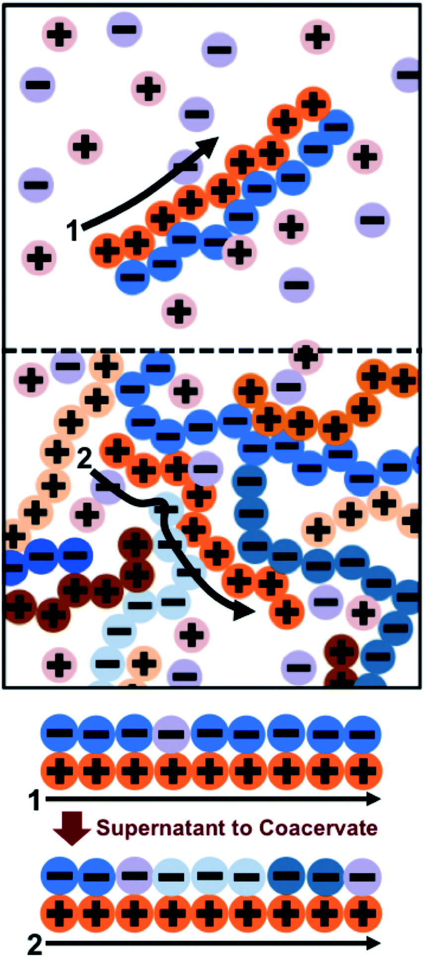 | ||
| Fig. 2 Schematic illustrating the transfer matrix theory of coacervation. We keep track of the environment around a test chain (orange polycation) by assigning neighboring charges as ‘adsorbed’ to the test chain. In the supernatant (1), these adsorbed charges are associated primarily with a single oppositely-charged polyelectrolyte partner with a few interspersed salt ions. In the coacervate (2), there are many neighboring polyelectrolytes and salt ions. The test chain prefers to be in the coacervate for entropic reasons; there are more configurations in state (2) due to the many adsorbing species. | ||
In this equation, is a column vector of Boltzmann weights for each possible state that the first adsorption site can take. Each successive multiplication of the transfer matrix M enumerates the Boltzmann weights for each possible state at each successive adsorption site, until the row vector T0 completes the partition summation. We define M by considering the weight associated with an adsorbed species at monomer ‘site’ si given the adsorbed species at site si−1:
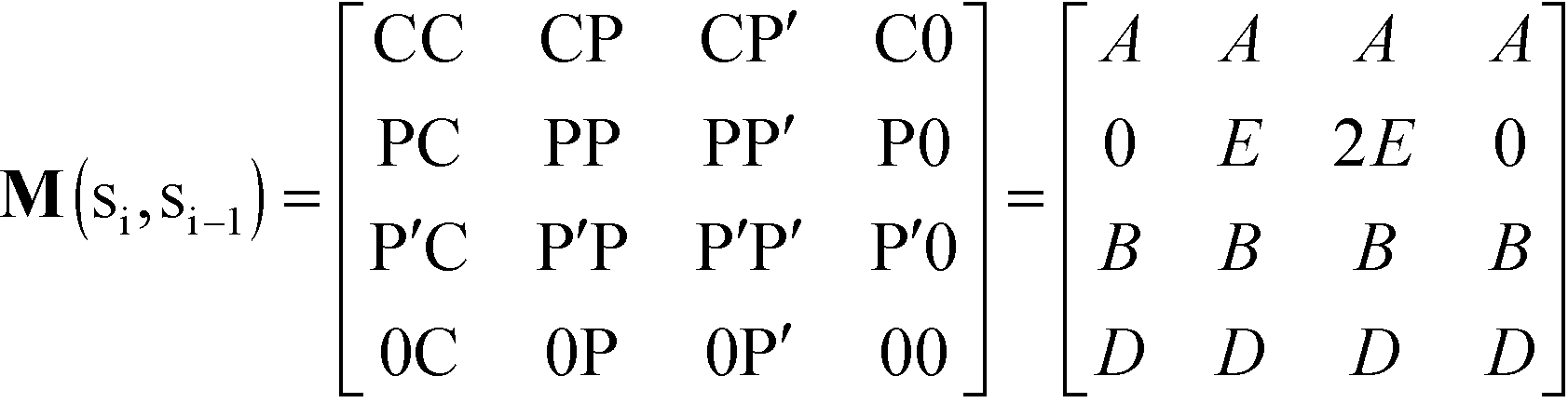 | (12) |
Pairs of adjacent sites are assigned to factors A = eμS/kBT, B = eμP/kBT, D = e−ε/kBT. μS is the salt chemical potential and μP is the polymer chemical potential, reflecting that these species are in chemical equilibrium with the surrounding coacervate system.49ε is an energy associated with having a vacant monomer, which is treated as a fit parameter.49 This parameter captures both the electrostatic driving force for counterion condensation, as well as short-range interactions such as those included in the traditional χ-parameter. E is the single-particle partition function associated with the subsequent confinement of adsorbed monomers after adsorption of an initial monomer.49
This form of the grand canonical partition function is solvable.49 The largest eigenvalue ξ of the transfer matrix dominates the partition function when N is sufficiently large, to yield an analytical form:
 | (13) |
A free energy of interaction between the polyelectrolyte monomers and the surrounding molecules can thus be calculated:
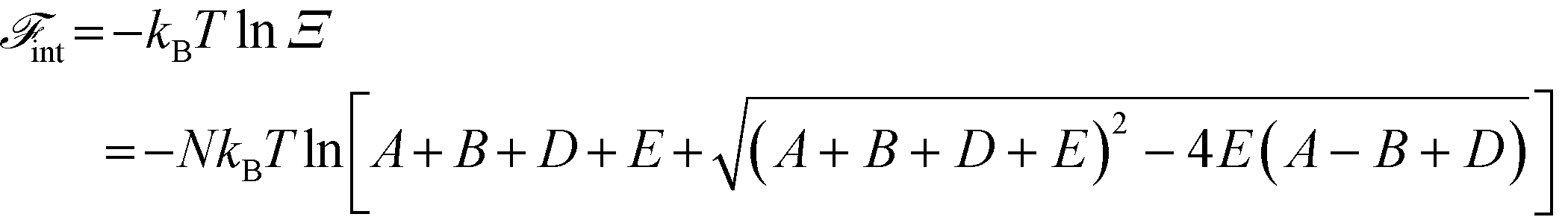 | (14) |
The chemical potentials used to determine A and B are ![[small mu, Greek, tilde]](https://www.rsc.org/images/entities/i_char_e0e0.gif) S = 0S + ln
S = 0S + ln![[thin space (1/6-em)]](https://www.rsc.org/images/entities/char_2009.gif) ϕS = ln(A0ϕS) and P = 0P + lnϕP = ln(B0ϕP), where the tilde represents normalization by kBT. 0S and 0P are the reference chemical potentials for the salt and polymer, and A0 = exp0S and B0 = exp0P.49 These expressions assume the local environment surrounding the chain is nearly ideal, consistent with simulations that show correlations do not extend significantly beyond the immediate neighbors of polyelectrolyte chains in the coacervate phase.20
ϕS = ln(A0ϕS) and P = 0P + lnϕP = ln(B0ϕP), where the tilde represents normalization by kBT. 0S and 0P are the reference chemical potentials for the salt and polymer, and A0 = exp0S and B0 = exp0P.49 These expressions assume the local environment surrounding the chain is nearly ideal, consistent with simulations that show correlations do not extend significantly beyond the immediate neighbors of polyelectrolyte chains in the coacervate phase.20
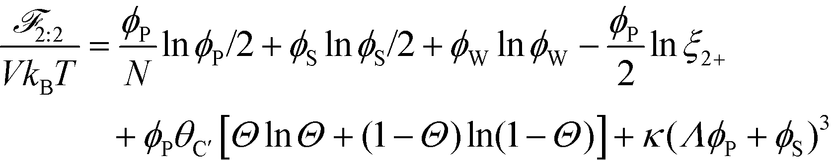
The free energy of coacervation can be defined by combining eqn (14) with the entropy of mixing for all species, and a phenomenological contribution capturing all non-water species' excluded volume:
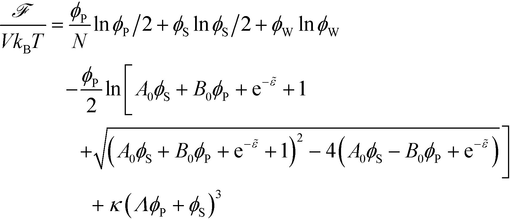 | (15) |
Here, κ determines the strength of the excluded volume interactions, and Λ = 0.6875 takes into account the lower excluded volume in connected polymer chains.
This theory is built on a few major assumptions that can limit the applicability of this formalism. First, this theory starts from the assumption that polymer charge density is sufficiently high that condensation via counterion or oppositely charged polyelectrolyte is almost always occurring;48,74 the value of D, which represents the absence of a condensed species, is parameterized to be small. The physical meaning of this parameter is related to the strength of counterion condensation, however it is not clear how to a priori determine this parameter. Another assumption is the simplified treatment of the salt ions in this theory. Outside of interactions with the polymer test chain, and their contributions to the excluded volume, we do not explicitly include salt-based electrostatic interactions. We justify this assumption for dense charges, because the weak electrostatics are heavily screened. However, it is not apparent that this would continue to hold especially in the limit that both ϕP and ϕS → 0. Finally, we neglect dielectric effects, which are known to play a significant role in the melt state,75–77 and can become significant in high salt-concentration solutions.74,78–83 In this work we neglect dielectric effects, due to the relatively high concentration of water in typical coacervate systems (>60%).21 The authors have previously observed qualitative agreements with experiment when neglecting dielectric effects,20 but true quantitative agreement may require including the effect of varying dielectric constants.
This model nevertheless captures both the molecular structure and phase behavior of the high charge-dense polymer complex coacervates in simulation,49 and thus compares favorably with experimental results.20,26 In this model, the primary driving force for coacervation is the configurational entropy of the bound species to the test chain (Fig. 2), which is larger when there are a large number of interacting charged species. Within the scope of the aforementioned approximations, we will demonstrate how modifications to this theory can provide conceptual insight into polymer physical features such as comb polymers and chain flexibility, as well as salt valency. For the rest of this paper, we note that determining the largest eigenvalue ξ as shown in eqn (13) is unnecessary; we instead use computation to directly calculate the matrix multiplication in eqn (11) and numerically determine the partition function Ξ in the more typical case that ξ does not have a simple, analytical form.
4 Results and discussion
We study comb polymer architecture, polymer stiffness, and salt valency by comparing to a baseline coacervate-forming system. Previous work by our group has used linear polymers with N = 100 and κθ = 3.3 kBT, which are shown to be well described by the transfer-matrix theory.49 For the transfer matrix theory, we use the values A0 = 20.5, B0 = 12.2, and D = 1.4.1 Chain stiffness
Coacervates can be made using a wide range of polymers and biopolymers,3 spanning highly flexible synthetic polymers such as poly(acrylic acid) to stiff polymers such as dsDNA. We can tune the polymer stiffness in our simulation model by adjusting the value of κθ, with larger values of κθ leading to stiffer polymers with longer persistence lengths. We are at high salt concentrations, so simulations show that the persistence length is almost exclusively governed by κθ and not salt or polymer concentration, due to the strong screening of electrostatics. We plot phase diagrams for κθ = 0.8 kBT to κθ = 13.0 kBT in Fig. 3a. In the flexible polymer limit κθ → 0, changes in κθ do not significantly affect phase behavior. This is also reflected in the salt partitioning, which is plotted in Fig. 3b. Here we use a parameter λ = ϕαS/ϕβS, which quantifies the depletion (λ < 1) of salt from the coacervate phase. This as a function of the supernatant salt concentration , which is normalized by the largest measured salt concentration (approximately the critical salt concentration).20,31 Larger values of the polyelectrolyte chain stiffness κθ (κθ ≥ 6.6 kBT) demonstrate significantly smaller two-phase regions and less salt depletion (i.e. larger λ) in the coacervate phase, when compared to smaller values of κθ.
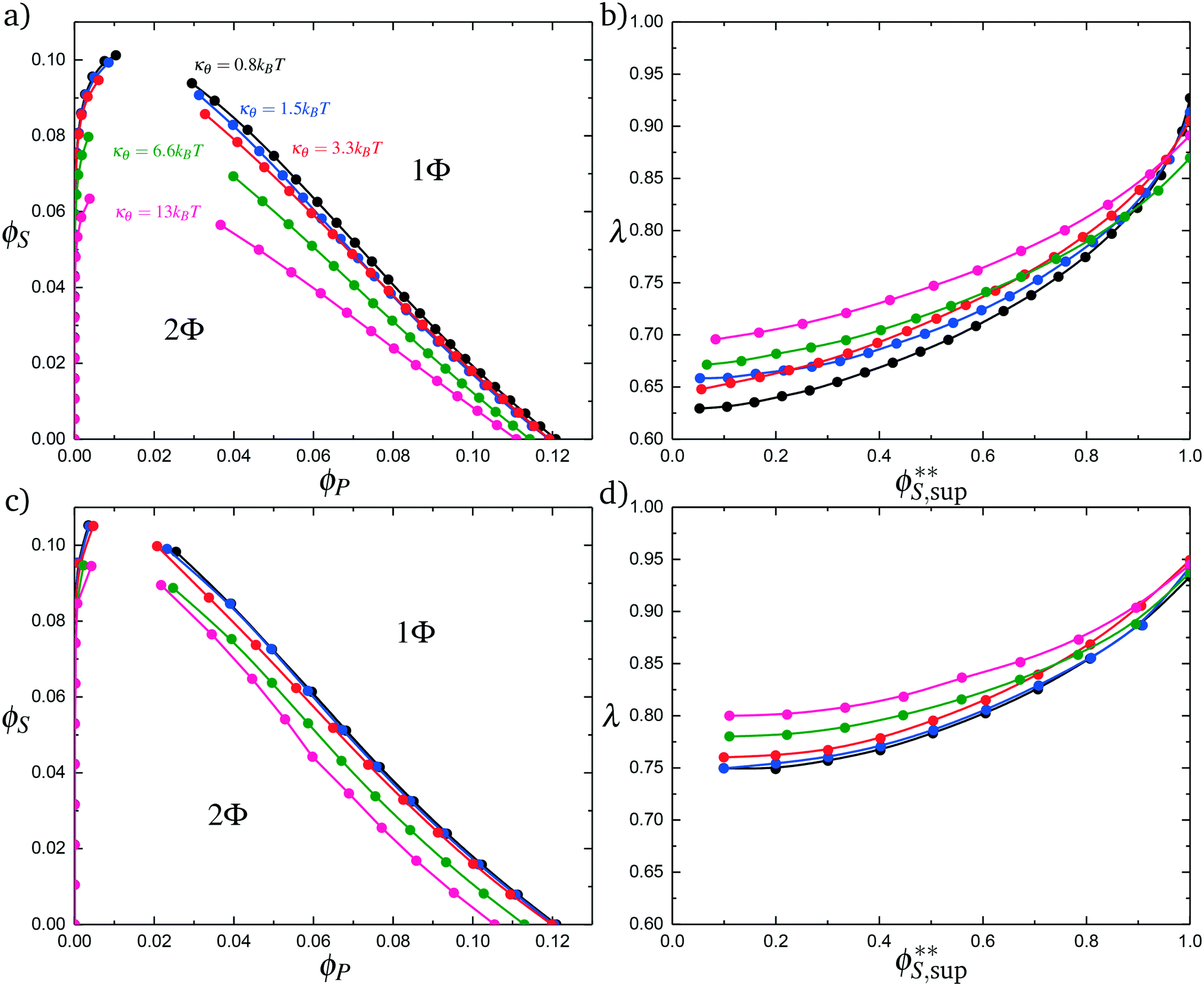 | ||
| Fig. 3 Coacervate phase behavior, with varying values of the chain stiffness κθ for both polyelectrolyte species. (a) Phase behavior as a function of ϕS and ϕP, calculated from simulation. As chain stiffness increases, the two-phase region begins to shrink. At small polymer flexibilities κθ < 6.6 kBT, these changes are modest, but much more stiff chains κθ < 6.6 kBT demonstrate significant changes in the location of the binodal. (b) The salt partitioning λ for all coacervation processes are such that there is less salt in the polymer-dense coacervate phase than the supernatant phase; concomitant with a decrease in the 2-phase region, this depletion of salt from the coacervate phase decreases in magnitude with an increase in stiffness κθ. We demonstrate qualitatively similar effects in our modified coacervate theory, for both phase behavior (c) and salt partitioning (d). Differences are apparent, likely reflecting the neglect of salt electrostatic contributions to the free energy that are not included in our current model. | ||
To understand this phase behavior from a molecular viewpoint, we consider the along-the-chain correlation of two neighboring, oppositely-charged polyelectrolytes. We assign adsorption states to all polymers in our MC simulations; each monomer has an environment characterized by the nearest unclaimed opposite charge within a cutoff radius rC = 1.5σ, so that it is in one of the states C, P′, P, or 0. We note that our results are not sensitive to the exact value of rC. We define the correlation function, CP′P:
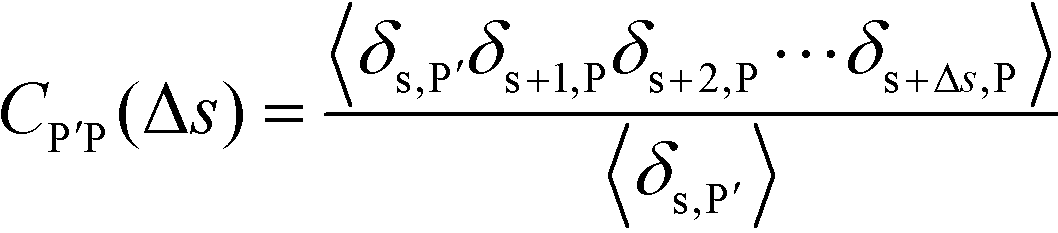 | (16) |
Here, δs,X = 1 if the state at adsorption site s is X, and δs,X = 0 otherwise. This correlation function quantifies the distribution of aligned segments along neighboring polyelectrolyte chains. Fig. 4a plots CP′P determined from simulation, and demonstrates that stiffness strongly affects this length distribution due to an increasingly slower decay of CP′P(Δs) as κθ is increased. For this plot, we chose ϕP = 0.09 and ϕS = 0.03, which is near the binodal curve for all values of κθ. This stiffness effect extends over all ϕP and ϕS values, which we demonstrate by considering a single related value CPP(Δs = 1,ϕS,ϕP) that is the propagation probability of a neighboring chain along the test polyelectrolyte. This is plotted Fig. 5 for as a function of both ϕS (Fig. 5a) and ϕP (Fig. 5b), which shows that CPP monotonically increases with κθ. This demonstrates that adsorbed chains tend to preferentially propagate when the chain is stiff (high κθ).
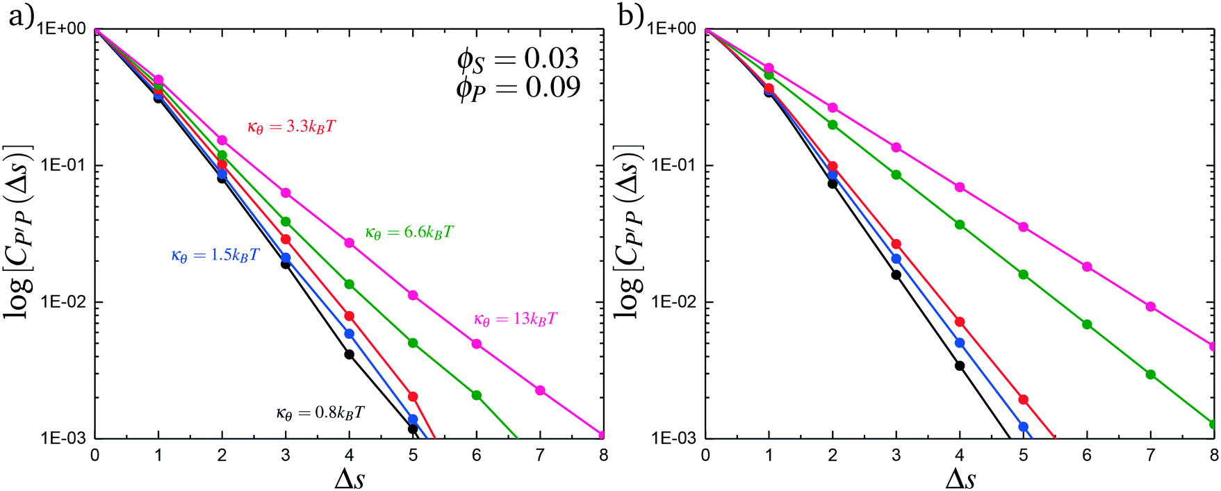 | ||
| Fig. 4 Our model attributes stiffness-related differences in coacervate phase behavior to longer runs of polycation/polyanion interactions for stiffer polyelectrolytes. These longer runs lead to a decrease in the number of polycation/polyanioninteractions, decreasing the entropic driving force for coacervates. We capture these longer runs in both simulation (a) and theory (b) by plotting the length distribution CP′P(Δs) of aligned polycation/polyanion segments for a coacervate near the binodal curve (ϕS = 0.03 and ϕP = 0.09). Both demonstrate the same qualitative trend, with larger values of κθ exhibiting longer runs of aligned polyelectrolytes. | ||
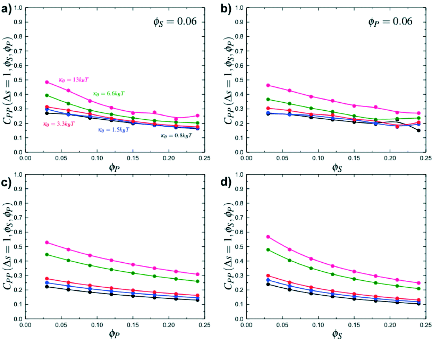 | ||
| Fig. 5 Simulation calculations of the probability of propagation CPP(Δs = 1,ϕS,ϕP) as a function of ϕP for ϕS = 0.06 (a) and as a function of ϕS for ϕP = 0.06 (b). Stiff polymers with large κθ are more likely to propagate along the chain, leading to longer runs of polycation/polyanion interaction for all salt and polymer concentrations, when compared to small κθ. Theory reproduces this observation, as demonstrated in (c) and (d) that are theoretical results for the same conditions as (a) and (b) respectively. | ||
We modify the transfer matrix theory to account for this chain alignment effect, informed by the increase in CP′P observed in simulation. Our conceptual argument is that, absent any competing polymers or counterions, which can ‘condense’ without significantly perturbing the original adsorbed polymer, the polymer can only either propagate or bend to allow an unbound state 0 at the next site. We propose a simple two-state model, based on the energy required to undergo this bending deformation, UB ∼ κθθ2/2 (see schematic in Fig. 6). We can thus write a relationship based on the conditional probabilities that a site has a state Y given the previous site has a state X, p(Y|X):
 | (17) |
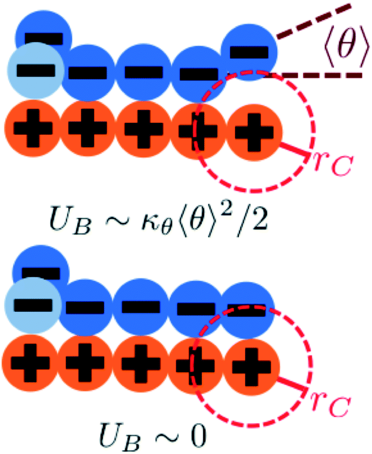 | ||
| Fig. 6 We consider a two-state model to determine the propagation of runs of polycation/polyanion interactions. A bent configuration (top) can end these runs, leading to the formation of a test chain monomer without a condensed opposite charge. This has an energetic penalty UB associated with κθ. The continuing propagation (bottom) does not have an energetic penalty UB ∼ 0. The relative weight of these choices is used to determine how κθ affects D and E in our model. | ||
We choose an average angle 〈θ〉 ∼ 0.7 that represents the extent of polymer bending in order for the next site is in state 0. This parameter is chosen within a reasonable range of θ to qualitatively match simulation. We assume that the adsorption statistics of competing polymers or counterions are not affected significantly by changes, so we calculate changes in transfer matrix quantities such that M(P,P) + M(0,P) = constant. This uniquely sets these respective values of the transfer matrix as a function of κθ. Finally, we make the assumption that we simultaneously decrease the likelihood of 0 due to rigidity even once the first monomer P′ is adsorbed; thus we equate M(0,P) + M(0,P′). We test this model by calculating the theoretical distribution of aligned segments CP′P (Fig. 4b) and CPP(Δs = 1,ϕS,ϕP) (Fig. 5c and d), qualitatively matching the corresponding simulation values. Fig. 3c and d demonstrate that the coacervation phase diagram and salt partitioning λ calculated from this theory qualitatively match simulations, based solely on these molecular correlation-informed changes in the transfer matrix.
This combination of simulation and theory provides conceptual insight into how stiffness affects complex coacervation. In the high charge-density limit, a primary driver of coacervation is the combinatoric entropy of each polyelectrolyte chain interacting with increasing numbers of oppositely-charged polyelectrolytes. The dilute supernatant has very few polyelectrolytes, because in this limit they exist as exclusive polycation/polyanion pairs. Stiffness affects the number of oppositely-charged polymers and counterions that a given test chain interacts with, due to the long, aligned runs of paired monomers. This lessens the entropic driving force for coacervation.
4.2 Comb polymer architecture
Comb polymers, where the branches are charged, have been investigated previously in experimental studies on coacervation.25 While comb polyelectrolytes can form coacervates when paired with linear counterparts, the two-phase region is significantly smaller than for coacervates formed from two linear polyelectrolytes.25 Preliminary simulation results from our group were parameterized to match these experimental observations.25We now study comb polyelectrolytes that are parameterized to match the polymer models used in this paper, and use theory to provide a mechanistic argument for this architectural effect. Fig. 7a demonstrates the phase diagrams for coacervates formed from a linear polyelectrolyte and a comb polyelectrolyte, with Nb = 3 and Nb = 5, compared to coacervates formed from two linear polyelectrolytes. In agreement with previous experiment and simulation,25 a decrease in branch length considerably shrinks the two-phase coacervation region of the phase diagram.
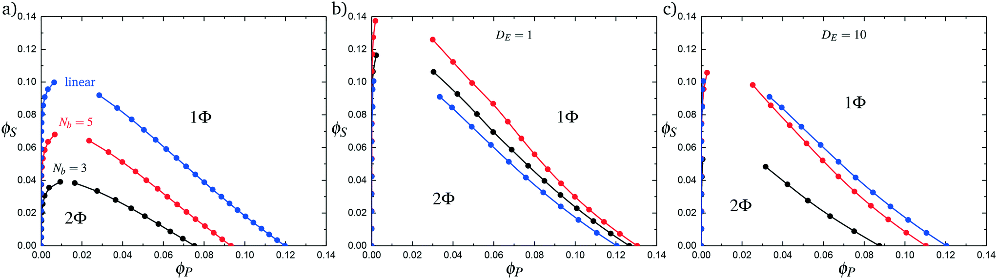 | ||
| Fig. 7 Complex coacervation phase behavior for branched polymers and linear polymers. (a) Simulation phase diagrams for Nb values of 3 (black) and 5 (red). A linear–linear system with an equivalent number of charged monomers is shown for comparison in blue. Comb polymers and linear polymers have a smaller immiscible region than an equivalent linear–linear system. (b) Phase diagrams generated from theory using increased values of Λ. This does not reproduce, even qualitatively, the immiscible region seen in simulation. (c) Considering decreased counterion condensation on the branch ends is necessary to observe the qualitative trends seen in simulations. | ||
We use transfer matrix theory to understand these drastic changes in the coacervate phase behavior of branched polymers. We consider a comb polymer to be equivalent to uncorrelated segments of length Nb. Each overall polymer still has only a single contribution to the translational entropy, however the individual branches interact as if they were shorter segments. To incorporate this into our theory, we rewrite the partition function for a test comb polymer as:
| Ξ = (ξ(Nb))N/Nb | (18) |
| ξ(Nb) = T0ME(sNb−1,sNb−2)⋯M(s3,s2)M(s2,s1)E | (19) |
In this case, we distinguish between the transfer matrices M and ME, with the latter representing a different transfer matrix that specifically considers the branch end. The vector E has also been changed from the in eqn (11) to account for the other end of the charged branch. To distinguish M and ME, and and E, we alter the weights for forming a vacant adsorption site (D → D × DE). This is a fit parameter that represents the effects of decreased counterion condensation at the ends of the branch.
Branch ends also play a role in excluded volume, via the parameter Λ in eqn (15). Λ accounts for the difference in the effective volume of polymer chains, which have overlapping spheres of excluded volume in our model. In previous work, we calculated this to be Λ = 0.6875. Branch ends are unconnected on one side, however, and have more accessible excluded volume. We calculate this to be ΛE = 0.8438. In the comb-linear coacervate systems, the effective excluded volume for the overall system is a weighted average 〈Λ〉 that is dependent on the relative ratio of branch ends to non-branch-end monomers. For our system, we find that 〈Λ〉 = [(NB − 1) Λ + ΛE]/NB.
In Fig. 7b we first demonstrate the effect of changing the excluded volume parameter Λ. Indeed, the increased excluded volume parameter 〈Λ〉 from branched polymers noticeably changes the two-phase coacervate region of the phase diagram; however, it is not sufficient to qualitatively reproduce the effects seen in simulation, and in fact leads to an increase in the two-phase coacervate forming region of the phase diagram. Instead, we require DE > 1 to demonstrate the decreased driving force for counterion condensation at the branch ends. This is shown in Fig. 7c for DE = 10, chosen to exhibit the same trends in phase behavior observed in simulations. This qualitatively demonstrates that decreased counterion condensation at branch ends leads to a significantly smaller two-phase coacervate region.
This mechanism is related to the combinatoric justification for the effect of stiffness on coacervation. For stiff polymers, longer runs of polyelectrolyte decrease the number of possible configurations that condensed species can have. In comb polymers, the mechanism is primarily related to the diminished condensation on branch ends. This similarly limits the number of possible configurations of condensed species, by making it increasingly likely that these adsorption sites are vacant and thus not contributing to the number of adsorption configurations. In both cases, either by increasing κθ or decreasing Nb, the end result is that there are fewer numbers of chain–chain interactions; this decreases the entropic driving force for coacervation, which is reflected in the simulation results.
4.3 Divalent Ions
We consider the case that one or both of the salt ions are divalent. Mutlivalent ions can present a challenge for polyelectrolyte theory, because they can exhibit behavior inconsistent with standard Poisson–Boltzmann theory. For example, DNA can be condensed with multivalent counterions,61 because electrostatic correlations induce like-charge attraction between DNA strands.66,67 This is just one of a whole range of correlation effects, including multivalent-induced brush collapse62,63 and like-charge attraction between surfaces.84 Coacervates exhibit significant electrostatic correlations, in particular due to the connectivity between polyelectrolyte charges; our transfer matrix theory includes this connectivity, and indeed we can extend this theory to describe the effects of divalent salt ions.To include divalent ions, we include a new possibility in the transfer matrix. Instead of having only a state (that we now call C′) to designate a bound counterion, we consider the possibility that the next monomer is also condensed with the same counterion (in a state we call C, see schematic in Fig. 8). We thus use the following matrix M2+(si,si−1), with the subscript 2+ denoting that the test polymer has divalent counterions:
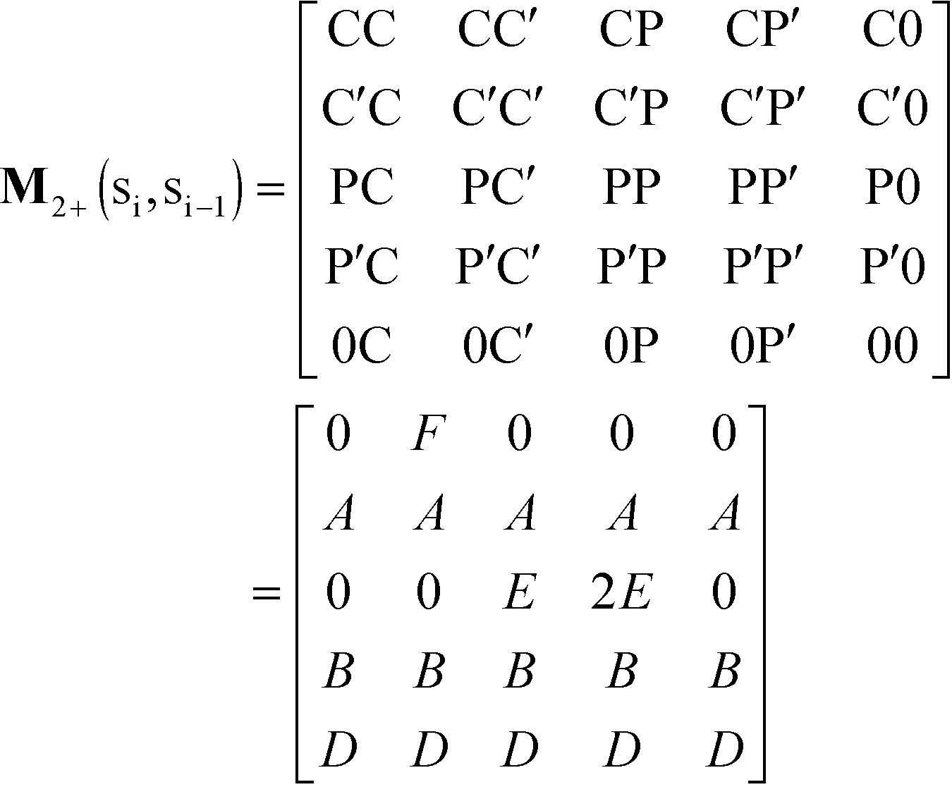 | (20) |
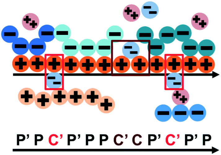 | ||
| Fig. 8 Our model for a polyelectrolyte interacting with divalent ions. We describe the environment around the test polycation (orange) as including adsorbed polyanions (P′ or P) or divalent ions (C′ or C). The first monomer with an adsorbed polymer is denoted with the prime (P′), following our previous notation.49 We now do this also for the divalent ions, which can only be adsorbed to a single polyelectrolyte monomer (singly adsorbed, with only a single C′, light red) or to two adjacent monomers (doubly adsorbed, with a C'C pair, dark red). | ||
This introduces the possibility that there are both singly- and doubly-adsorbed, divalent counterions. Singly-adsorbed divalent counterions only neutralize a single polyelectrolyte charge on a given chain, with the other charge neutralizing either a different polyelectrolyte or the oppositely charged ion (see light red boxes in Fig. 8). Doubly-adsorbed divalents neutralize an equivalent two charges on the polyelectrolyte (see dark red boxes in Fig. 8). The factor F is chosen to reproduce the balance of both singly- and doubly-adsorbed possibilities as determined by simulation. By introducing the two adsorption possibilities for the divalent counterions, an additional combinatorial entropy must be included to consider how the divalent counterions can be ‘chosen’ to be either singly or doubly-adsorbed. We define a fraction Θ of doubly-adsorbed divalent counterions, and use it to write a free energy expression for the divalent cation/divalent anion (2:2) case:
 | (21) |
Here, we define a test-chain partition Ξ2+ function as:
| Ξ2+ = T0MN2+ = ξN2+ | (22) |
Correspondingly, the value of Θ can be given by:
 | (23) |
lnξ2+/∂lnA) is the fraction of polymer sites with initially-adsorbed divalent ions. A similar expression can be derived for the free energy of a 2:1 salt, by replacing the −ϕPlnξ2+/2 term with −ϕP−lnξ2+/2−ϕP+lnξ/2, and including a factor of 1/2 on the divalent singly/doubly adsorbed entropy term. Here, only one of the two polyelectrolyte species includes the transfer matrix and entropic contribution associated with the divalent salt.
We test this model by comparing with simulation. Local correlations are described by the sequence of species adsorbed along the test molecule, and we specifically consider the probability of having a C′ immediately following another C′, p(C′|C′). This is plotted in Fig. 9 for both the 2:1 and 2:2 salt cases, as a function of ϕP (Fig. 9a) and ϕS (Fig. 9b). Both theory and simulation are plotted, demonstrating excellent agreement. We also consider the fraction of the adsorbed counterions that are doubly-adsorbed Θ, which can again be directly determined from simulation and calculated from theory. We plot Θ in Fig. 10, again with both 2:1 and 2:2 salts. Both theory and simulation match nearly quantitatively as a function of ϕP and ϕS.
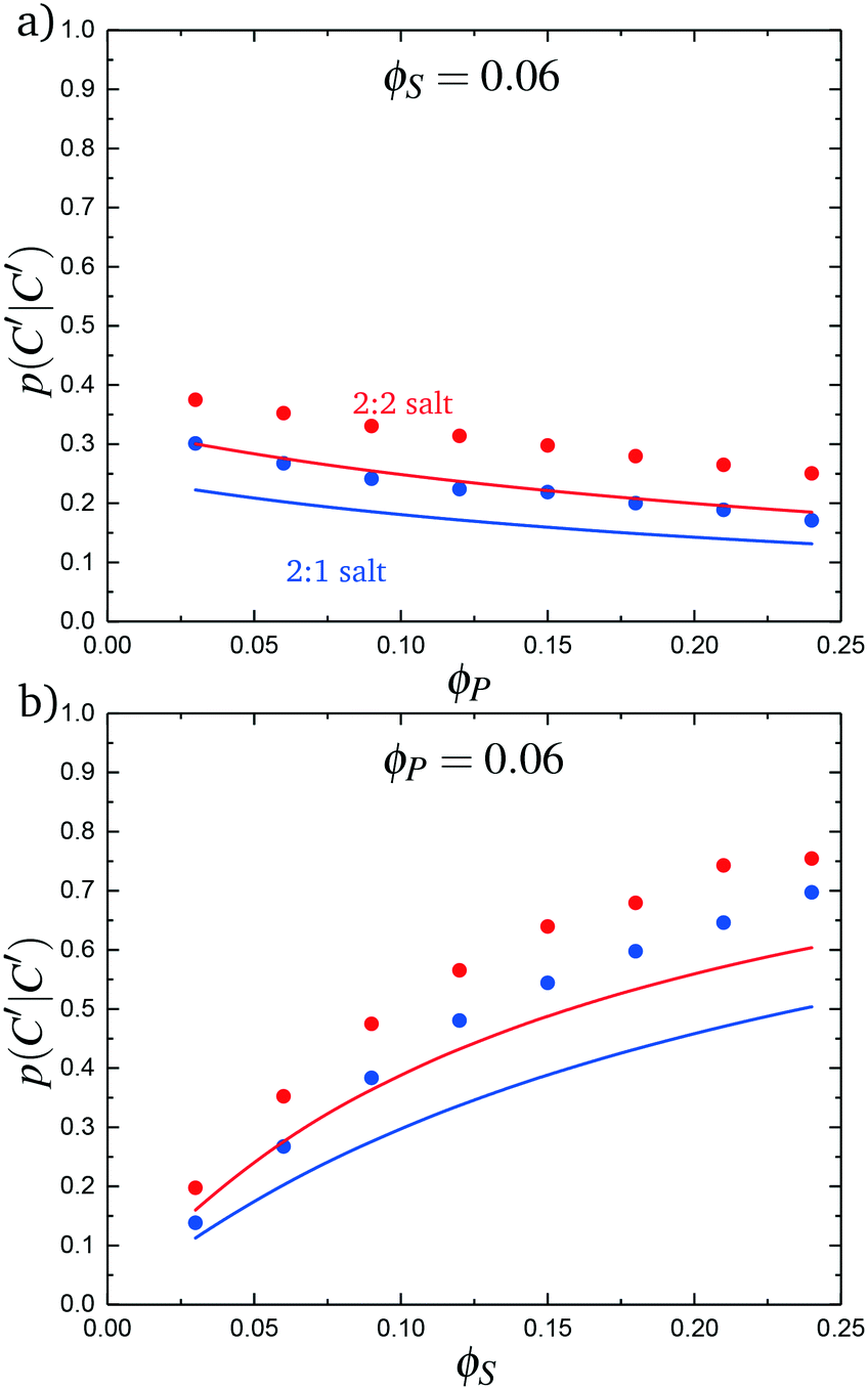 | ||
| Fig. 9 The probability of transitioning between singly-condensed salt ions, p(C′|C′), as a function of (a) ϕP and (b) ϕS. Points are simulation values and lines are theoretical calculations. | ||
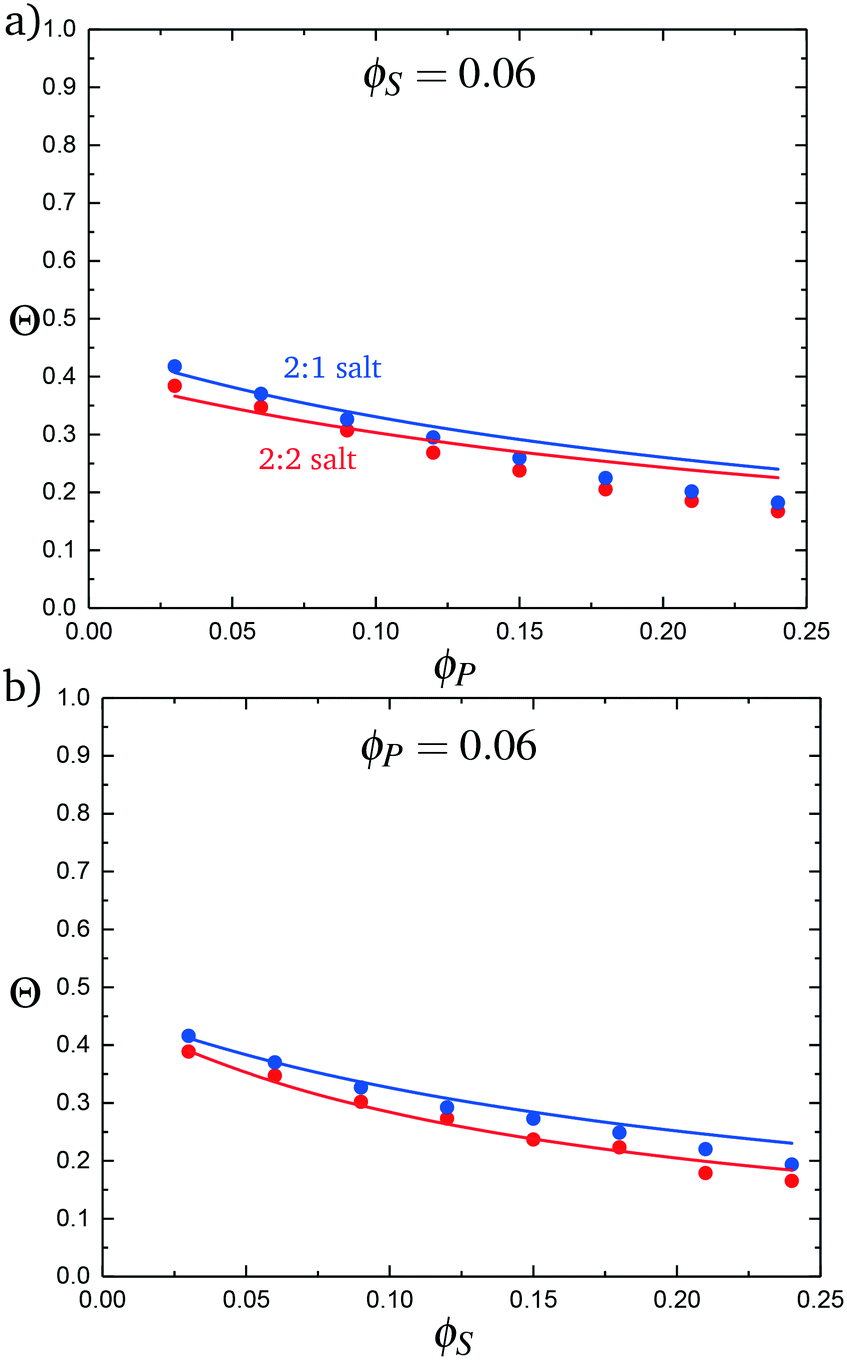 | ||
| Fig. 10 The probability of a salt ion double condensing, Θ, as a function of (a) ϕP and (b) ϕS. Points are simulation values and theoretical calculations are represented by lines. | ||
Fig. 11a plots phase diagrams in the ϕS − ϕP plane, calculated from simulation. Consistent with experimental observations,18 increased salt valency drastically decreases the two-phase coacervation region. Along with this decrease, there is a marked change in the salt partitioning. For 1:1 salts, λ < 1 indicates that salt is depleted from the coacervate phase. However, for 2:1 this depletion is significantly weaker and for 2:2 salts λ > 1, indicating that the divalent salts prefer the coacervate phase. Our theory reproduces these simulation observations, shown in Fig. 11c and d; we see the shrinking of the coacervation region upon inclusion of divalent salts, and also show that λ > 1 for 2:2 salts.
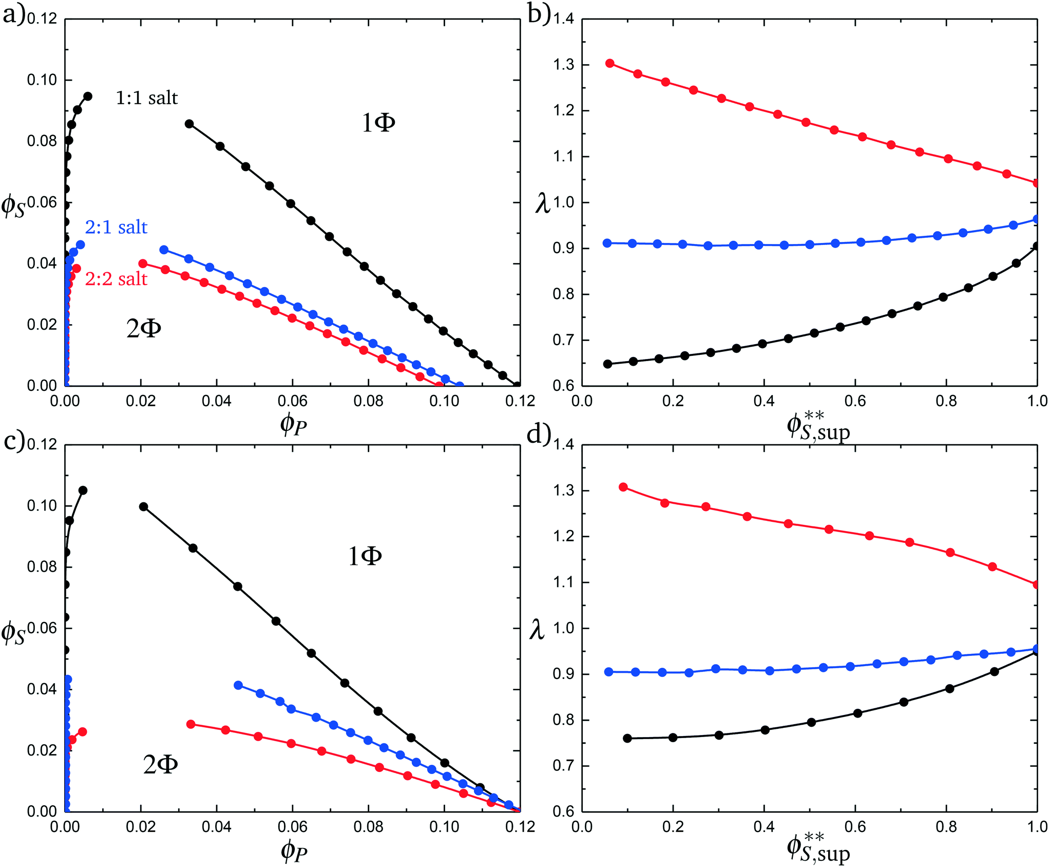 | ||
| Fig. 11 Complex coacervation phase diagrams with different salt valencies. (a) Simulation phase diagrams for a monovalent salt (1:1 black), a divalent salt (2:2 red), and a salt with one divalent species and one monovalent species (2:1 blue). Increased salt valency causes the immiscible region to shrink. (b) Simulation calculated salt partitioning for the various salt valencies. The 1:1 salt favors the supernatant phase as does the 2:1, but not to the same extent. The 2:2 salt favors the coacervate phase. (c) Theoretical phase diagrams for the various salt valencies. The same qualitative phase behavior is observed as seen in simulation. (d) Theoretically calculated salt partitioning shows the same qualitative trends as the simulation. This model of complex coacervation suggests the reason for the change in salt partitioning is due to ions double condensing onto the polymer chain. F, from the transition matrix M2+(si,si−1), has a value of 1.5, which was determined by matching simulation data. | ||
These observations are well-explained using an entropic argument. For monovalent (1:1) ions, entropy is increased during coacervation due to the increased configurations of polymers and ions that are adsorbed to the test chain. This entropic increases large with monovalent ions, because there are many configurations when a single charged monomer can be neutralized by a single salt ion. To contrast, a divalent ion neutralizes two charged monomers, significantly reducing the number of configurations of charged species adsorbed to the test chain. In this sense, a divalent ion is equivalent to two monovalent ions if those monovalent ions were constrained to be adsorbed next to each other along the chain. This decreases the entropic driving force for coacervation.
The inversion of λ, which shows that monovalent salt is depleted from the coacervate while divalent salt is depleted from the supernatant, is also entropically driven in theory. This is driven by the ϕPθC′[ΘlnΘ + (1 − Θ) ln(1 − Θ)] term in eqn (21), which accounts for the ways in which the adsorbed divalent charges can be neutralized by the surrounding polyelectrolyte chains. A given divalent charge is essentially only neutralized by individual opposite charges in the polymer-dilute supernatant, but in the coacervate any combination of polyelectrolyte or counterions can be used to neutralize the divalent charge.
Both of these effects are conceptually related to the behaviors of polyelectrolyte chains, with the divalent ion exhibiting behaviors analogous to a polyelectrolyte of length N = 2. For example, the phase behavior is similar to the effect of polyelectrolyte stiffness, where longer runs of aligned polyelectrolytes limit the number of adsorption configurations for the test chain. In the divalent case, the neutralization of two monomers at a time similarly limits the number of configurations and leads to less entropic driving force for coacervation. The entropic driving force for divalents to partition to the coacervate is also similar to the underlying driving force for coacervation, where the species (in this case the divalent ion, but in the coacervate case the polyelectrolyte) finds it entropically favorable to interact with many configurations of neighboring, oppositely charged species.
5 Conclusion
We have used a combination of simulation and theory to explore ways in which polymer physical features (chain stiffness, architecture, and salt valency) play a role in complex coacervation. We not only demonstrate that these features can have marked effects on coacervate phase behavior, but we use theoretical results to provide a mechanistic understanding of how molecular structure influences charged polymers. We show that this is related to how these molecular features affect the configurational entropy of condensation on test polymers. Phase behavior is indeed linked to the ‘number’ of species that are condensed, either via long runs of aligned polymer-polymer chains, via weak counterion condensation in short branches, or via divalent salt ions.These combinatoric principles have limitations, in particular outside the limit of high charge density. It is unclear how to systematically modify this theory for lower charge densities, and transition to coacervate theories that focus on charge fluctuation-driven attractions. We also note the limitations on the model due to simplifications of the salt interactions, which are not explicitly included except in a phenomenological cubic term to capture excluded volume. We justify this assumption due to the significant screening of these small molecule species, however we will have to reevaluate our assumptions if electrostatic interactions become stronger or short-range interactions become significant.
Despite these approximations, we capture how polymer physical behaviors influence coacervation for polyelectrolyte systems with experimentally relevant charge densities and electrostatic interaction strengths. This builds upon a simulation and theoretical model that qualitatively matches with experimental results in previous literature, and provides new physical intuition to guide experiment and molecular design in this active area of polymer research.
Conflicts of interest
There are no conflicts to declare.Acknowledgements
We thank financial support from an NSF CAREER Award (DMR-1654158), and use of the Extreme Science and Engineering Discovery Environment (XSEDE), which is supported by National Science Foundation Grant ACI-1053575.References
- H. G. Bungenberg de Jong and H. R. Kruyt, Proc. K. Ned. Akad. Wet., 1929, 32, 849–856 Search PubMed.
- J. T. G. Overbeek and M. J. Voorn, J. Cell. Comp. Physiol., 1957, 49, 7–26 CrossRef CAS.
- J. van der Gucht, E. Spruijt, M. Lemmers and M. A. Cohen Stuart, J. Colloid Interface Sci., 2011, 361, 407–422 CrossRef CAS PubMed.
- V. B. Tolstoguzov, Food Hydrocolloids, 1995, 9, 317–332 CrossRef CAS.
- A. Matalanis, O. G. Jones and D. J. McClements, Structured biopolymer-based delivery systems for encapsulation, protection, and release of lipophilic compounds, Adv. Colloid Interface Sci., 2011, 25, 1865–1880 CAS.
- C. Schmitt and S. L. Turgeon, Adv. Colloid Interface Sci., 2011, 167, 63–70 CrossRef CAS PubMed.
- R. J. Stewart, C. S. Wang and H. Shao, Adv. Colloid Interface Sci., 2011, 167, 85–93 CrossRef CAS PubMed.
- D. S. Hwang, H. Zeng, A. Srivastava, D. V. Krogstad, M. Tirrell, J. N. Israelachvili and H. J. Waite, Soft Matter, 2010, 6, 3232–3236 RSC.
- S. Lim, D. Moon, H. J. Kim, S. H. Seo, I. S. Kang and H. J. Cha, Langmuir, 2014, 30, 1108–1115 CrossRef CAS PubMed.
- M. A. Cohen Stuart, N. A. M. Besseling and R. G. Fokkink, Langmuir, 2004, 20, 2785–2791 CrossRef.
- D. V. Pergushov, A. H. E. Müller and F. H. Schacher, Chem. Soc. Rev., 2012, 41, 6888–6901 RSC.
- K. A. Black, D. Priftis, S. L. Perry, J. Yip, W. Byun and M. Tirrell, ACS Macro Lett., 2014, 3, 1088–1091 CrossRef CAS.
- S. Srivastava and M. V. Tirrell, Advances in Chemical Physics, John Wiley and Sons, Hoboken, NJ, 2016 Search PubMed.
- D. Priftis and M. Tirrell, Soft Matter, 2012, 8, 9396–9405 RSC.
- D. Priftis, N. Laugel and M. Tirrell, Langmuir, 2012, 28, 15947–15957 CrossRef CAS PubMed.
- D. Priftis, R. Farina and M. Tirrell, Langmuir, 2012, 28, 8721–8729 CrossRef CAS PubMed.
- D. Priftis, X. Xia, K. O. Margossian, S. L. Perry, L. Leon, J. Qin, J. J. de Pablo and M. Tirrell, Macromolecules, 2014, 47, 3076–3085 CrossRef CAS.
- S. L. Perry, Y. Li, D. Priftis, L. Leon and M. Tirrell, Polymer, 2014, 6, 1756–1772 CAS.
- S. L. Perry, L. Leon, K. Q. Hoffmann, M. J. Kade, D. Priftis, K. A. Black, D. Wong, R. A. Klein, C. F. Pierce III, K. O. Margossian, J. K. Whitmer, J. Qin, J. J. de Pablo and M. Tirrell, Nat. Commun., 2015, 6, 6052 CrossRef PubMed.
- M. Radhakrishna, K. Basu, Y. Liu, R. Shamsi, S. L. Perry and C. E. Sing, Macromolecules, 2017, 50, 3030–3037 CrossRef CAS.
- E. Spruijt, A. H. Westphal, J. W. Borst and M. A. Cohen Stuart, Macromolecules, 2010, 43, 6476–6484 CrossRef CAS.
- A. B. Kayitmazer, S. P. Strand, C. Tribet, W. Jaeger and P. L. Dubin, Biomacromolecules, 2007, 8, 3568–3577 CrossRef CAS PubMed.
- Q. Wang and J. B. Schlenoff, Macromolecules, 2014, 47, 3108–3116 CrossRef CAS.
- K. Q. Hoffman, S. L. Perry, L. Leon, D. Priftis, M. Tirrell and J. J. de Pablo, Soft Matter, 2015, 11, 1525–1538 RSC.
- B. M. Johnston, C. W. Johnston, R. Letteri, T. K. Lytle, C. E. Sing, T. Emrick and S. L. Perry, Org. Biomol. Chem., 2017, 15, 7630–7642 CAS.
- L.-W. Chang, T. K. Lytle, M. Radhakrishna, J. J. Madinya, J. Velez and C. E. Sing, Nat. Commun., 2017, 8, 1273 CrossRef PubMed.
- C. E. Sing, Adv. Colloid Interface Sci., 2017, 239, 2–16 CrossRef CAS PubMed.
- I. Michaeli, J. T. G. Overbeek and M. J. Voorn, J. Polym. Sci., 1957, 23, 443–449 CrossRef CAS.
- P. J. Flory, Principles of Polymer Chemistry, Cornell University Press, Ithaca, NY, 1953 Search PubMed.
- D. A. McQuarrie, Statistical Mechanics, University Science Books, Sausalito, 2000 Search PubMed.
- S. L. Perry and C. E. Sing, Macromolecules, 2015, 48, 5040–5053 CrossRef CAS.
- V. Y. Borue and I. Y. Erukhimovich, Macromolecules, 1990, 23, 3625–3632 CrossRef CAS.
- M. Castelnovo and J. F. Joanny, Eur. Phys. J. E: Soft Matter Biol. Phys., 2001, 1, 203–214 Search PubMed.
- J. Qin, D. Priftis, R. Farina, S. L. Perry, L. Leon, J. Whitmer, K. Hoffmann, M. Tirrell and J. J. de Pablo, ACS Macro Lett., 2014, 3, 565–568 CrossRef CAS.
- J. Qin and J. J. de Pablo, Macromolecules, 2016, 49, 8789–8800 CrossRef.
- A. Kudlay and M. O. de la Cruz, J. Chem. Phys., 2004, 120, 404–412 CrossRef CAS PubMed.
- A. Kudlay, A. V. Ermoshkin and M. O. de la Cruz, Macromolecules, 2004, 37, 9213–9241 CrossRef.
- D. J. Audus, J. D. Gopez, D. V. Krogstad, N. A. Lynd, E. J. Kramer, C. J. Haker and G. H. Fredrickson, Soft Matter, 2015, 11, 1214–1225 RSC.
- M. Radhakrishna and C. E. Sing, Macromol. Chem. Phys., 2016, 217, 126–136 CrossRef CAS.
- R. A. Riggleman, R. Kumar and G. H. Fredrickson, J. Chem. Phys., 2012, 136, 024903 CrossRef PubMed.
- J. Lee, Y. O. Popov and G. H. Fredrickson, J. Chem. Phys., 2008, 128, 224908 CrossRef PubMed.
- K. T. Delaney and G. H. Fredrickson, J. Chem. Phys., 2017, 146, 224902 CrossRef.
- J. Fu and J. B. Schlenoff, J. Am. Chem. Soc., 2016, 138, 980–990 CrossRef CAS PubMed.
- A. Salehi and R. G. Larson, Macromolecules, 2016, 49, 9706–9719 CrossRef CAS.
- S. Liu and M. Muthukumar, J. Chem. Phys., 2002, 116, 9975 CrossRef CAS.
- Z. Ou and M. Muthukumar, J. Chem. Phys., 2006, 124, 154902 CrossRef PubMed.
- R. Zhang and B. I. Shklovskii, Phys. A, 2005, 352, 216–238 CrossRef CAS.
- G. S. Manning, J. Chem. Phys., 1969, 51, 924–933 CrossRef CAS.
- T. K. Lytle and C. E. Sing, Soft Matter, 2017, 13, 7001–7012 RSC.
- A. Siber, A. L. Bozic and R. Podgornik, Phys. Chem. Chem. Phys., 2012, 14, 3746–3765 RSC.
- C. Forrey and M. Muthukumar, Biophys. J., 2006, 91, 25–41 CrossRef CAS PubMed.
- A. J. Spakowitz and Z.-G. Wang, Biophys. J., 2005, 88, 3912–3923 CrossRef CAS PubMed.
- R. M. Elder and A. Jayaraman, Macromolecules, 2012, 45, 8083–8096 CrossRef CAS.
- R. M. Elder, T. Emrick and A. Jayaraman, Biomacromolecules, 2011, 12, 3870–3879 CrossRef CAS PubMed.
- H. S. Antila, M. Harkonen and M. Sammalkorpi, Phys. Chem. Chem. Phys., 2015, 17, 5279–5289 RSC.
- H. S. Antila and M. Sammalkorpi, J. Phys. Chem. B, 2014, 118, 3226–3234 CrossRef CAS PubMed.
- M. Kim, H. R. Kim, S. Y. Chae, R. G. Larson, H. Lee and J. C. Park, J. Phys. Chem. B, 2013, 117, 6917–6926 CrossRef CAS PubMed.
- R. M. Elder and A. J. Jayaraman, J. Phys. Chem. B, 2013, 117, 11988–11999 CrossRef CAS PubMed.
- P. Welch and M. Muthukumar, Macromolecules, 2000, 33, 6159–6167 CrossRef CAS.
- J. Ruhe, M. Ballauff, M. Biesalski, P. Dziezok, F. Grohn, D. Johannsmann, N. Houbenov, N. Hugenberg, R. Konradi, S. Minko, M. MOtornov, R. R. Netz, M. Schmidt, C. Seidel, M. Stamm, T. Stephan, D. Usov and H. Zhang, Adv. Polym. Sci., 2004, 165, 79–150 CrossRef.
- L. C. Bosule and J. A. Schellman, Nature, 1976, 259, 333–335 CrossRef.
- B. K. Brettmann, N. Laugel, N. Hoffmann, P. Pincus and M. Tirrell, J. Polym. Sci., Part A: Polym. Chem., 2016, 54, 284–291 CrossRef CAS.
- B. Brettmann, P. Pincus and M. Tirrell, Macromolecules, 2017, 50, 1225–1235 CrossRef CAS.
- C. E. Sing, J. W. Zwanikken and M. Olvera de la Cruz, Macromolecules, 2013, 46, 5053–5065 CrossRef CAS.
- D.-W. Yin, F. Horkay, J. F. Douglas and J. J. de Pablo, J. Chem. Phys., 2008, 129, 154902 CrossRef PubMed.
- E. Raspaud, M. O. de la Cruz, J. L. Sikorav and F. Livolant, Biophys. J., 1998, 74, 381–393 CrossRef CAS PubMed.
- M. O. de la Cruz, L. Belloni, M. Delsanti, J. P. Dalbiez, O. Spalla and M. Drifford, J. Chem. Phys., 1995, 103, 5781–5791 CrossRef.
- D. Frenkel and B. Smit, Understanding Molecular Simulation: From Algorithms to Applications, Academic Press, San Diego, CA, 2002 Search PubMed.
- T. K. Lytle, M. Radhakrishna and C. E. Sing, Macromolecules, 2016, 49, 9693–9705 CrossRef CAS.
- J. P. Hansen and I. R. McDonald, Theory of Simple Liquids, Elsevier, Boston, 2006 Search PubMed.
- P. K. Jha, R. Sknepnek, G. I. Guerrero-Garcia and M. O. de la Cruz, J. Chem. Theory Comput., 2010, 6, 3058–3065 CrossRef CAS PubMed.
- J. Towns, T. Cockerill, M. Dahan, I. Foster, K. Gaither, A. Grimshaw, V. Hazlewood, S. Lathrop, D. Lifka, G. D. Peterson, R. Roskies, J. R. Scott and N. Wilkins-Diehr, Comput. Sci. Eng., 2014, 16, 62–74 CrossRef.
- S. K. Kumar, I. Szleifer and A. Z. Panagiotopoulos, Phys. Rev. Lett., 1991, 66, 2935–2938 CrossRef CAS PubMed.
- M. Muthukumar, J. Chem. Phys., 2004, 120, 9343–9350 CrossRef CAS PubMed.
- I. Nakamura, N. P. Balsara and Z.-G. Wang, Phys. Rev. Lett., 2011, 107, 198301 CrossRef PubMed.
- I. Nakamura, Soft Matter, 2014, 10, 9596–9600 RSC.
- R. Kumar, B. G. Sumpter and M. Muthukumar, Macromolecules, 2014, 47, 6491–6502 CrossRef CAS.
- A. Levy, D. Andelman and H. Orland, Phys. Rev. Lett., 2012, 108, 227801 CrossRef PubMed.
- X. Duan and I. Nakamura, Soft Matter, 2015, 11, 3566–3571 RSC.
- Y.-Z. Wei, P. Chiang and S. Sridhar, J. Chem. Phys., 1992, 96, 4569–4573 CrossRef CAS.
- R. Kumar and G. H. Fredrickson, J. Chem. Phys., 2009, 104901 CrossRef.
- E. Y. Kramarenko, I. Y. Erukhimovich and A. R. Khokhlov, Macromol. Theory Simul., 2002, 11, 462–471 CrossRef CAS.
- Y. A. Budkov, N. N. Kalikin and A. L. Kolesnikov, Eur. Phys. J. E: Soft Matter Biol. Phys., 2017, 40, 47 CrossRef PubMed.
- J. Zwanikken and M. Olvera de la Cruz, Proc. Natl. Acad. Sci. U. S. A., 2013, 110, 5301–5308 CrossRef CAS PubMed.
| This journal is © The Royal Society of Chemistry 2018 |