
 Open Access Article
 This Open Access Article is licensed under a
 Creative Commons Attribution 3.0 Unported Licence
Charge-controlled microfluidic formation of lipid-based single- and multicompartment systems†
Barbara
Haller
ab,
Kerstin
Göpfrich
 ab,
Martin
Schröter
ab,
Jan-Willi
Janiesch
ab,
Ilia
Platzman
*ab and
Joachim P.
Spatz
*ab
ab,
Martin
Schröter
ab,
Jan-Willi
Janiesch
ab,
Ilia
Platzman
*ab and
Joachim P.
Spatz
*ab
aDepartment of Cellular Biophysics, Max Planck Institute for Medical Research, Jahnstraße 29, 69120 Heidelberg, Germany. E-mail: Ilia.Platzman@mpimf-heidelberg.mpg.de; joachim.spatz@mpimf-heidelberg.mpg.de
bDepartment of Biophysical Chemistry, University of Heidelberg, Im Neuenheimer Feld 253, 69120 Heidelberg, Germany
First published on 26th July 2018
Abstract
In this manuscript, we introduce a simple, off-the-shelf approach for the on-demand creation of giant unilamellar vesicles (GUVs) or multicompartment synthetic cell model systems in a high-throughput manner. To achieve this, we use microfluidics to encapsulate small unilamellar vesicles in block-copolymer surfactant-stabilized water-in-oil droplets. By tuning the charge of the inner droplet interface, adsorption of lipids can be either inhibited, leading to multicompartment systems, or induced, leading to the formation of droplet-stabilized GUVs. To control the charge density, we formed droplets using different molar ratios of an uncharged PEG-based fluorosurfactant and a negatively-charged PFPE carboxylic acid fluorosurfactant (Krytox). We systematically studied the transition from a multicompartment system to 3D-supported lipid bilayers as a function of lipid charge and Krytox concentration using confocal fluorescence microscopy, cryo-scanning electron microscopy and interfacial tension measurements. Moreover, we demonstrate a simple method to release GUVs from the surfactant shell and the oil phase into a physiological buffer – providing a remarkably high-yield approach for GUV formation. This widely applicable microfluidics-based technology will increase the scope of GUVs as adaptable cell-like compartments in bottom-up synthetic biology applications and beyond.
Introduction
Compartments form the basis of all life by creating an enclosed space for controlled reactions to take place. Eukaryotic life, in particular, is characterized by the coexistence of a large outer compartment and organelles with segregated internal reaction volumes that enable spatial and temporal assembly of biological processes.1,2 An adequate compartment system is thus indispensable for the bottom-up construction of functional modules for synthetic cells. In the past decades, various compartment-based systems have been developed and used as model systems in synthetic biology. These include lipid-based vesicles,3,4 coacervates,5,6 proteinosomes,7,8 polymersomes9,10 and water-in-oil droplets.11,12 The gold standard, however, remains lipid-based giant unilamellar vesicles (GUVs), due to their close resemblance to natural cell membranes.Currently, electroformation13 and gentle hydration14 are the most commonly used methods for creating GUVs. However, low GUV yields in physiological buffer solutions, being heterogeneous in GUV's size and lipid composition, strong limitations to small amounts of charged lipids (<10%) and low efficiency biomolecule encapsulation remain the major drawbacks of these methods towards realizing a synthetic cell.15–17 Other methods like microfluidic jetting18 or emulsion transfer19 overcome these limitations to some extent, but compromise the GUV yield.
Recently, microfluidic technologies for the high-throughput production of monodisperse GUVs and vesosomes have been developed.20–23 Using capillary-based microfluidics and dewetting of double emulsion droplets, Deng et al.22 achieved precise control over the number of compartments and their encapsulated content. However, the major disadvantage of this technology is that the compartments cannot be manipulated after their formation. Weiss et al.20 demonstrated the formation of the so-called droplet-stabilized GUVs (dsGUVs), which consisted of a spherical lipid bilayer that was encapsulated within a water-in-oil droplet, which in turn was stabilized by a custom-synthesized block-copolymer surfactant. The enhanced mechanical stability of the dsGUVs allows for their bottom-up, step-by-step loading with desired biomolecules by microfluidic picoinjection.24 After picoinjection, free-standing GUVs can then be released from the droplet into a physiological aqueous environment, ridding them of both the oil phase and the surfactant shell without leaving any detectable surfactant or oil residues behind.
In hindsight, the development of 2D-supported lipid bilayers was a true game changer in research areas ranging from biointerfaces and membrane biology to physics and biotechnology, because it contributed to numerous scientific and technological developments.25 The technology developed by Weiss et al. for creating 3D lipid bilayers supported by micrometer-size droplets has the same potential; however, to pave the way towards the widespread utilization of dsGUVs, the mechanism of their formation has to be thoroughly characterized and standardized.
Here, we demonstrate a method to tailor the interaction between the interface of surfactant-stabilized water-in-oil droplets and lipid vesicles for the formation of multicompartment systems, dsGUVs, or a combination of the two. In principle, multicompartment systems mimic the basic architecture of eukaryotic cells. These are obtained by controlling the charge density on the droplet interface by mixing two commercially available fluorosurfactants in different molar ratios: an uncharged poly(ethylene glycol) (PEG)-based fluorosurfactant and a negatively charged perfluoropolyether (PFPE) carboxylic acid fluorosurfactant (Krytox). The pure PEG-based surfactant inhibits the interaction between small unilamellar vesicles (SUVs) and the droplet interface, resulting in a pure multicompartment system. Subsequent addition of Krytox triggers the charge-driven formation of dsGUVs. The control of the charge appeared to be essential for well-controlled formation of GUVs of different compositions. We characterize the transition between multicompartment systems and dsGUVs in relation to Krytox concentration, lipid composition, and GUV release efficiency. This straightforward and highly transferable technique for the creation of customizable compartments is ideal for use in bottom-up synthetic biology applications.
Materials and methods
Materials
Lipids used in this study: 1,2-dioleoyl-sn-glycero-3-phosphocholesteroline (DOPC), 1-palmitoyl-2-oleoyl-sn-glycero-3-phosphocholesteroline (POPC) and 1,2-dioleoyl-sn-glycero-3-phospho-(1′-rac-glycerol) (DOPG) were purchased from Avanti (Avanti Polar Lipids, USA); ATTO 488 1,2-dioleoyl-sn-glycero-3-phosphoethanolamine (ATTO 488 DOPE) was purchased from ATTO TEC (Siegen, Germany). All lipids were stored in chloroform at −20 °C and used without further purification. Cholesterol C8667 and a perfluoro-1-octanol (PFO) de-emulsifier were purchased from Sigma-Aldrich (Sigma-Aldrich, Germany). Perfluoropolyether–polyethylene glycol (PFPE–PEG) block-copolymer fluorosurfactants (PEG-based fluorosurfactants) were purchased from Ran Biotechnologies (Lot# 018-050, RAN Biotechnologies, Inc., USA). PFPE-carboxylic acid (Krytox, MW 7000–7500 g mol−1) and HFE-7500 fluorinated oil were purchased from DuPont (DuPont, Germany) and 3M (3M, Germany), respectively. Double sided sticky tape (90 μm thickness) was purchased from Tesa (TESA SE, Germany), and rhodamine 6G and Nile red were obtained from Sigma-Aldrich (Sigma-Aldrich, Germany).Multicompartment system and dsGUV formation
For the formation of multicompartment systems and dsGUVs, solutions of SUVs with different lipid compositions were generated according to previously reported protocols.20 In brief, the lipids were mixed at desired ratios in a glass vial and dried under a gentle stream of nitrogen. To remove traces of the solvent, the lipids were kept under vacuum in a desiccator for at least 2 h. The dried lipids were resuspended to a concentration of 2.2 mM in 30 mM Tris buffer at pH 7.4 (storage buffer) and the resulting SUV solution was then extruded 7 times through a polycarbonate filter with a pore size of 50 nm (Avanti Polar Lipids, Inc.). The mean SUV diameter was determined to be 68 ± 15 nm (ESI,† Fig. S1) using dynamic light scattering (DLS, Malvern Zetasizer (Nano ZS). In some cases partial lipid aggregation could be observed. Solutions containing SUVs were stored at 4 °C for up to 48 h or encapsulated in microfluidic droplets immediately.Droplet-based microfluidic devices made of PDMS (Sylgard 184, Dow Corning, USA) were utilized to form multicompartment systems or dsGUVs. The PDMS devices were produced as previously described using photo- and soft-lithography methods (ESI,† Fig. S2).20,26 With a nozzle diameter of 20 μm, the device is suitable for the production of droplets ranging from around 25 μm to 45 μm, depending on the flow rate settings. For the purpose of this study, the flow rate of the water and oil phases was set to 200 μl h−1 and 2000 μl h−1, respectively. These produced phospholipid-containing droplets with a diameter of 30 μm at a rate of 4.2 kHz.
The SUV solution was diluted to a final lipid concentration of 1.1 mM (equivalent to 26.5 μM SUVs/1.6 × 1016 SUVs per ml), so as to form a continuous lipid bilayer within the droplets that were 30 μm in diameter.20 To create dsGUVs containing free-floating SUVs in the droplet volume, a lipid concentration of 2.2 mM (equivalent to 53 μM SUVs/3.2 × 1016 SUVs per ml) was used. Finally, the SUVs were introduced into the aqueous channel of the microfluidic device for droplet formation. The oil phase consisted of HFE-7500 oil including 1.4 wt% PFPE–PEG-based fluorosurfactants and Krytox at concentrations ranging from 0.15 to 15 mM. PUMP 11 ELITE syringe pumps (Harvard Apparatus, USA) were used to control the flow rates, which were set to 200 and 2000 μL h−1 for the aqueous and oil phases, respectively. Water-in-oil droplets containing the SUV solution were created at the flow-focusing junction, the place where the aqueous phase encounters the surfactant-containing oil phase (ESI,† Fig. S2). Droplets were collected in a microtube and transferred into observation chambers built from two cover slips (Fisher Scientific) glued together using double-sided sticky tape as a 90 μm thick spacer.20 The chambers were filled with the oil phase and sealed with two-component glue (Twinsil, Picodent). A Leica SP5 confocal microscope (Leica Microsystems, Germany) equipped with an argon laser and a white light laser was used for imaging immediately after compartment formation and after 7 days storage at 4 °C to assess compartment formation and stability. Imaging was carried out using a 63× oil-immersion objective lens (HCX PL APO 63×/1.40–0.60; Leica Microsystems GmbH, Germany). The pinhole for data acquisition was set to 1 Airy unit, which corresponded to an Airy disk diameter of 96 μm and a thickness of 0.9 μm of the optical slice. Moreover, fluorescence recovery after photobleaching (FRAP) was carried out to characterize the bilayer formation. Experimental conditions are described in more detail elsewhere.20 Additionally, droplets sealed in a microfluidic trapping device were imaged under the same conditions.
Cryo-scanning electron microscopy (cryo-SEM)
For cryo-SEM sample preparation, the droplet emulsion solution (3 μl) was dropped onto 0.8 mm diameter gold specimen carriers assembled on a freeze fracture holder (Leica Microsystems, Wetzlar, Germany) and immersed immediately in liquid nitrogen. Next, the droplets were transferred using an evacuated liquid nitrogen-cooled shuttle (Leica EM VCT100, Leica Microsystems, Wetzlar, Germany) into a Leica EM BAF060 (Leica Microsystems, Wetzlar, Germany) freeze fracture and etching system. For cryo observations the droplets were fractured in a 10−6–10−7 mbar vacuum chamber at −160 °C with a cooled knife. To allow for the sublimation of water in the fractured droplets, the sample holder stage was heated to −90 °C for 60 min. Following sublimation, the freeze fractured droplets were coated with 4 nm of Pt–C by electron beam evaporation. For image acquisition, the samples were transferred via an evacuated liquid nitrogen cooled shuttle into the imaging chamber of a Zeiss Ultra 55 field emission electron microscope (FE-SEM) equipped with in-lens, secondary electron (SE) and angle selective backscattered electron (ASB) detectors (Zeiss SMT, Oberkochen, Germany). Top-view imaging was performed under low temperature conditions (top = −115 ± 5 °C) and with a working distance between 3 to 5 mm. Due to the low conductivity of the emulsion droplets low acceleration voltages of 1.5–2.0 kV were used. Signals were detected with the in-lens detector.Infrared (IR) and MALDI mass spectrometry (MS) measurements
IR and MALDI MS measurements were performed to assess the purity of the commercially available PEG-based fluorosurfactants. IR measurements were conducted on a Nicolet Nexus 870 Fourier transform infrared spectrophotometer (Thermo Electron GmbH, Dreieich, Germany). The FTIR spectrum obtained from the 10 wt% PEG-based fluorosurfactants show no band at 1777 cm−1, which is attributed to a stretching mode of the C![[double bond, length as m-dash]](https://www.rsc.org/images/entities/char_e001.gif) O band of Krytox (ESI,† Fig. S3A).27 However, the FTIR spectrum obtained from the pure PEG-based fluorosurfactants (ESI,† Fig. S3B) reveals a tiny band at 1777 cm−1.
O band of Krytox (ESI,† Fig. S3A).27 However, the FTIR spectrum obtained from the pure PEG-based fluorosurfactants (ESI,† Fig. S3B) reveals a tiny band at 1777 cm−1.
MS measurements confirmed the presence of Krytox molecules in the PEG-based fluorosurfactants (ESI,† Fig. S4). Moreover, the MS spectra allowed for estimation of the molecular weight of the block-copolymers. This made it possible to calculate the concentration range of 3.8 to 5.7 mM PEG-based fluorosurfactants, which corresponded to 1.4 wt%. MS measurements were performed using a MALDI-TOF MS system (AXIMA Performance, Shimadzu, Japan). Spotting was done by overlaying one spot of a stainless-steel plate with 0.5 μl 1,8,9-trihydroxyanthracene (THA; 10 mg ml−1) in 1,1,1,3,3,3-hexafluoro-2-propanol (HFIP). Immediately after drying at ambient temperature, the spot was covered with 2 μl of a mixture of surfactant (1 mg ml−1 in HFIP), THA (10 mg ml−1 in HFIP) and LiTFA (100 mM in HFIP) in a volume ratio of 10![[thin space (1/6-em)]](https://www.rsc.org/images/entities/char_2009.gif) :1:1 and left to dry at ambient temperature. Afterwards, the spot was lined with 1 μl THA (10 mg ml−1 in HFIP).
:1:1 and left to dry at ambient temperature. Afterwards, the spot was lined with 1 μl THA (10 mg ml−1 in HFIP).
Partitioning experiment
Partitioning experiments were performed to examine the accumulation of Krytox molecules at the water–oil interface.28 Towards this end, 1 ml of HFE-7500 oil that contained Krytox concentrations between 0 and 1 mM (with and without 1.4 wt% PEG-based fluorosurfactants) was added to a 3.5 ml cuvette. Tris buffer (30 mM Tris and 10 mM MgCl2) containing rhodamine 6G (1 mM Rho6G) was gently pipetted on top of the oil solutions. Due to the 1:1 chemical interaction between the Krytox molecules and Rho6G, partitioning of Rho6G molecules to the oil phase was observed (ESI,† Fig. S5A). Following 48 h of incubation, samples from the oil and aqueous phases were carefully collected and transferred into a 96 well plate. The Rho6G content was determined in a plate reader (Infinite 200, Tecan) by measuring the absorbance at 500 nm (ESI,† Fig. S5B). The analysis of the partitioning experiment revealed that 1.4 wt% PEG-based fluorosurfactants contain approximately 0.04 mM free Krytox. This concentration is orders of magnitude lower than the 3.8–5.7 mM PEG-based fluorosurfactants, which is estimated to correspond to the 1.4 wt% weight based on the MS spectra (ESI,† Fig. S4).
Interfacial tension measurements
A contact angle system OCA (DataPhysics, USA) with a CCD high-speed camera HS, which was turned 90° (DataPhysics, USA) and which was capable of pendant drop measurements, was used to determine the interfacial tension (IFT) of aqueous droplets stabilized by PEG-based fluorosurfactants and Krytox dissolved in HFE-7500 oil. The Young–Laplace equation was chosen to fit the droplet shape in order to determine the IFT values. The aqueous solution, consisting of 1 mM MgCl2 dissolved in freshly deionized water (R = 18 MΩ, Milli-Q filtered), was poured into a glass cuvette and renewed after each measurement. A stable oil droplet was generated manually using a syringe. IFT values were recorded until a stable value was reached. When the IFT values fell below 1 mN m−1 and stable droplet creation was not possible, values were set to 0 mN m−1.GUV release into a physiological environment
After formation, dsGUVs were collected from the outlet of the microfluidic chip in a microtube (Eppendorf, Germany). The collected droplets were stored at 4 °C overnight for equilibration of the lipid and the ionic conditions within the droplets.To release the GUVs from the oil phase and from the stabilizing polymer shell into an aqueous environment, 50 μl of 30 mM Tris buffer supplemented with 10 mM MgCl2 (matching the osmolarity of the encapsulated aqueous phase) was pipetted onto the droplet emulsion. To destabilize the droplets, 10–100 μl of 30 vol% PFO-containing HFE-7500 oil was slowly added until the milky emulsion turned into a clear aqueous phase (monitored by the naked eye). Following de-emulsification, the released GUVs were carefully removed with a pipette and transferred into observation chambers coated with BSA (bovine serum albumin, SERVA Electrophoresis GmbH). Cover slides were incubated with PBS containing 1 mg ml−1 BSA for 2 h at RT and then washed twice with PBS and Milli-Q water. Confocal imaging was performed after 1 h to allow for sedimentation of the GUVs to the bottom of the chamber. For statistical analysis (ESI,† Fig. S6), GUVs were counted, but only GUVs with diameters >20 μm were taken into account.
Results and discussion
Formation of multicompartment systems
The formation of multicompartment systems requires strategies to inhibit the interaction between the inner shell of the surrounding compartment and the encapsulated SUVs, so that the latter remain scattered within the compartment volume. To achieve this, we set out to create droplets with an inert inner surface and encapsulate SUVs within their lumen. Fluorescently labeled SUVs (in 30 mM Tris, 10 mM Mg2+) are encapsulated into water-in-oil droplets that are stabilized by pure uncharged PEG-based fluorosurfactants (see the Materials and methods section) using a microfluidic droplet production device (ESI,† Fig. S2A). As shown in Fig. 1A, the encapsulated SUVs are homogeneously distributed within a droplet. The inert and uncharged PEG on the inner droplet interface29 inhibits the interaction between the SUVs and the droplet, resulting in a stable multicompartment system. This multicompartment system provides a spatially confined space to observe and analyze SUV-based functional modules which structurally mimics organelles in real cells.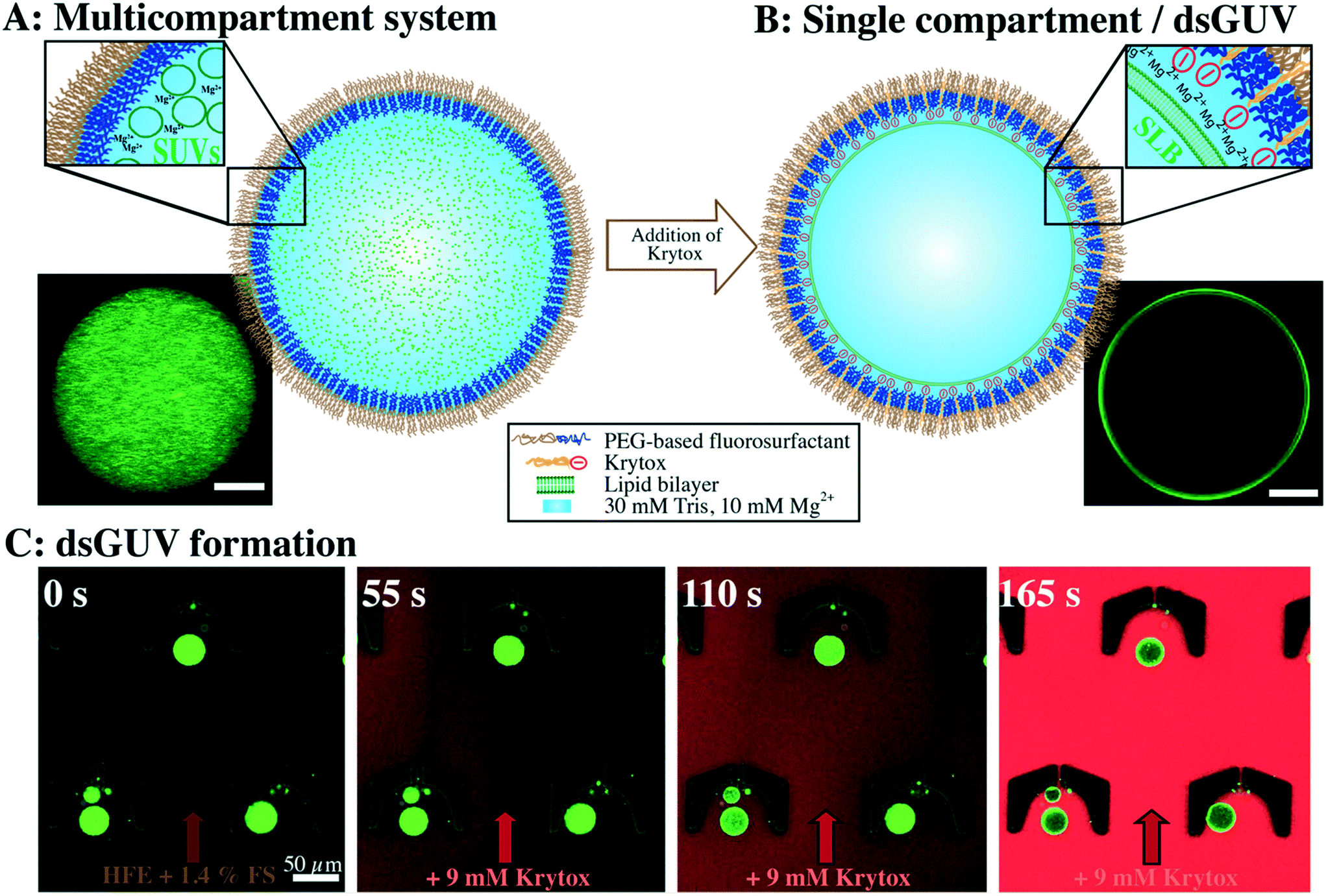 | ||
| Fig. 1 Controlled formation of multicompartment systems or dsGUVs depending on the surfactant charge in the oil phase. A) Sketch (upper inset) and the corresponding representative confocal fluorescence image (lower inset) of SUVs (in 30 mM Tris, 10 mM Mg2+) encapsulated in a water-in-oil droplet stabilized by inert PEG-based fluorosurfactants without Krytox. The confocal image shows the lipids of homogeneously distributed SUVs emitting green fluorescence (42.25% DOPC, 42.25% POPC, 15% cholesterol and 0.5% ATTO 488-labeled DOPE). B) Krytox addition (9 mM) to the surrounding oil leads to dsGUV formation. The corresponding, representative confocal image (lower inset) shows green fluorescence from lipids (42.25% DOPC, 42.25% POPC, 15% cholesterol and 0.5% ATTO 488-labeled DOPE) visible at the periphery of the droplet. C) Time-lapse analysis of dsGUV formation (42.25% DOPC, 42.25% POPC, 15% cholesterol and 0.5% ATTO 488-labeled DOPE) in a microfluidic trapping device. Time point 0 s: droplets are trapped in PDMS cavities by applying a constant flow of HFE-7500 oil containing PEG-based fluorosurfactants (FS). After 55 s: addition of HFE-7500 oil containing Krytox (9 mM). For clarity, the oil containing Krytox was labeled with 10 nM Nile red. After 110 s: attraction of SUVs to the droplet periphery. After 165 s: the accumulation of lipids on the droplet periphery is visible as a bright ring in the confocal plane. This indicates successful dsGUV formation. Scale bars: 50 μm. | ||
Formation of dsGUVs
For dsGUV formation – in other words, the emergence of one large GUV that is supported by a block-copolymer surfactant shell through fusion of the SUVs to the droplet interface20 – an electrostatic interaction between the SUVs and the droplet periphery is required. For this purpose, a negatively-charged surfactant (namely Krytox, a PFPE-carboxylic acid) was mixed with PEG-based fluorosurfactant-containing HFE 7500 oil. Both surfactants assemble at the droplet periphery in a competitive manner. We find that concentrations of greater than 3 mM Krytox mixed with 3.8–5.7 mM PEG-based fluorosurfactant (equivalent to 1.4 wt%, for concentration calculations, see the Materials and methods section) are required to trigger the charge-driven fusion of SUVs to the droplet periphery. This ratio leads to a sufficient proportion of Krytox molecules at the interface to provide the necessary charge for dsGUV formation. The negatively charged inner droplet interface attracts Mg2+ ions from the SUV-containing buffer, which in turn, promotes SUV (lipid composition of 42.25% DOPC, 42.25% POPC, 15% cholesterol and 0.5% ATTO 488-labeled DOPE) adhesion and rupture. The formation of a supported lipid bilayer (SLB) at the droplet interface was assessed using confocal fluorescence microscopy, revealing the accumulation of lipids on the droplet periphery, which was visible as a bright ring in the confocal plane (Fig. 1B). Furthermore, fluorescence recovery after photobleaching (FRAP) measurements were performed to confirm the lipid bilayer assembly. To obtain a continuous lipid bilayer, the concentration of encapsulated lipids was chosen such that the surface area of the 30 μm-sized droplets will be covered completely (see the Materials and methods section). It is worth noting that the Mg2+ ion concentration can be reduced down to 5 mM for neutral lipids (ESI,† Fig. S7A) or exchanged by increased concentrations of K+ ions (ESI,† Fig. S7B). However, no lipid accumulation at the droplet periphery was detected in the absence of ions, independent of the Krytox concentration (ESI,† Fig. S8).To assess the effect of Krytox on the transition from a multicompartment system to a dsGUV, time-lapse fluorescence confocal microscopy was performed (Fig. 1C). For this purpose, SUV-containing droplets stabilized by pure inert PEG-based fluorosurfactants were trapped in a microfluidic trapping device (ESI,† Fig. S2B) by applying a constant oil flow (200 μl h−1 of HFE-7500 oil containing 1.4 wt% PEG-based fluorosurfactants). The multicompartment systems, characterized by a homogeneous distribution of SUVs within the droplets, were observed under these conditions (Fig. 1C). To transition from a multicompartment system to a dsGUV, 9 mM Krytox was added to the flow of PEG-based fluorosurfactant-containing oil. Upon Krytox addition, all SUVs within a droplet were attracted to the periphery within 1 min, thereby forming a dsGUV (Fig. 1C and ESI,† Video S1).
The effect of the droplets' inner interface charge on dsGUV formation
To provide a detailed understanding of how the surface charge influences the transition from a multicompartment system to a dsGUV, 1.4 wt% PEG-based fluorosurfactants were mixed with various Krytox concentrations ranging from 0.15 to 15 mM. The produced SUV-containing droplets were examined for lipid bilayer formation and investigated for their stability. As presented in Fig. 2A, no interaction between the SUVs and the interface can be observed at a Krytox concentration of only 0.15 mM, therefore leaving the droplet-based multicompartment systems unaltered. Attraction of the lipids to the droplet periphery occurred at Krytox concentrations of 0.75 mM and above. It is worth noting that partial clustering of SUVs can be observed at low Krytox concentrations, which may be attributed to Mg2+-lipid interactions or Krytox domain formation at the droplet interface.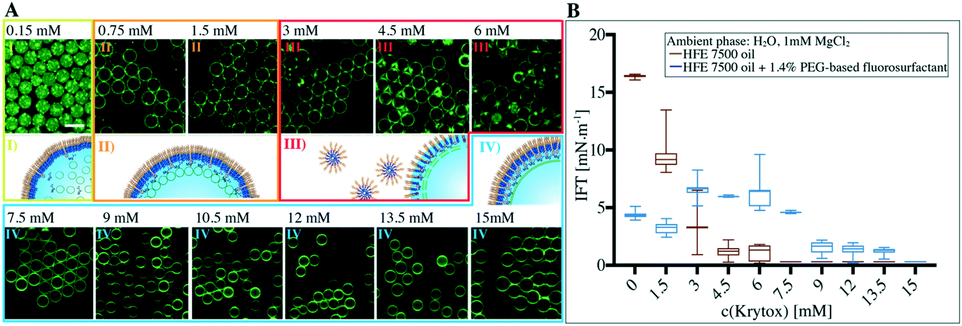 | ||
| Fig. 2 Effect of Krytox concentration on supported lipid bilayer formation within water-in-oil droplets. A) Representative confocal fluorescence images of lipid-containing microfluidic droplets at various Krytox concentrations from 0.15 mM to 15 mM. Green fluorescence from lipids (0.5% ATTO 488-labeled DOPE) encapsulated in the microfluidic droplets. Different Krytox concentrations, indicated on top of the fluorescence images, were mixed with 1.4 wt% PEG-based fluorosurfactant in the oil phase (HFE 7500 oil). Tris buffer supplemented with 10 mM Mg2+ and 26.5 μM SUVs (42.25% DOPC, 42.25% POPC, 15% cholesterol and 0.5% ATTO 488-labelled DOPE) was used as an aqueous phase for droplet formation. Certain Krytox-to-PEG-based fluorosurfactant ratios lead to I) multicompartment systems, II) multicompartment adhesion, III) flocculation or fusion of the droplets and IV) the formation of single compartments (dsGUVs). Scale bar, 50 μm. B) Effect of various Krytox-to-PEG-based fluorosurfactant ratios on the IFT as estimated by the pendant drop method. The increase in IFT of 1.4 wt% PEG-based fluorosurfactant plus Krytox concentrations ranging from 1.5 mM to 6 mM is connected to instability of droplets when using these mixtures for droplet production. | ||
Due to the nanoscale dimensions of the SUVs (68 nm in diameter according to DLS measurements, ESI,† Fig. S1), it is not possible to optically resolve whether a supported lipid bilayer has been formed or whether SUVs simply adhere to the surface. Therefore, we employed FRAP measurements to probe the bilayer formation (ESI,† Fig. S9 and Table S1). Depending on the Krytox concentration, we could group the measured diffusion coefficient values into two groups: 1.1 ± 0.1 μm2 s−1 for Krytox concentrations between 0.75 mM and 3 mM and 5 ± 0.4 μm2 s−1 for Krytox concentrations greater than 3 mM. We ascribe the lower diffusion coefficient to SUVs that are in active interaction with the droplet periphery and therefore exhibit slower diffusion.30 The higher diffusion coefficient, on the other hand, agrees well with literature values for the diffusion of lipids within a supported lipid bilayer.20,31 This indicates that the SUVs have ruptured and a supported lipid bilayer has been successfully formed. Additionally, SUV-containing droplets, stabilized by 1.4 wt% PEG-based surfactant and either 0 mM, 3 mM or 10.5 mM Krytox, were freeze-fractured and investigated by high-resolution cryo-SEM (ESI,† Fig. S10). Here, a homogeneous distribution of SUVs, SUV adhesion and lipid bilayer formation at the periphery could be observed in the presence of 0 mM, 3 mM or 10.5 mM Krytox, respectively. This supports the results obtained with confocal imaging and FRAP.
It is worth noting that some lipid leakage into the oil phase was observed in samples containing Krytox concentrations exceeding 12 mM. Furthermore, partial droplet flocculation (i.e., droplets adhering to each other without coalescing) occurred in samples with Krytox concentrations ranging from 3 mM to 6 mM. This might be due to micellar exclusion of the surfactants from the droplet interfaces as a result of interactions between Krytox and the PEG-based fluorosurfactants.32,33 Samples that exhibited flocculation ultimately showed droplet coalescence after a few days (ESI,† Fig. S11). Interfacial tension (IFT) measurements confirmed significant depletion of surfactants from the droplet interface at Krytox concentrations ranging from 3 mM to 6 mM (Fig. 2B). Interestingly, the depletion was observed when Krytox and PFPE–PEG-based surfactants were present in approximately equal molar ratios.
The effect of the lipid charge on compartment formation
The charge density in lipid vesicles was controlled through addition of negatively charged DOPG lipids (from 5% to 30%) to the neutral lipid composition used for SUV formation. Fig. 3 shows representative confocal fluorescence images of negatively charged SUVs encapsulated within the droplets stabilized by 1.4 wt% PEG-based fluorosurfactants and Krytox at different concentrations (from 0.15 mM to 12 mM). As expected, a greater amount of Krytox (3 mM) is needed to attract negatively charged SUVs to the droplet interface than that of neutral lipids added (0.75 mM). This is due to the fact that higher attraction forces are needed to overcome the repulsion between the negatively charged SUVs. Therefore, a higher density of Mg2+ ions is required on the inner droplet interface, which in turn corresponds to a higher Krytox concentration in the oil phase. | ||
| Fig. 3 Phase diagram of representative confocal images showing the effect of the lipid charge and Krytox concentration on the formation of a supported lipid bilayer within the microfluidic droplets. To evaluate the influence of negatively charged DOPG lipids on dsGUV formation, Tris buffer containing both 10 mM Mg2+ and SUVs with different lipid compositions (x% DOPC, x% POPC, 15% cholesterol, 5–30% DOPG, indicated on the left) was encapsulated in the droplets stabilized by surfactants which contained 1.4 wt% PEG-based fluorosurfactants and various Krytox concentrations as indicated above the fluorescence images. Certain Krytox-to-PEG-based fluorosurfactant ratios lead to I) multicompartment systems, II) multicompartment adhesion, III) flocculation or partial fusion of the droplets, or IV) the formation of a single compartment per droplet (dsGUV). Scale bar, 50 μm. | ||
FRAP measurements, performed on the lipids (30% DOPG) close to the droplet's periphery, revealed diffusion coefficients of 1 ± 0.1 and 4.2 ± 0.3 μm2 s−1 in the droplets stabilized by surfactants containing 1.5 and 10.5 mM Krytox, respectively (ESI,† Table S1). Just like in the case of the droplets containing neutral lipids, partial leakage of lipids into the oil phase was observed at Krytox concentrations above 12 mM (ESI,† Fig. S12), and droplet flocculation was observed at Krytox concentrations between 3 to 7.5 mM (Fig. 3). Note that reduced lipid leakage was detected when the lipids contained more than 20% DOPG (ESI,† Fig. S13). Additionally, droplet coalescence occurred when the encapsulated vesicles contained more than 15% DOPG lipids at Krytox concentrations between 3 mM and 7.5 mM.
GUV release from the polymer shell and oil phase into a physiological environment
The continuous lipid bilayer within the dsGUVs makes the release of the GUVs from the surfactant shell and oil phase into a physiological buffer possible.20 A bulk release approach (see the Materials and methods section), which allowed for the simultaneous generation of several hundred thousand free-standing GUVs within a few minutes, was employed to release assembled GUVs into the aqueous phase (Fig. 4). In this approach, the dsGUVs were collected in a microtube and supplemented with an osmolarity-matched aqueous release buffer. Subsequently, a de-emulsifier was added, which destabilized the droplet's surfactant shell and released GUVs into the aqueous phase. Note that no traces of oil or surfactant could be detected in the released GUVs by means of Raman spectrometry and fluctuation analysis as shown previously.20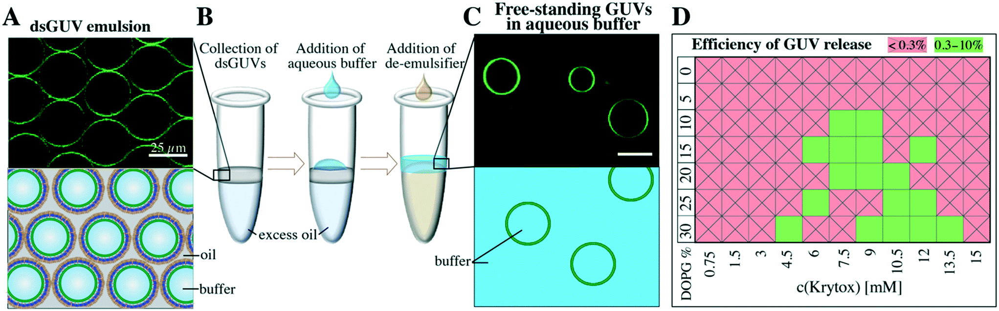 | ||
| Fig. 4 Bulk method to release free-standing GUVs from the stabilizing polymer shell and from the oil phase into the aqueous phase. A) Representative fluorescence image and sketch of dsGUVs (34.75% DOPC, 34.75% POPC, 15% cholesterol, 15% DOPG and 0.5% ATTO 488-labeled DOPE, 30 mM Tris, 10 mM Mg2+ ions) in the oil phase (containing 1.4 wt% PEG-based fluorosurfactant and 9 mM Krytox). B) For the release, droplets were collected inside a microtube and an osmolarity-matched buffer (30 mM Tris, 10 mM Mg2+ ions) was pipetted onto the droplet emulsion. Upon addition of a de-emulsifier (perfluoro-1-octanol), GUVs were released from the oil phase into the aqueous phase. C) A representative fluorescence image and sketch of free-standing GUVs after release. Scale bar: 25 μm. D) Efficiency of GUV (size 20–30 μm) release from dsGUVs depends on the Krytox concentration in the oil phase (HFE 7500 plus 1.4% PEG-based fluorosurfactants) and on the concentration of negatively charged lipids in the lipid composition. GUVs < 20 μm were not taken into account. | ||
Release efficiencies of up to 9% of the initial amount of produced dsGUVs were obtained. This is significant given the kHz production rates, i.e., 2.5 × 10⁶ dsGUVs are produced within 10 min and the overall yield can reach approximately 2.25 × 10⁵ GUVs. This efficiency makes our technology a high-precision and high-yield alternative to standard methods for GUV formation (for release efficiency calculations see the ESI,† Fig. S6). Not surprisingly, the release efficiency was affected by both Krytox concentration and lipid composition (Fig. 4D). Large amounts of GUVs were released from the dsGUVs containing more than 10% negatively charged lipids. However, efficient release was only achieved at Krytox concentrations between 6 mM to 13.5 mM. Higher Krytox concentrations were necessary when GUVs contained more negatively charged lipids. As expected, release was not achieved from droplets stabilized by a surfactant solution containing less than 3 mM Krytox, because no continuous supported lipid bilayer could form under these conditions. Unfortunately, the release of GUVs consisting of neutral lipids was significantly lower (below 0.3%). This might be attributed to the fact that a partial leakage of lipids into the oil phase was observed predominantly in the case of neutral lipids (ESI,† Fig. S13). However, the leakage and release efficiency of neutral GUVs could be improved by replacing the 10 mM MgCl2 with 50 mM KCl.
It is worth mentioning that during this bulk release, destabilized droplets might split or fuse with adjacent droplets leading to a non-homogeneous size distribution of the released GUVs (ESI,† Fig. S14). Future optimization of the release process might improve the efficiency and size distribution range of released GUVs. When a homogeneous size distribution is required, GUVs should be released using a microfluidic device as shown previously.20
The multicompartment systems described above (Fig. 1A) are solely confined by the droplet polymer shell; thus, their observation and analysis are performed directly in the oil/surfactant environment. To transfer a multicompartment system into a physiological environment, the aqueous volume needs to be enclosed by an additional outer lipid bilayer. To obtain this, we encapsulated a SUV-based multicompartment system inside a dsGUV using experimental conditions similar to those for single-compartment dsGUV formation (Fig. 5). However, an excess amount of encapsulated SUVs (greater than that required for just the formation of a continuous bilayer) was necessary to obtain free-floating SUVs within the volume of a dsGUV. Importantly, no accumulation of lipids on the periphery was observed during the time-lapse microscopy analysis (2 h) of the multicompartment systems. This indicates that the internal SUVs remain stable within the GUV lumen. A multilamellar GUV should feature higher fluorescence intensity on its periphery. The fact that the fluorescence intensity profile of the released multicompartment GUV agrees well with our single GUVs is a strong indication of its unilamellarity (ESI,† Fig. S15).
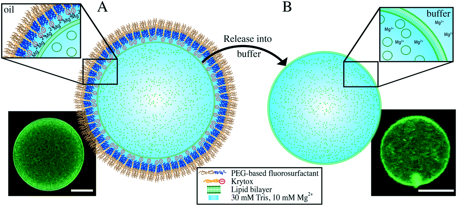 | ||
| Fig. 5 Schematic representation and confocal fluorescence images of multicompartment systems enclosed by a dsGUV or a free-standing GUV. Lipid composition: 27.25% DOPC, 27.25% POPC, 30% DOPG, 15% cholesterol, 0.5% ATTO 488-DOPE in Tris buffer, 10 mM Mg2+. A) Excess SUVs (53 μM) were encapsulated in a water-in-oil droplet stabilized by PEG-based fluorosurfactants with 9 mM Krytox. This led to the formation of a lipid bilayer inside the surfactant shell. Excess SUVs remained in the droplet volume, resulting in a multicompartment dsGUV. The lower inset shows a representative confocal fluorescence image of green fluorescence emitted by labeled lipids. B) Released GUV-enclosed multicompartment system in an osmolarity-matched aqueous buffer. The lower inset shows a representative confocal fluorescence image of green fluorescence emitted by labeled lipids. Scale bar: 10 μm. | ||
Summary and conclusions
In this work we present a practical and highly-tunable method to produce two key types of protocell model systems: cell-sized multicompartment systems and single compartments. Both of these protocell systems existed in a surfactant-stabilized water-in-oil droplet as well as in a physiological aqueous environment after releasing GUVs out of the surfactant shell and oil phase into water-based buffers. On-demand production of a choice of either protocell system is achieved by tuning the ratio between uncharged and negatively charged commercially available surfactants. We first generate a multicompartment system in which a large number of SUVs are homogeneously distributed within a water-in-oil droplet. The droplet is stabilized by inert and uncharged PEG-based fluorosurfactants. By providing a negatively charged inner droplet interface, adsorption of the SUVs and subsequent formation of a spherical supported lipid bilayer, a so-called dsGUV is obtained. To better understand the concurrent roles of both the lipid and surfactant charge, we systematically analyzed the transition from multicompartment systems to dsGUVs as a function of these two parameters. Finally, we demonstrate the successful release of free-standing GUVs from the surfactant shell and the oil phase into physiological conditions. Remarkably, we show that multicompartment systems can also be enclosed within a GUV, mimicking the architecture of eukaryotic cells.To conclude, we demonstrate a practical technique to tailor the interface of surfactant-stabilized water-in-oil droplets for the formation of either a multicompartment or a single compartment system with the possibility of releasing free-standing GUVs into a physiological environment. The method is versatile and can be adapted for different buffer conditions, lipid compositions, and encapsulated biomolecules. It also presents the limit for the formation of dsGUVs by this technology. For this, it is essential to adjust the ionic conditions or Krytox concentration as demonstrated for the broad parameter space we explored. The developed multicompartment system may provide a spatially confined reaction space for the observation and analysis of SUV-based functional modules. Additionally, this multicompartment system may mimic the crowded environment inside a living cell, in which membrane-enclosed compartments make up nearly half of the cell volume.1 dsGUVs, on the other hand, due to the fact that they are highly stable as single compartment systems, offer the unique possibility of sequential loading with various biomolecules by means of a high-throughput microfluidic picoinjection technology.20 Furthermore, their high-throughput production and subsequent release of the assembled GUVs into a physiological buffer make this approach an efficient alternative to standard GUV formation methods. This work will contribute to increasing the availability of versatile and complex lipid-based compartments for applications ranging from synthetic cellular systems to drug delivery and catalysis through providing a simple, yet high-throughput method for their production.
Author contributions
B. H., I. P. and J. P. S. conceived the research. B. H. performed most of the experiments. K. G. performed and analyzed the lipid leakage experiments and partially contributed to the ion-concentration and FRAP experiments and analysis. M. S. and J.-W. J. performed and analyzed the MS and FTIR experiments, respectively. I. P. and J. P. S. supervised the research. The manuscript was written by all authors through their contributions, and the final version of the manuscript was approved by all authors.Conflicts of interest
All authors have no conflicts to declare.Acknowledgements
Parts of this research leading to these results have received funding from the European Research Council/ERC Grant Agreement no. 294852, SynAd. This work is also part of the MaxSynBio consortium, which is jointly funded by the Federal Ministry of Education and Research of Germany and the Max Planck Society. This work was also partly supported by the SFB 1129 of the German Science Foundation and the VolkswagenStiftung (priority call ‘Life?’). J. P. S. is the Weston Visiting Professor at the Weizmann Institute of Science and part of the excellence cluster CellNetworks at the University of Heidelberg. I. P. acknowledges the support of the Alexander von Humboldt Foundation. K. G. received funding from the European Union's Horizon 2020 Research and Innovation Program under the Marie Skłodowska-Curie grant agreement No. 792270. The support of Jennifer Young and Christoph Frey for editing the manuscript is highly acknowledged. The Max Planck Society is appreciated for its general support in all aspects of our research. Open Access funding provided by the Max Planck SocietyReferences
- B. Alberts, A. Johnson, J. Lewis, M. Raff, K. Roberts, P. Walter, B. Alberts, A. Johnson, J. Lewis, M. Raff, K. Roberts and P. Walter, Molecular biology of the cell, 5th edn, Garland Science, 2008 Search PubMed.
- J. W. Szostak, D. P. Bartel and P. L. Luisi, Nature, 2001, 409, 387–390 CrossRef PubMed.
- S. M. Nomura, K. Tsumoto, T. Hamada, K. Akiyoshi, Y. Nakatani and K. Yoshikawa, ChemBioChem, 2003, 4, 1172–1175 CrossRef PubMed.
- H. Terasawa, K. Nishimura, H. Suzuki, T. Matsuura and T. Yomo, Proc. Natl. Acad. Sci. U. S. A., 2012, 109, 5942–5947 CrossRef PubMed.
- L. Rodriguez-Arco, M. Li and S. Mann, Nat. Mater., 2017, 16, 857–863 CrossRef PubMed.
- D. van Swaay, T. Y. D. Tang, S. Mann and A. de Mello, Angew. Chem., Int. Ed., 2015, 54, 8398–8401 CrossRef PubMed.
- X. M. Liu, P. Zhou, Y. D. Huang, M. Li, X. Huang and S. Mann, Angew. Chem., Int. Ed., 2016, 55, 7095–7100 CrossRef PubMed.
- M. Ugrinic, A. Zambrano, S. Berger, S. Mann, T. Y. D. Tang and A. Demello, Chem. Commun., 2018, 54, 287–290 RSC.
- B. M. Discher, Y. Y. Won, D. S. Ege, J. C. M. Lee, F. S. Bates, D. E. Discher and D. A. Hammer, Science, 1999, 284, 1143–1146 CrossRef PubMed.
- C. G. Palivan, R. Goers, A. Najer, X. Y. Zhang, A. Car and W. Meier, Chem. Soc. Rev., 2016, 45, 377–411 RSC.
- M. P. N. Juniper, M. Weiss, I. Platzman, J. P. Spatz and T. Surrey, Soft Matter, 2018, 14, 901–909 RSC.
- N. Ichihashi and T. Yomo, Curr. Opin. Chem. Biol., 2014, 22, 12–17 CrossRef PubMed.
- M. I. Angelova and D. S. Dimitrov, Faraday Discuss. Chem. Soc., 1986, 81, 303–311 RSC.
- J. P. Reeves and R. M. Dowben, J. Cell. Physiol., 1969, 73, 49–60 CrossRef PubMed.
- S. Matosevic, BioEssays, 2012, 34, 992–1001 CrossRef PubMed.
- H. Stein, S. Spindler, N. Bonakdar, C. Wang and V. Sandoghdar, Front. Physiol., 2017, 8, 16 Search PubMed.
- J.-P. Colletier, B. Chaize, M. Winterhalter and D. Fournier, BMC Biotechnol., 2002, 2, 9 CrossRef PubMed.
- J. C. Stachowiak, D. L. Richmond, T. H. Li, A. P. Liu, S. H. Parekh and D. A. Fletcher, Proc. Natl. Acad. Sci. U. S. A., 2008, 105, 4697–4702 CrossRef PubMed.
- Y. Elani, R. V. Law and O. Ces, Nat. Commun., 2014, 5, 5 Search PubMed.
- M. Weiss, J. P. Frohnmayer, L. T. Benk, B. Haller, J. W. Janiesch, T. Heitkamp, M. Borsch, R. B. Lira, R. Dimova, R. Lipowsky, E. Bodenschatz, J. C. Baret, T. Vidakovic-Koch, K. Sundmacher, I. Platzman and J. P. Spatz, Nat. Mater., 2018, 17, 89–96 CrossRef PubMed.
- Y. Elani, Biochem. Soc. Trans., 2016, 44, 723–730 CrossRef PubMed.
- N.-N. Deng, M. Yelleswarapu and W. T. S. Huck, J. Am. Chem. Soc., 2016, 138, 7584–7591 CrossRef PubMed.
- K. Göpfrich, I. Platzman and J. P. Spatz, Trends Biotechnol., 2018 DOI:10.1016/j.tibtech.2018.03.008.
- A. R. Abate, T. Hung, P. Mary, J. J. Agresti and D. A. Weitz, Proc. Natl. Acad. Sci. U. S. A., 2010, 107, 19163–19166 CrossRef PubMed.
- M. Tanaka and E. Sackmann, Nature, 2005, 437, 656–663 CrossRef PubMed.
- Y. Xia and G. M. Whitesides, Annu. Rev. Mater. Sci., 1998, 28, 153–184 CrossRef.
- I. Platzman, J.-W. Janiesch and J. P. Spatz, J. Am. Chem. Soc., 2013, 135, 3339–3342 CrossRef PubMed.
- B. Riechers, F. Maes, E. Akoury, B. Semin, P. Gruner and J. C. Baret, Proc. Natl. Acad. Sci. U. S. A., 2016, 113, 11465–11470 CrossRef PubMed.
- L. S. Roach, H. Song and R. F. Ismagilov, Anal. Chem., 2005, 77, 785–796 CrossRef PubMed.
- M. Kyoung and E. D. Sheets, Biophys. J., 2008, 95, 5789–5797 CrossRef PubMed.
- R. Machan and M. Hof, Biochim. Biophys. Acta, 2010, 1798, 1377–1391 CrossRef PubMed.
- H. Katepalli, A. Bose, T. A. Hatton and D. Blankschtein, Langmuir, 2016, 32, 10694–10698 CrossRef PubMed.
- M. P. Aronson, Langmuir, 1989, 5, 494–501 CrossRef.
Footnote |
| † Electronic supplementary information (ESI) available. See DOI: 10.1039/c8lc00582f |
| This journal is © The Royal Society of Chemistry 2018 |