
 Open Access Article
 This Open Access Article is licensed under a
 Creative Commons Attribution 3.0 Unported Licence
Droplet microfluidics for the construction of compartmentalised model membranes
T.
Trantidou†
 a,
M. S.
Friddin†
a,
A.
Salehi-Reyhani†
abc,
O.
Ces
*abc and
Y.
Elani
*abc
a,
M. S.
Friddin†
a,
A.
Salehi-Reyhani†
abc,
O.
Ces
*abc and
Y.
Elani
*abc
aDepartment of Chemistry, Imperial College London, London, SW7 2AZ, UK. E-mail: o.ces@imperial.ac.uk; yuval.elani10@imperial.ac.uk
bInstitute of Chemical Biology, Imperial College London, London, SW7 2AZ, UK
cfabriCELL, Imperial College London, SW7 2AZ, UK
First published on 1st August 2018
Abstract
The design of membrane-based constructs with multiple compartments is of increasing importance given their potential applications as microreactors, as artificial cells in synthetic-biology, as simplified cell models, and as drug delivery vehicles. The emergence of droplet microfluidics as a tool for their construction has allowed rapid scale-up in generation throughput, scale-down of size, and control over gross membrane architecture. This is true on several levels: size, level of compartmentalisation and connectivity of compartments can all be programmed to various degrees. This tutorial review explains and explores the reasons behind this. We discuss microfluidic strategies for the generation of a family of compartmentalised systems that have lipid membranes as the basic structural motifs, where droplets are either the fundamental building blocks, or are precursors to the membrane-bound compartments. We examine the key properties associated with these systems (including stability, yield, encapsulation efficiency), discuss relevant device fabrication technologies, and outline the technical challenges. In doing so, we critically review the state-of-play in this rapidly advancing field.
 Tatiana Trantidou | Tatiana Trantidou received her PhD (2014) in biomedical electronics from Imperial College London, UK. From 2014–2015 she worked as a post-doctoral research scientist at the Southampton Nanofabrication Centre (UK) on the development of novel digital manufacturing technologies for biomedical applications. Since 2015, she is a Research Fellow at the Department of Chemistry developing technological platforms to scale up the production of smart therapeutics. Her research interests are on conventional and unconventional micro/nanofabrication technologies for tissue engineering and for micro/nanofluidics for synthetic biology. She is author of 15 journal papers, 1 patent and 12 conference papers. |
 Mark Friddin | Mark Friddin received his PhD in Electrical Engineering from the University of Southampton (2014), was awarded a Master of Engineering in micro- and nano-technology from the University of Liverpool (2009) and has a Bachelors degree in Biochemistry from the University of Nottingham (2008). His expertise is in the assembly, functionalisation and electrical characterisation of model membranes formed between aqueous microdroplets in oil. Since joining the Chemistry Department at Imperial College in 2015 his research has mainly focused on the development of new micro- and opto-fluidic platform technologies for constructing model membranes, particularly using rapid prototyping. |
 Ali Salehi-Reyhani | Dr. Ali Salehi-Reyhani is an EPSRC-UKRI Innovation Fellow at Imperial College London where he leads the Systems and Synthetic Biology group, conducting multidisciplinary research and leveraging translational activity to drive impacts on healthcare. He pioneered single molecule microfluidic platforms for single cell analysis supporting over £10m in research funding. His microfluidic expertise is also helping to miniaturise high-performance liquid chromatography for point-of-care, has founded several spinouts and sits on scientific advisory boards for MedTech start-ups. His interest in bottom-up synthetic biology lies in the opportunity to create simplified cell mimetics to understand the underlying mechanisms of cell function. |
 Oscar Ces | Oscar Ces is a Professor of Chemical Biology at the Department of Chemistry at Imperial College London and a Fellow of the Royal Society of Chemistry. He is currently Director of the Institute of Chemical Biology (ICB), the EPSRC ICB Centre for Doctoral Training, the Leverhulme Doctoral Training Centre for Cellular Bionics and Co-Director of both fabriCELL and the Imperial College Advanced Hackspace. His research is focussed on biomembrane engineering, drug-membrane interactions, biomimicry, soft condensed matter, chemical biology, microfluidics, artificial cells, single cell analysis and lipid membrane mechanics. |
 Yuval Elani | Yuval is an EPSRC Research Fellow at Imperial College. His group works in the areas of Soft Microsystems Engineering and Chemical Synthetic Biology. He received multidisciplinary training at Cambridge and Imperial, and has expertise in soft-matter, microfluidics, optofluidics, chemical biology, and biophysics. He is particularly interested in exploring biointerfaces between living and synthetic cells and in optical manipulation techniques for synthetic biology. Yuval's work has been recognised through awards from the Royal Society of Chemistry, World Economic Forum, and the Parliamentary and Scientific Committee. He co-founded the fabriCELL centre for artificial cell research and the Cellular Bionics Doctoral Training Centre. |
1. Introduction
Membranes comprised of phospholipid bilayers are essential to the function of all living cells. They serve as a critical barrier between the cell and its environment, and are necessary for intracellular structure and communication. Bilayer membranes provide mechanical supports for anchoring the molecular machinery required to regulate the exchange of metabolic components and chemical signals between the cell interior and exterior, and can act as 2D surfaces which biochemical reactions take place on.1 Membranes are known to be highly dynamic fluid surfaces, serving a multitude of purposes and have been the focus of intensive research for many decades.2Such features have long motivated interest in studying the biophysical properties of lipid bilayers and membrane proteins using model architectures engineered from user-defined mixtures of phospholipids and cell extracts. For decades, lipid bilayer constructs have been formed as bilayer encapsulated fluid spheres (lipid vesicles/liposomes), black lipid membranes (BLMs) and supported lipid bilayers (SLBs),2–4 although new classes of multi-compartment structures are increasingly being developed.
The broad adoption of these biomimetic model architectures has led to success in studying reconstituted membrane proteins,2 bilayer phase behaviour,5,6 and the lateral organisation of membranes.7 Such achievements have motivated recent interest in developing approaches beyond simply assembling single membranes, and towards engineering spatially organised multi-compartment architectures that more closely resemble biological cells. In this sense, spatially distinct, inter-communicating compartments are likely to be vital for providing the complexity necessary to serve higher-order functions. This is best evident in cells where various biological functions are performed using membranes – trafficking of material within and between organelles as well as extracellular signalling and exchange of cargo are all enabled by membranes and compartmentalisation across a broad range of length-scales. These processes emphasise the degree of organisation required on the microscale and how this, in turn, supports the emergence of the collective ordering of cells on the macroscale.
The advantages of compartmentalisation arise from the spatial organisation of chemical species in space. This enables the establishment of concentration gradients, maintenance of non-equilibrium states, isolation of otherwise interfering processes, and the existence of spatially distinct microenvironments chemically optimised for defined purposes. These features are utilised by cells, but can also be taken advantage of in the construction of artificial membrane-bound microsystems. Multi-compartment architectures have potential as microreactor chassis,8,9 where individual steps of multi-step reactions occur in isolated compartments with different chemical conditions (different pH, redox states, solvents, buffers etc.). Compartmentalisation aids the development of responsive systems, where membranes can be broken down selectively in response to defined stimuli, for example, to initiate chemical reactions in response to stimuli such as heat, pH or light.10–13 Multi-compartment constructs, therefore, hold promise in therapeutic delivery for example, for in situ drug synthesis, multi-stage drug release and for multi-modal systems. Recently, a new concept in compartmentalisation was explored, where whole cells were embedded within vesicle-based synthetic cells. The encapsulated cells could act as living sub-compartments, and engineered, for example, to perform a bioreactor14 or biosensor155 function inside the larger hybrid assembly. Finally, the very process of mimicking cellular compartmentalisation in a biomimetic environment is valuable for the study of biological process in a simplified, well-controlled, and easily manipulated environment.15
In response to the above, new generations of multi-compartment model architectures have begun to emerge. These include multi-compartment vesicles, vesosomes (nested vesicles) and lipid-stabilised water-in-oil-in-water (w/o/w) double emulsions (multisomes). Despite having an intermediate oil layer, the latter still have a lipid membrane delineate all aqueous volumes from one another. Finally, droplet interface bilayers (DIBs)16 are lipid monolayer coated w/o droplets, which can be manipulated into contact to form large-scale networked assemblies existing in a bulk oil environment. These structures are illustrated in Fig. 1A.
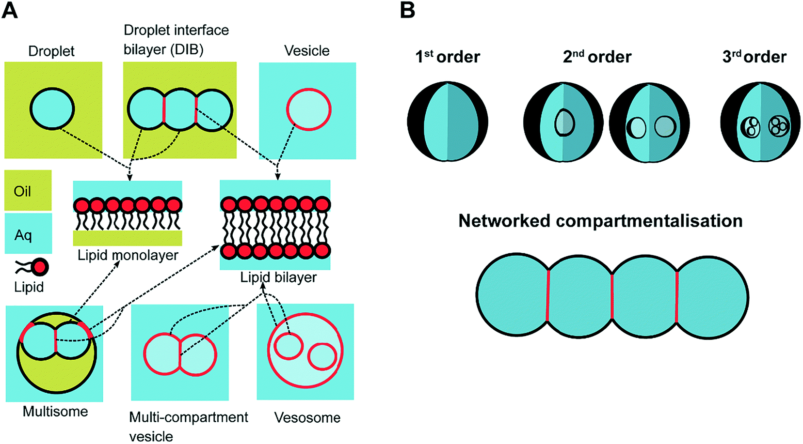 | ||
| Fig. 1 Multi-compartment architectures and different orders of compartmentalisation. (A) Compartmentalised bilayer architectures made from lipid monolayer coated droplets in oil and lipid bilayer coated droplets in water. These subunits are used to assemble networks of DIBs, multisomes, multi-compartment vesicles and vesosomes. The presence of a lipid monolayer or a lipid bilayer within these structures is highlighted in black and red respectively using the arrows. (B) Schematic showing different levels of compartmentalisation, including networked compartmentalisation, where compartments are arranged side-by-side. Compartments are delineated from one another by a lipid bilayer when an aqueous phase is present on either side, or by a lipid monolayer when there is an oil/water interface present. The different shades of blue are used to signify that the solution on either side of the membrane are of the same phase (aqueous) but could have different compositions. | ||
These bilayer constructs offer exciting possibilities for bottom-up synthetic biologists. However precise control over architecture, compartment number, size and connectivity, and the content of the membrane and encapsulated cargo cannot be effectively achieved using traditional methods such as electroformation, film hydration, or extrusion.17–19 Although a degree of control can be achieved using one-by-one manual manipulation methods (for example pipetting or micromanipulation using electrodes), this drastically increases the sizes to those that have cellular relevance, since generation and manipulation of these compartments is limited from a few hundreds of micrometres (in diameter) to a couple of millimetres. Generation throughput is drastically reduced, prohibiting the production of large-scale tissue-like networks.
The need for precise, high-throughput and highly controlled fluid handling makes microfluidic approaches well placed to meet the technical demands of compartmentalisation. Droplet microfluidics is most relevant, as droplets are either the fundamental building blocks themselves, or serve as template precursors for the membrane-bound compartments. The control offered by microfluidics is critical in enabling the construction of model systems with higher degrees of compartmentalisation: beyond first generation single containers and second generation embedded compartments, to third order structures and beyond,20 as illustrated in Fig. 1B.
In this tutorial review, we focus on the use of droplet microfluidics to generate compartmentalised model membrane architectures. We provide an outline of the underlining concepts regarding the fluid dynamics of these devices and review microfluidic platforms for engineering DIBs, DIB networks, multisomes, polymersomes, multi-compartment vesicles and vesosomes. We assess the performance of these platforms against conventional methods by evaluating their throughput, efficiency and yield in producing compartmentalised membranes. We discuss relevant device fabrication technologies and explore the challenges that lie ahead in order to realise future applications for compartmentalised systems.
2. Key concepts in droplet microfluidics for assembling model architectures
2.1 Dimensionless descriptors of the system
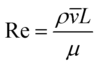
The behaviour of fluids within microfluidic channels may be broadly described by ratios of specific physical properties or forces that define a set of dimensionless numbers (Table 1). For multiphase flow, interfacial forces which act at fluid–fluid and fluid–wall interfaces are important. In addition, flow is governed by relative contributions from inertia, viscous forces and gravity.| Parameter | Symbol | Formula | Definitions |
|---|---|---|---|
| Reynolds number | Re |
|
ρ = fluid density ![[small nu, Greek, macron]](https://www.rsc.org/images/entities/i_char_e0ce.gif) = fluid velocity L = characteristic length μ = dynamic viscosity Δρ = difference in density between 2 fluids g = gravity acceleration σ = interfacial tension μd = viscosity of dispersed phase μc = viscosity of continuous phase = fluid velocity L = characteristic length μ = dynamic viscosity Δρ = difference in density between 2 fluids g = gravity acceleration σ = interfacial tension μd = viscosity of dispersed phase μc = viscosity of continuous phase |
| Bond number | Bo |
|
|
| Weber number | We |
|
|
| Capillary number | Ca |
|
|
| Viscosity ratio | λ |
|
|
| Coefficient of variation | CV |
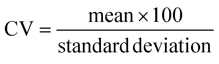
|
Fluid flow within microfluidic channels is often characterised by the Reynolds number (Re),21 a ratio of inertial to viscous forces. Consequently, it quantifies the relative contribution of each force for given flow conditions. Generally, flow is described to be either laminar (low Re < 1) or turbulent (high Re > 1000). Turbulent flow is dominated by inertial forces, producing random eddies, vortices and other chaotic fluctuations. As a result of turbulent mixing, concentration gradients are significantly enhanced and timescales for mixing are low. Due to the typical flow rates and characteristic length scales of channels, microfluidic flow is generally laminar. Mixing in microfluidic systems is dominated by diffusion, an important consideration when performing chemical reactions at these length-scales. The Reynolds number is more often useful when considering the flow and transport of droplets rather than their generation.
While bulk flows are typically laminar in these systems, the fluid dynamics become more complicated at the point of droplet generation. To generate a droplet, two immiscible fluids must form an interface that undergoes significant deformation followed by spontaneous fragmentation into discrete droplets. While the Reynolds number well characterises the dynamics of monophasic flow in a microfluidic channel, it is not commonly used to describe droplet generators.
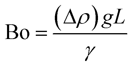
The difference in mass density between two fluids and the importance of interfacial forces with respect to gravity is given by the Bond number (Bo), or sometimes the Eötvös number (Eo).22 In most microfluidic applications Bo ≪ 1, meaning that interfacial forces dominate and the effect of gravity can be disregarded. Control over droplet size and their generation rate can be adjusted by controlling the Bond number.
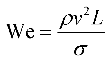
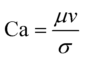
The rate of multiphase flow through the microchannels will dictate the mechanism of droplet formation. The Weber number (We) is the ratio of inertia to interfacial tension.23 Fluid inertia is negligible for bulk fluid flow in microfluidic channels (We < 1); however, it becomes significant in the cases of high velocity jets or in the vicinity of droplet formation, as they pinch off from the continuous phase fluid. Perhaps the most critical parameter for applications discussed here is the capillary number (Ca),24 representing the relative effect of viscous forces over surface tension across an interface. The capillary number typically ranges from 10−3 to 10 and helps describe the size and shape of resulting droplets. Spherical droplets are produced as a result of a low Ca whereby the interfacial surface area is minimised due to interfacial tension dominating. A high Ca indicates that viscous forces are instead dominant and results in asymmetric morphologies.
2.2 Droplet generation
Droplet formation can be achieved through a variety of emulsification methods. Conventional bulk techniques offer little control over droplet production, leading to variability in size and monodispersity. In contrast, the precision and control of microfluidic fabrication and fluid flows within microchannels has enabled unprecedented control of droplet size, allowing droplets to be either monodisperse or of a desired polydispersity.Droplet formation may be active or passive, with the majority of techniques falling into the latter category. Passive devices use the microchannel geometry to generate droplets in a continuous format. Active methods incorporate electrodes, centrifugation, piezo-actuators, or exploit laser-based techniques to induce interfacial deformations and instabilities that result in droplet formation.25
There have emerged three broad types of microfluidic droplet generation geometries – cross-flow, co-flow and flow-focusing (Fig. 2A). Due to its simplicity, the most common geometry is the T-junction, which forms the basis of other cross-flow geometries. A T-junction is formed at the intersection of two orthogonal inlets carrying two immiscible phases, one continuous phase for the carrier fluid and one dispersed phase which breaks up into droplets. In the vicinity of where they are produced, the dispersed phase can be described to break up by squeezing, dripping or jetting (Fig. 2B). Dripping and jetting23 both arise from capillary instability as interfacial tension forces tend to minimise the interfacial area according to the thermodynamic principle of minimum interfacial energy. The competition of viscous, inertial and interfacial tension forces determines the specific breakup mode of droplet generation.25 On the contrary, the squeezing regime26 is the result of a different mechanism, where channel confinement plays a dominant role and inhibits capillary instability. In this case, droplet breakup exhibits quasi-static mechanisms until the thread pinches off.
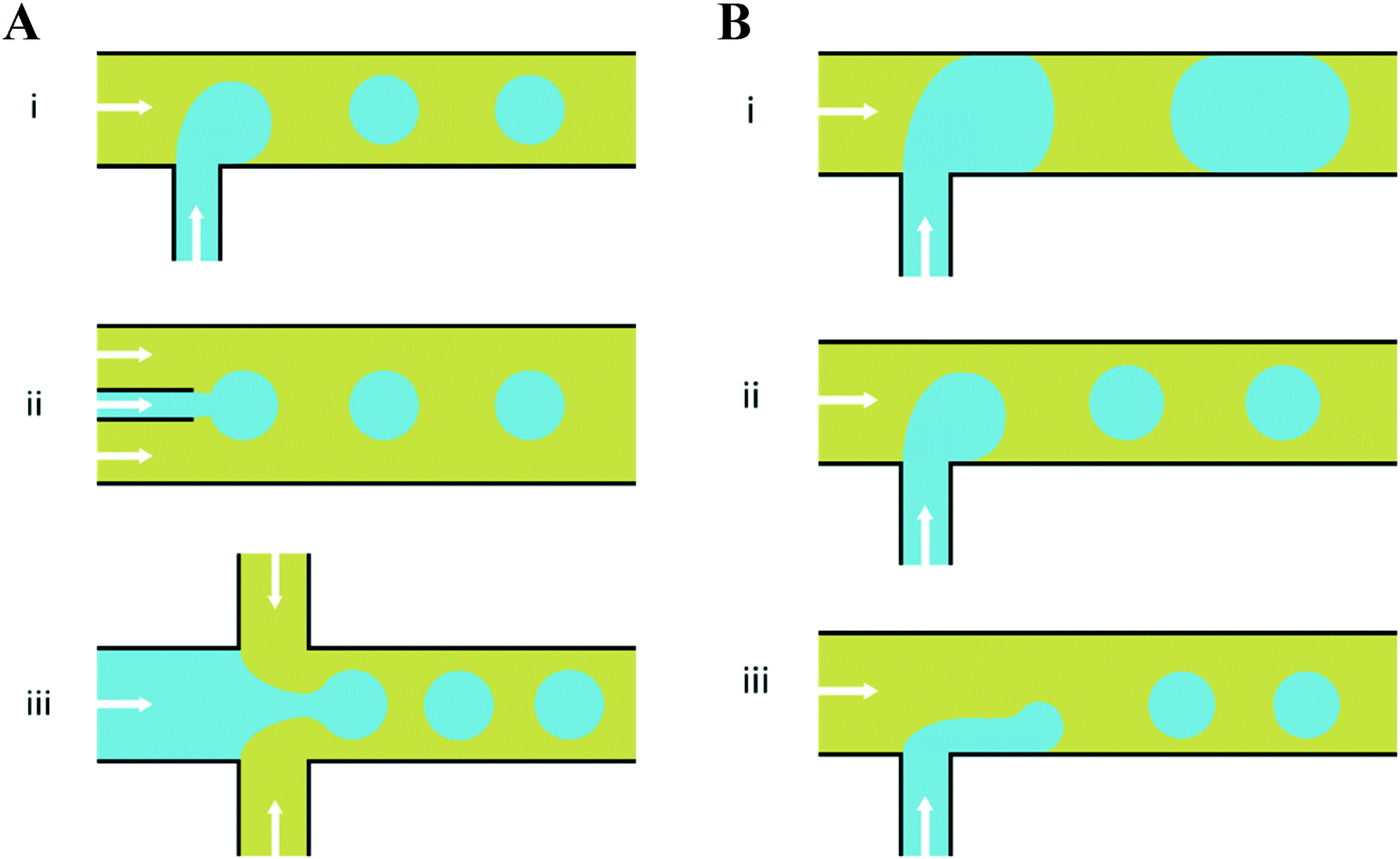 | ||
| Fig. 2 Planar devices for droplet generation. (A) Microfluidic droplet generation geometries of (i) cross-flow, (ii) co-flow and (iii) flow-focusing. (B) Different modes of droplet break up in a microfluidic T-junction; (i) squeezing – droplets break up predominantly due to channel confinement at the microfluidic junction, yielding a ‘slug-like’ appearance (ii) dripping – as capillary number increases, viscous forces dominate over interfacial tension effects and droplet breakup occurs right at the dispersed nozzle and (iii) jetting – by increasing the continuous-fluid or dispersed-fluid flow rate, an extended liquid jet ultimately breaks up into droplets at the end of the jet. The arrows indicate the overall direction of bulk fluid flow and the blue and yellow colours indicate the dispersed and continuous phases, respectively. | ||
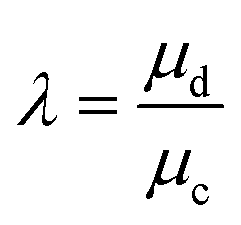
The resultant size of a droplet produced by a T-junction geometry is influenced by a number of parameters including; i) the ratios of width and height of the side to main channels, ii) the ratio of flow rates of the continuous and dispersed phases feeding the junction, iii) the capillary and Reynolds numbers, and iv) the ratios of viscosity and density of the two phases. Several reports have focussed on the systematic investigation of droplet size and shape dependence on these parameters,27 however, altering these parameters in isolation is difficult to achieve experimentally, which has led to efforts in producing numerical simulations.28–31 The simplest model suggested by Thorsen et al., was based on the shear forces between phases upon meeting at the T-junction. Thus, the size of droplets formed could be estimated within a factor of 2 by 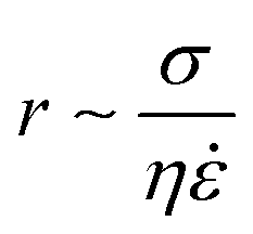 , where r is the droplet radius, σ is the interfacial tension between the phases, η is the viscosity of the continuous phase and ε is the shear rate.32 A statistical analysis of literature data by Steegmans et al. has helped generalise the rules of behaviour and provide design guidelines for T-junctions.33 They considered droplets to form in two stages when influenced by shear; a droplet first grows and then detaches. Droplet size can then be controlled by controlling growth time, altering channel dimensions or detachment time, and also by altering the ratio of the flow rates. The viscosity ratio (λ) of the phases can affect the growth time and thereby result in larger droplets. An increase in capillary number will lead to droplet sizes decreasing. This effect becomes stronger the lower the viscosity ratio (λ < 1).34
2.3 Multiphase device geometry
The formation of a single droplet is an important step in the assembly of compartmentalised and multiphase arrangements. More complex droplet structures may be formed from the basic single emulsion droplet. Such structures may be formed either as higher order emulsions, whereby multiple concentric immiscible shells are formed surrounding a central core, or by containing droplets within droplets, and variants thereof (Fig. 1B). Double emulsions may be generated by repeating the first emulsification step and have been demonstrated in serial T-junctions,35,36 serial flow focusing junctions (FFJ),37,38 consecutive flow-focusing generators,39 and combinations such as a flow-focusing arrangement whereby the inner phase was formed at a co-flow focussing geometry.40The wettability of the channels in segmented flow planar microfluidics must be such that it favours the carrier phase over the dispersed phase, at and downstream of the focussing junction. When different phases constitute the carrier phase as different regions of the device (e.g. when forming w/o/w double emulsions) then the wettability of the device needs to be different accordingly. For this reason, chemical modifications to the surfaces must be made to favour droplet formation.41 Water-in-oil (w/o) droplets are only formed at a hydrophobic microfluidic junction, whereas oil-in-water (o/w) droplets are generated at a hydrophilic junction. The processes to achieve this become challenging when forming multiple emulsions owing to the requirement of surface hydrophobicity or hydrophilicity to switch or even alternate over length scales on the order of microns.42,43
Compared to surfactant-stabilised droplet generation, the microfluidic formation of lipid-stabilised droplets is more challenging. Favourable wettability conditions between lipids and the channel materials are challenging to achieve, and many surface modification techniques are incompatible with lipids. The use of surfactants to dynamically modify the microchannel surface has also been demonstrated but this poses another set of difficulties,44 since surfactants may interfere with the lipid membranes themselves. Other modification strategies, commonly used for poly(dimethyl)siloxane (PDMS)-based microfluidic devices, involve plasma oxidation followed by deposition of hydrophilic molecules, such as polyvinyl alcohol (PVA)45,46 and charged polyanions and polycations.47,48
The issue of controlling surface wettability and the necessary schemes to seal such modified devices49,50 has led to the development of non-planar geometries and devices which incorporate capillaries (Fig. 3). Non-planar geometries are formed in 3D microfluidic devices wherein the cross-sectional area of the droplet forming junction is smaller than that of the channels immediately downstream (Fig. 3A); this allows the carrier phase to fully envelop the dispersed phase, helping to de-wet it from the channel walls.51 Devices which incorporate capillaries are able to achieve this too.52–54 Individually, the surface chemistry of each capillary may be readily modified prior to incorporation into a multi-capillary device. The arrangement of concentric, coaxial and multi-bore capillaries can be difficult to achieve; however, the generation of higher order emulsions is made more tractable with such devices (Fig. 3B).55–57
 | ||
| Fig. 3 Non-planar devices. (A) These can be used to overcome the difficulty in modifying the hydrophilicity/hydrophobicity of surfaces in facilitating droplet generation, a non-planar 3D channel geometry may be used which forms droplets by ‘wrapping’ them with the continuous phase at the junction. Such geometries are capable of producing droplets even with unfavourable surface wetting properties. Figure reproduced from ref. 51 with permission from Royal Society of Chemistry. (B) Despite difficulties in assembly, it is generally straightforward to produce higher order architectures using device which incorporate co-axially aligned glass capillaries. Shown is a (i) schematic and (ii) optical microscopy image of a microfluidic capillary device capable of generating (iii) monodisperse double emulsions with two different inner droplets containing dye. Figure reproduced from ref. 57 with permission from Royal Society of Chemistry. | ||
3. Membrane architectures
3.1 Vesicles
Although this review focuses specifically on multi-compartment membrane architectures, it is relevant to briefly discuss droplet microfluidic techniques for generation of the uni-compartment lipid vesicles, as these often serve as the building blocks for their higher-order counterparts. Vesicles formed by droplet microfluidics have tended to be 1–100 μm in diameter (Giant Unilamellar Vesicles; GUVs) as this is the size regime of the droplet precursors. These sizes are ideal for the use of vesicles as miniaturised reaction vessels, as artificial cell chassis, and as a model with which to study cell biology in a simplified environment.15,19,58 Despite this, there are increasing efforts in forming sub-micron vesicles,59,60 which are needed for many applications (e.g. drug delivery),61 although controlled formation of device features (and hence droplets/vesicles) in this size regime has proved to be challenging.An extensive review has been conducted elsewhere,62 but in brief, there are two major classes of droplet microfluidic methods for vesicle generation. The first is an on-chip translation of the emulsion phase transfer method, first described by Pautot et al.63 This method relies on the transfer of lipid monolayer coated w/o droplets across a second monolayer lying at the interface of a water–oil column. As droplets are transferred from the oil to the water phase, the monolayer-coated droplet is enveloped by a second monolayer, forming a bilayer. Traditionally, density differences between the inner and outer solutions drive this transfer, sometimes aided by centrifugation.64 Microfluidic versions of this method rely on microfabricated features such as triangular posts65 and step-junctions66 to transfer droplets across the water/oil interface (Fig. 4A). An inverted version of this method has also been developed, where a water–oil interface is passed over a stationary droplet trapped in a hydrodynamic trap (Fig. 4B).67
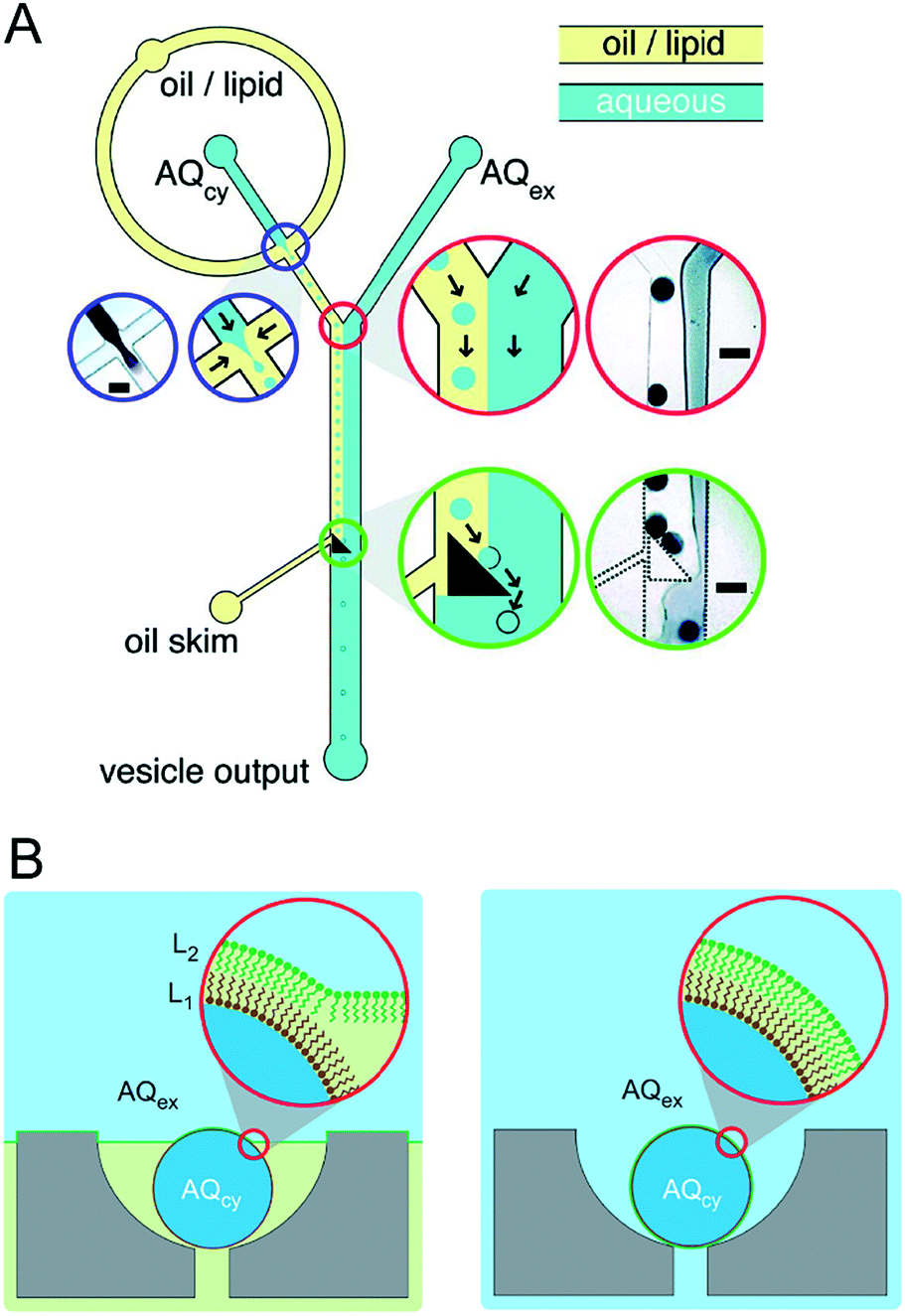 | ||
| Fig. 4 Microfluidic generation of vesicles via on-chip emulsion transfer. (A) Lipid-stabilised water-in oil droplets are transferred from an oil to an external water solution (AQex) with the aid of a microfabricated post. This transfer deposits a second monolayer, resulting in a lipid bilayer encasing the inner solution (AQcy). Reprinted with permission from ref. 65, copyright 2011 American Chemical Society. (B) A lipid-stabilised (L2) water–oil interface is deposited on a lipid-coated (L1) droplet trapped in a hydrodynamic trap. Reprinted by permission from ref. 67, Macmillan Publishers Ltd, Nature Chemistry, copyright 2013. | ||
The second class of technologies are those relying on double emulsion (w/o/w droplets) as droplet precursors. Lipid is dissolved in the oil phase, and a monolayer assembles at all water–oil interfaces. The intermediate oil phase is chosen so that it is partially soluble in the aqueous phase (e.g. chloroform,68,69 hexane,68 toluene,69 oleic acid,70 or octanol71). The intermediate oil phase thus gradually diminishes in size, leaving behind a lipid bilayer. This process is often accompanied by a dewetting phenomenon and often results in an oil lens being trapped within the bilayer.68,72
As discussed in later sections, these methods are often repurposed to generate higher-order architectures. There have also been demonstrations of a whole host of non-droplet based microfluidic techniques to generate vesicles of any size (from SUVs to GUVs), including flow focusing, transient membrane ejection, pulsed jetting, and on-chip electroformation and extrusion.62 These methods however cannot be modified to generate higher-order structures with a fine degree of a control.
3.2 Droplet interface bilayers
DIBs are free-standing lipid bilayers assembled at the interface of lipid-coated droplets of water positioned into contact inside a well of oil. Lipids supplied either directly to the oil (lipid-out) or as a vesicle-dispersion to the water droplet (lipid-in) spontaneously self-assemble at the oil–water interface to form a monolayer-shell encasing each droplet and a lipid bilayer is formed when the droplets are manipulated into contact.73 This was originally shown in open wells with manual manipulation of droplets, with later studies demonstrating that droplets can be manoeuvred into contact using compressive,74 electrohydrodynamic,75,76 gravitational77 and optical forces.78The method was first demonstrated inside a microfluidic channel by Funakoshi et al.,79 who showed the assembly of a bilayer between two aqueous streams inside a microfluidic flow-focusing junction containing lipid-in-oil. The group later reported the use of microfluidic channels to perfuse the contents of a single droplet used to form a DIB.80 The ability to assemble DIBs between two, or a small number of droplets, under continuous flow has also been reported on droplet microfluidic chips with hydrodynamic traps,81 similar in principle to a previous report using chips cast from 3D printed moulds.82
Precisely controlling the position of individual droplets in microfluidic channels can be more readily achieved using passive systems that are not under continuous flow.83 This approach was exploited by Czekalska et al. to generate droplets and position them on-chip to form two-droplet DIBs (Fig. 5).84 Droplets could be dynamically exchanged with replacements, and electrical measurements performed on each new droplet pairings. Using a system of valves, flow of oil could be precisely controlled and droplets positioned inside hydrodynamic traps with further in-line actuators leading to droplet exchange. The authors demonstrated control of the bilayer by shearing the droplet interfaces apart by varying the flow of oil applied from a perpendicularly oriented channel. The ability to exchange droplets was exploited by performing a screening assay where one droplet was prepared with the pore-forming protein alpha hemolysin (αHL), while the second droplet contained a sequence of blocker concentrations. Pore formation and blockade was confirmed using single-channel electrophysiology, which revealed an increase in blocking events in-line with blocker concentration.
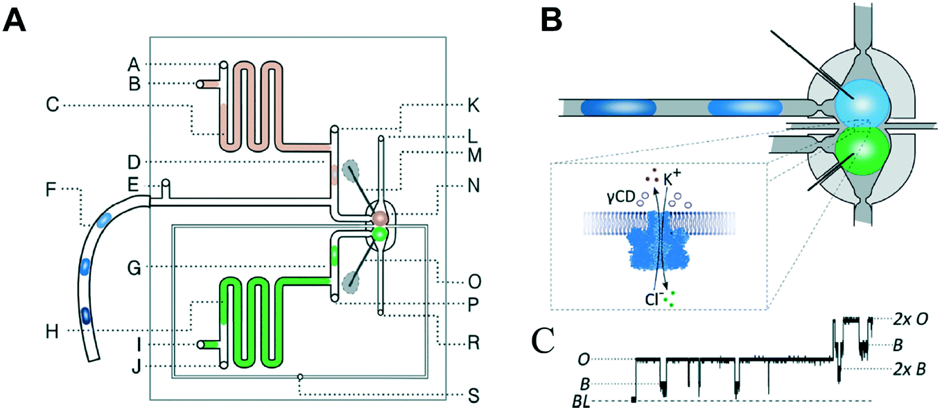 | ||
| Fig. 5 Geometry and operation of the microfluidic device developed by Czekalska et al. (A) Two computer numerical control (CNC) milled polycarbonate plates are bonded in a hydraulic press. Points A, E, J, K and P represent oil inlets, B and I are inlets for aqueous samples, C and H are aspiration modules, D and G are T-junctions, F is a sample inlet, M and O are Ag/AgCl electrodes, N is a hydrodynamic trap, S is an oil inlet for the control channel, L and R are outlets. (B) Enlarged picture of the hydrodynamic trap showing the assembly of a DIB between two droplets. The zoom shows the α-hemolysin pore inserted into the membrane. (C) Electrical recordings of α-hemolysin reconstituted into the DIB (segment of 20 s). Stepwise increases in current from 0 (baseline) to 50 pA (maximum) reflects the incorporation of a single pore. The presence of inhibitor (γ-cyclodextrin) within the pore is seen as a decrease in current by approximately 60%. O – open pore level, 2× O – 2 open pores, B – blocked pore, 2× B – 2 blocked pores. Image modified from ref. 84 with permission from the Royal Society of Chemistry. | ||
Although the DIB system offers several advantages, it does suffer from limitations that arise from assembly in a bulk oil environment. This means that transferring DIBs into a physiological (i.e. aqueous) setting is problematic. Furthermore, the water–oil interface may act as a surface on which amphiphilic bio-molecules may accumulate and/or denature. So far, this aspect has been relatively underexplored in the literature. Finally, the degree of incorporation of oils at the droplet interface may also be an issue.85 This may change the biophysical properties of the membrane and the membrane thickness. It should be noted that DIB membranes have been shown to be capable of hosting a range of transmembrane proteins,73 including mechanosensitive channels,86 and are also capable of displaying the same phase behaviour as ‘oil-free’ membrane structures. This suggests that even if a small quantity of oil is present in the membrane, it does not affect the key processes that model membranes are used to study.87 A final issue concerns the stability of DIBs, particularly as they are not thermodynamically stable structures and droplet coalescence is a recurrent problem. This can be somewhat tackled by increasing the incubation time of the droplets, supplying lipids to both the aqueous and continuous phase,154 and by using lipids such as DPhPC (this is further discussed in section 4.3), although this reduced the membrane compositional parameter space that can be explored using the DIB system. An approach of increasing the concentration of lipids at the oil/water interface through droplet evaporation during incubation may be a promising route to address this problem.88
3.3 Extended droplet interface bilayer networks
Compared to traditional methods of forming model membranes (e.g. black lipid membranes, liposomes and supported lipid bilayers), perhaps the most novel property of DIBs is the ability to connect droplets together to form bilayer networks. The assembly of bilayer networks from several different droplet types is particularly interesting if the bilayers can be functionalised with membrane proteins to yield network architectures that exhibit collective properties. This has been achieved using networks made from a small number of manually pipetted (200 nL) droplets in acrylic wells, in order to construct light-sensors and biobatteries,89 in addition to a range of current rectifiers.90 Manipulation into 3D networks using magnetic beads91 and optical tweezes78 has also been shown.Rapid production of droplets using microfluidics has (i) enabled the construction of larger-scale extended networks made up of thousands of interconnected droplets and (ii) allowed to size of these droplets to be reduced from the hundreds of nL regime to the pL regime. DIB network production was first reported inside microfluidic channels by Stanley et al.,92 who demonstrated both the assembly of linear droplet networks and 3D droplet stacks. The concept was further developed to form asymmetric DIB networks with branched geometries and more well-defined 3D architectures,16 as well as using microfluidics rails guide the assembly of DIB networks by sorting droplets by size.93
The ability to assemble ‘a tissue like material’ consisting of tens of thousands of interconnected droplets arranged into multi-layered DIB networks was demonstrated by Villar et al.,94 using 3D droplet printing (Fig. 6). These architectures could be printed inside an oil environment, with the bilayers functionalised with αHL to establish conduction pathways. Osmatic imbalances could also be used to create networks that could self-fold. This approach was advanced by Booth et al.95 who demonstrated the light-triggered (in vitro) expression of α-HL in 3D printed droplet networks. The method was more recently refined to a higher resolution to enable individual droplets to be targeted within a DIB network, enabling the composition of individual droplets to be defined by the user post-network generation.96
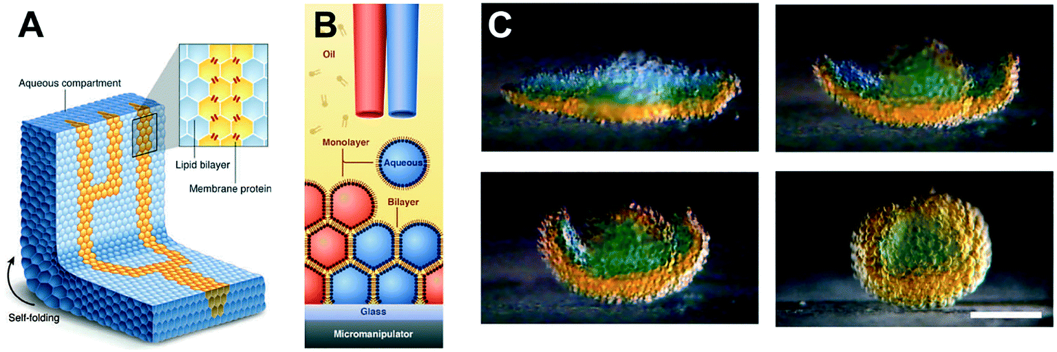 | ||
| Fig. 6 3D printed DIB networks developed by Villar et al. (A) Scheme of a printed droplet network from two different droplet types. The blue droplets contain buffer, while the yellow droplets contain α-HL pores. (B) Illustration of the printing process of ∼65 pl droplets in lipid–oil. (C) Photographs showing osmotically-driven self-folding of a 3D DIB network. A flower-shaped 3D network was printed from droplets containing 80 mM (orange) and 8 mM (blue) KCl and shown to self-fold into a hollow sphere over 8 hours. Scale bar = 200 mm. Image modified from ref. 94 with permission from the American Association for the Advancement of Science. | ||
3.4 Multisomes
Multisomes are multi-phase systems that are lipid-stabilised w/o/w double emulsions. They consist of one or more internal water droplets that are encased inside in larger oil droplets dispersed in a continuous aqueous phase. Bilayers are present at the point of contact between the inner droplets themselves, and between the inner droplets and the external aqueous solution. Multisomes were first introduced by Bayley et al.12 to address the main limitation of DIB architectures, which is that they cannot be dispersed in physiological (aqueous) environments. The presence of bilayers means that communication between distinct compartments and/or the external environment is possible after incorporating protein pores. Multisomes are traditionally formed one-by-one, through manual pipetting of water droplets into a larger o/w droplets.12,97 Multisomes formed in this way were shown to be capable of in situ release of chemicals triggered by temperature and pH changes in the internal compartment droplet that destabilise its membrane, leading to rupture and exposure of its content.12Recent years have seen the development of microfluidic devices to automate multisome production, reduce their dimensions, and increase the generation throughput compared to the manual injection method, whilst still maintaining high control over the size, number and content of compartments.46,48,98 In one example, a PDMS device containing defined hydrophilic regions that was patterned using layer-by-layer deposition of charged molecules was fabricated.48 In another example, w/o droplets were generated in a hydrophobic glass capillary section, followed by encapsulation in larger oil droplets which were subsequently encapsulated in a rigid alginate shell (Fig. 7).98 Glass capillaries were mounted and controlled via a 3D printed device. Recently, multisomes and inverted multisomes (o/w/o emulsions) were generated using the same device design.46 This was realised via a versatile technique based on the selective modification of a microfluidic channel network. Selected channels were made hydrophilic by depositing PVA molecules following plasma oxidation. Hydrophobic channels were excluded from this treatment by applying a continuous air flow to these regions to prevent infiltration of the polymer solution.
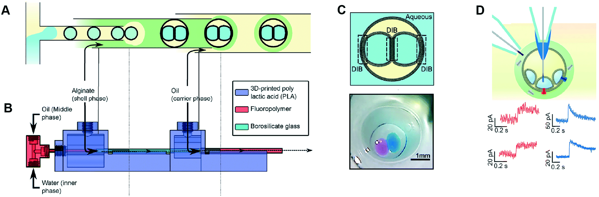 | ||
| Fig. 7 Microfluidic generation of multisomes. (A) Microfluidic generation of multisomes encased in a rigid alginate shell using glass capillaries. (B) Side-view schematic of the 3D printed device within which the glass capillaries are embedded. (C) Schematic of a generated two-compartment multisome and relevant image. (D) Protein insertion evens (α-hemolysin pores) is detected across the bilayer is detected (red traces). Transient spikes are also observed (blue spikes) due to protein insertion into neighbouring bilayers. Subfigures reproduced from ref. 98 with permission from Angew. Chem. | ||
Multisomes formed using microfluidics have been shown capable of acting as microreactors for in situ synthesis of drug-like molecules (Fig. 8).48 This was shown by encapsulating fluorogenic pyrylium – a membrane impermeable compound – in the first inner droplet, while the neighbouring droplet was loaded with a membrane permeable primary amine. Amine gradually diffused through the formed bilayer into the adjacent pyrylium-loaded droplet.
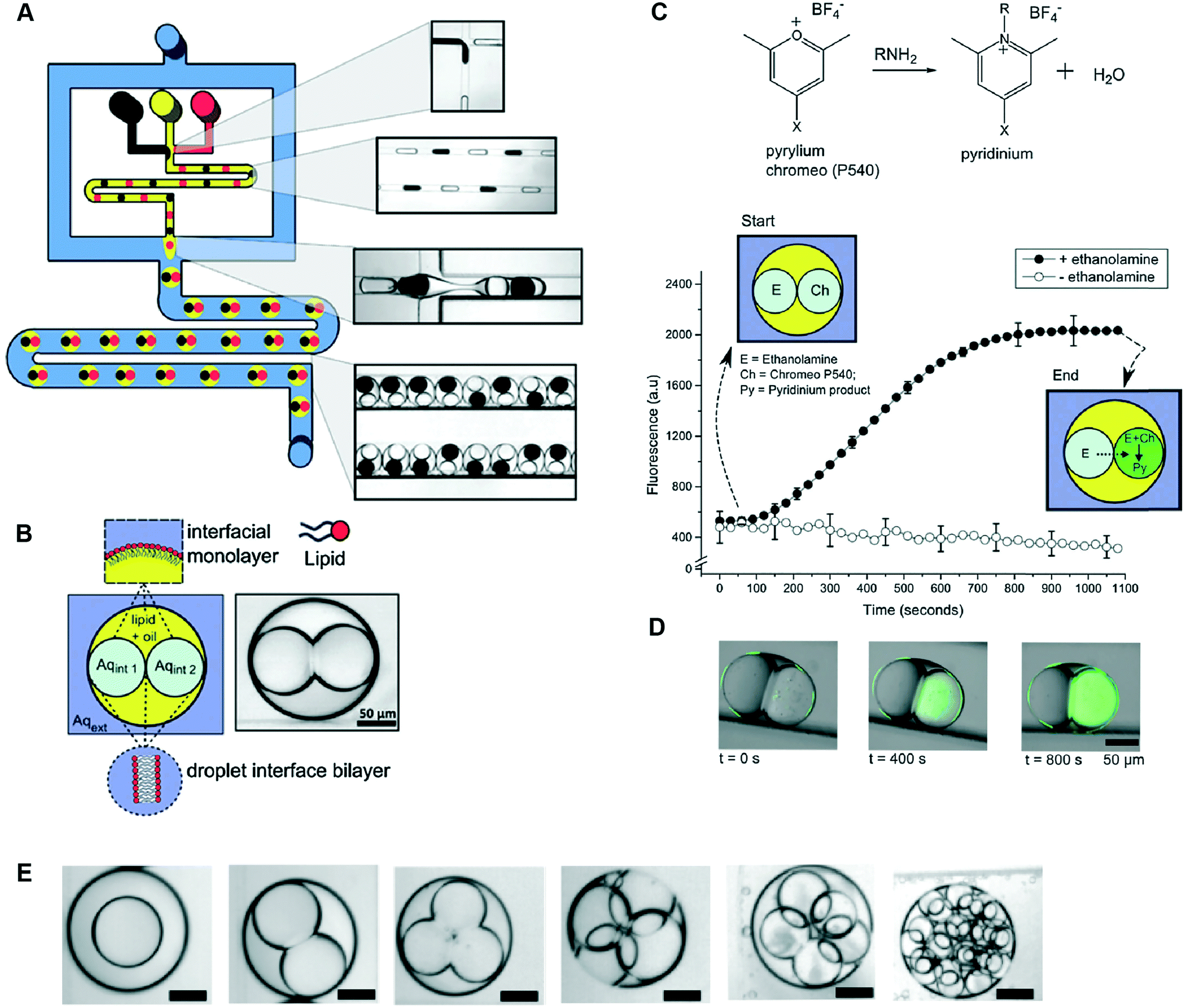 | ||
| Fig. 8 Microfluidic generation of multisomes using a PDMS-based microfluidic device and their application as reactors for on-board synthesis. (A) Schematic of device and corresponding brightfield images of generated droplets and double emulsions. W/o droplets are generated at a hydrophobic FFJ, while o/w droplets are generated at a hydrophilic FFJ. (B) Schematic of a two-compartment multisome. (C) Pyrylium and a primary amine are spatially segregated in the two compartments and gradually form a fluorescent pyridinium product as ethanol-amine diffused through the DIB. (D) Fluorescence/brightfield composite image of the reactor at distinct time intervals. (E) Examples of multisomes with 1, 2, 3, 4, 5 and 20 inner compartments. Figure reproduced from ref. 48 with permission from Royal Society of Chemistry. | ||
We note that there have been several examples of multisome-like structures generated as precursors to lipid vesicles via microfluidics.68–70,72,99–102 In addition, with surfactant stabilised structures, higher-order triple, quadruple, and quintuple (w/o/w/o/w/o) emulsions have been formed using microfluidics, with multiple droplet formation and encapsulation modules;20,103,104 lipid-based multisome equivalents of these have yet to be successfully generated.
3.5 Polymersomes
Polymersomes are spherical structures consisting of an aqueous core encased by a single polymer-thick membrane. Their building blocks are mono- or bilayers of amphiphilic block copolymers which, similar to lipids, self-assemble spontaneously in an aqueous environment. The hydrophilic fraction of the block copolymer determines the resulting architecture, which can be planar, spherical or cylindrical.105 There are other types of polymers which assemble as bilayers, such as di-block copolymers, comb copolymers and dendronised copolymers. Polymersomes have been developed as alternatives to liposomes because of their physical and mechanical robustness, their enhanced biochemical resistance to degradation and their ease to synthesise and tune their chemical structure and permeability. Nevertheless, they lack the biological relevance of lipids and, therefore, their use as cell membrane models to study biological phenomena has been limited. There have been also successful efforts toward functionalising the polymer membrane with transmembrane channels, yielding the formation of synthosomes.106Polymersomes can be formed using a number of methods available for liposome fabrication, such as film rehydration, electroformation, extrusion, dissolution direct injection, and double emulsion production using microfluidics.107–109 Compared to microfluidic approaches, bulk methods for polymersome production suffer the same limited control over the size, monodispersity and throughput as their lipid-membrane bound counterparts. Compartmentalised polymer-based structures have been engineered using microfluidics in the form of multicompartment polymersomes110 and polymersomes-in-polymersomes.111 Multi-compartment polymersomes have been generated using glass capillary microfluidics from w/o/w emulsions with block-copolymers as the stabilising agent110 (Fig. 9A). In this system, the intermediate oil phase consists of a volatile solvent mixture such as chloroform and hexane, which is subsequently removed via evaporation. As the solvent evaporates, the copolymers at the w/o and o/w interfaces are attracted towards each other to form a polymer shell (Fig. 9B). Polymersome-in-polymersome systems have been implemented using capillary microfluidic devices (Fig. 9C), where polymersomes are generated and subsequently encapsulated in larger polymersomes.111 These systems have been used for the controlled release of multiple distinct compounds. In a three-compartment system, the membranes of the outer, middle and inner compartment selectively ruptured depending on the presence or absence of (PEG)-b-poly(lactic acid) (PLA) diblock copolymers on each membrane (Fig. 9D). In the absence of PLA homopolymers, all membranes sequentially start to rupture, starting from the outermost membrane working inwards through the middle to inner membranes. Whereas, upon the presence of PLA homopolymers in the outer and middle membranes, the innermost membrane first ruptures due to the spontaneous degradation of the PLA in water.
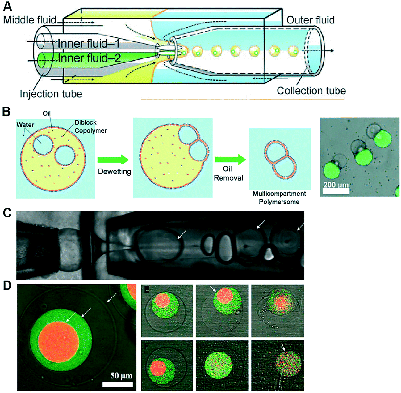 | ||
| Fig. 9 Microfluidic generation of compartmentalised polymer structures. (A) Microfluidic generation of multicompartment polymersomes using glass capillary devices. (B) Formation mechanism of multicompartment polymersomes from double emulsion drops with multiple inner droplets and relevant fluorescence/brightfield composite image of the systems. (C) Microfluidic generation of polymersome-in-polymersome systems using glass capillary devices. (D) Confocal microscope images showing triple polymersomes. (E) Series of images showing sequential dissociation of membranes from the outermost to the middle of triple polymersome. (F) Series of images showing sequential dissociation of membranes from the innermost to the outermost of triple polymersomes. Subfigures (A) and (B) are reproduced from ref. 110 with permission from Angew. Chem. Subfigures (C) and (D) reprinted with permission from ref. 111, copyright 2011 American Chemical Society. | ||
3.6 Multi-compartment vesicles
Multi-compartment vesicles comprise two or more inner compartments that are separated from one another by a single bilayer and share a continuous external membrane. They can hence be considered to be hemi-fused. These are distinct from vesicle aggregates, where individual vesicles adhere to one another through specific112,113 and non-specific forces,114 which do not share a membrane. Methods to form controlled vesicle aggregates on-chip have been developed by Robinson et al., by trapping GUVs in a micro fabricated structures.115 These devices were fitted with electrodes which enabled controlled electrofusion. Optical trapping methods have also recently been used to form networks of adherent GUVs, with two membranes dividing the internal contents of each compartment from one another.116 In this case fusion was achieved by exploiting gold nanoparticle resonance in the optical trap, leading to a local temperature jump and degradation of the membrane fabric. Currently, the only routes available for the controlled assembly of multi-compartment vesicles (as opposed to vesicle aggregates) are droplet-based methods, with no self-assembly techniques available for their construction.One approach is to use a modified version of the emulsion phase transfer method for vesicle generation;63 instead of driving a single droplet through a water–oil interface, multiple droplets may be driven through simultaneously, where they become encapsulated by a surrounding lipid bilayer (Fig. 10A).117 The size of the droplets (and of the final vesicle compartments) could be defined a priori by dispensing different aqueous volume via a microdroplet dispenser. Compartments smaller than ca. 100 μm in radius could not reliably be formed as these did not successfully penetrate the water/oil interface of the column. The number of compartments could be varied simply by ejecting a set number of droplets, and compartment contents easily controlled as these were those of the droplet precursors. Vesicles formed via this method have levels of trapped oil in the membrane, which either form as oil lenses that eventually dewet and are ejected, or accumulate at the bilayer vertices where it remains trapped.117 Such vesicles have been used in artificial cell applications as a route to achieve cell-like organisation of content and function through spatially segregated protein synthesis (Fig. 10B).8 In this case, an in vitro transcription–translation (IVTT) system was used for GFP synthesis in one compartment and RFP synthesis in another. Multi-compartment vesicles have also been used as chemical microreactors, with distinct enzymatic reactions occurring in each compartment, and reaction intermediates diffusing into adjacent compartments through embedded protein pores (Fig. 10C).9
 | ||
| Fig. 10 Multi-compartment vesicles. (A) Schematic of the experimental setup used for their generation. Multiple lipid-coated droplets are driven through a second lipid interface using a density gradient. (B) Image of GFP (green) and RFP (red) proteins being produced in different compartment using a cell-free expression system. This demonstrated spatial organisation of function in a synthetic cell. (C) Spatially segregated vesicle microreactors. Enzymes responsible for each step of a three-step cascade were encapsulated in distinct compartments. Reaction intermediates could translocate between compartments through embedded pores, leading to the production of a fluorescent dye over time (graph and fluorescent image). Panels A and C reproduced with permission from Macmillan Publishers Ltd, Nature Communications, ref. 9, copyright (2014). Panel B reproduced from ref. 8 with permission from the Royal Society of Chemistry. | ||
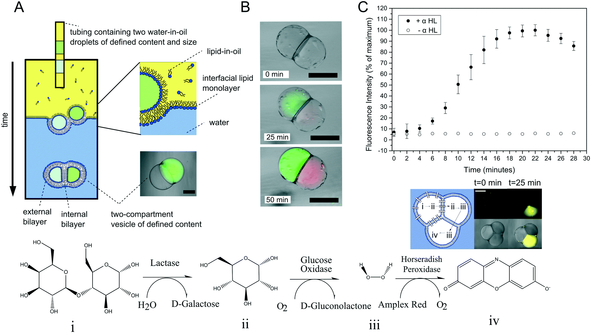
The method above is low-throughput, with vesicles formed one-by-one though manual pipetting of droplets. Recently Deng et al. addressed this limitation by developing a microfluidic chip capable of multi-compartment vesicle generation through dewetting72 of w/o/w double emulsion with multiple inner aqueous cores (Fig. 11A).68,118 Although full dewetting does not occur with lipids as surfactants, it does occur when lipids are supplemented with up to 5 wt% Pluronic surfactant. Their microfluidic device consisted of four steps: droplet generation; droplet pairing; encapsulation; and dewetting. By altering flow rates, it was possible to form vesicles with multiple (up to 5) compartments. The presence of Pluronic surfactant did not appear to adversely affect the encapsulated biochemical machinery, including IVTT synthesis and membrane-protein insertion. Despite the fact that the added surfactant is largely biocompatible for some application (e.g. those that are sensitive to membrane composition and mechanical properties), the presence of this additive may be undesirable, and pure lipid systems may need to be developed.
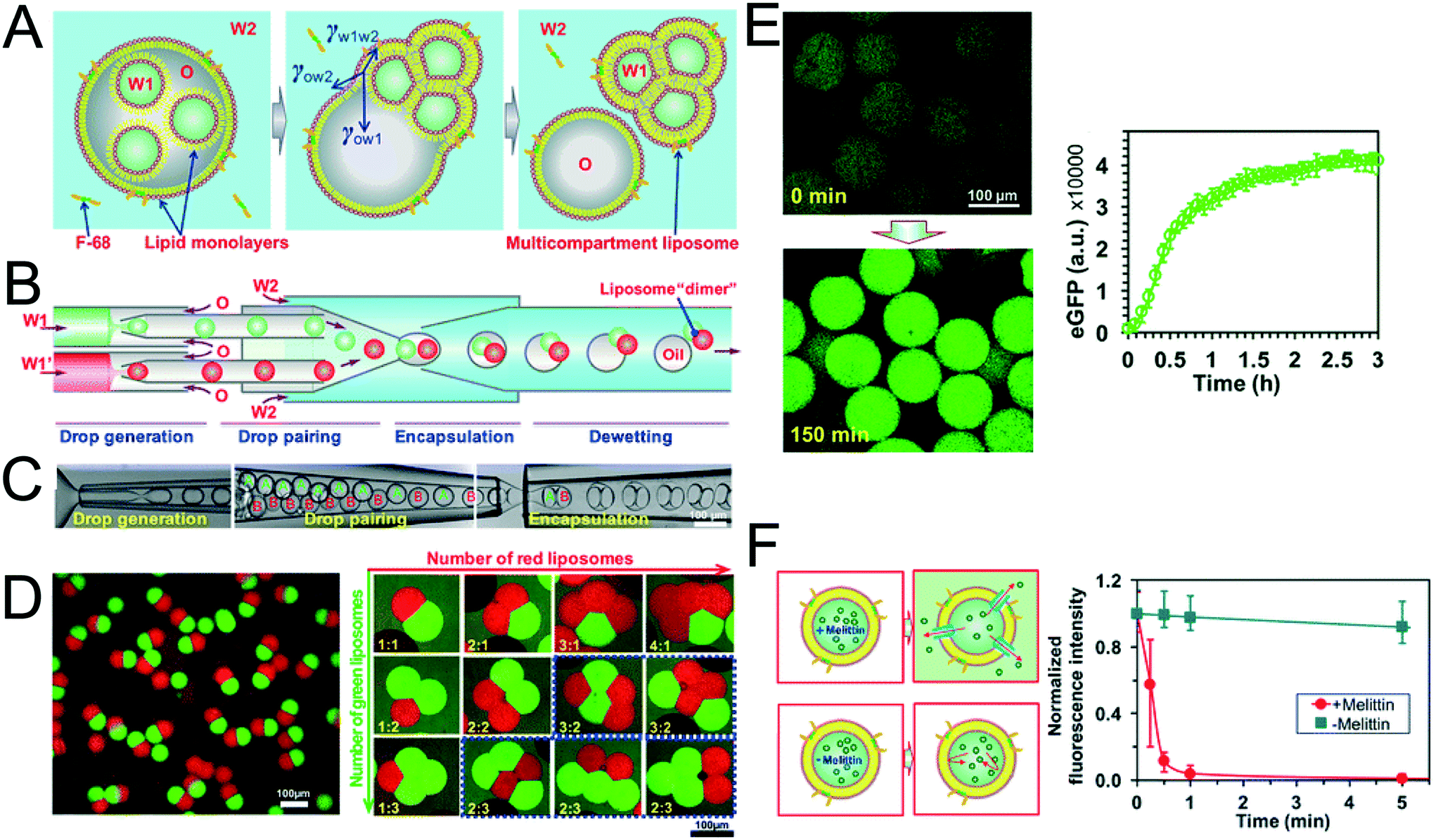 | ||
| Fig. 11 Multi-compartment vesicles using double emulsions as templates. (A) Cartoon showing lipid-coated encapsulated droplets dewetting from the double emulsion (B) schematic and (C) microscopy images of capillary microfluidic device used to generate two-compartment vesicles. (D) Microscopy images of two-compartment vesicles with different dyes in each compartment (left) and vesicles with up to 5 compartment with controlled structures and configurations. (E) IVTT of eGFP in liposomes and corresponding expression kinetics. (F) Insertion of melittin into liposome bilayer and corresponding kinetics of time-dependent release of calcein fluorescence. Reproduced with permission from ref. 68, copyright 2016, American Chemical Society. | ||
3.7 Vesicles-in-vesicles
Vesicles-in-vesicles, also referred to as vesosomes or nested vesicles, can take different forms, including multi-layered membrane structures that adopt an onion-like arrangement and several vesicles that are encased in a larger vesicle.10,11,119–122 Although bulk self-assembly methods for their formation have existed for some time, it has been only recently that on-chip methods were developed by the Huck group.123The strategy employed involved a glass capillary device to form lipid-stabilised w/o/w double emulsions, which then de-wetted to yield vesicles (Fig. 12A). These vesicles were then re-injected into a second device as the inner aqueous phase of larger w/o/w droplet which underwent a second dewetting process to yield vesosomes (Fig. 12B). This concept could be iterated several times to yield third-order vesicles-in-vesicles-in-vesicles (Fig. 12C), although with every added step the overall yield was substantially reduced.
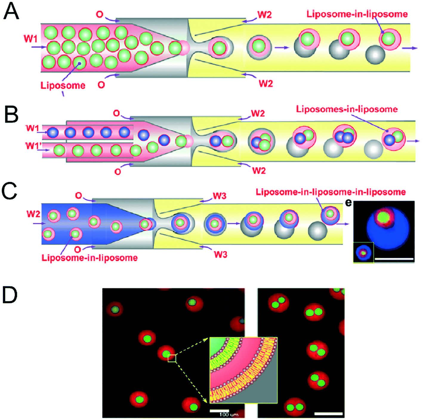 | ||
| Fig. 12 Microfluidic construction of vesosomes using double emulsions. (A) Cartoon showing vesicles being encapsulated in droplets to form lipid-stabilised double emulsions. These dewet to form vesicles-in-vesicles. (B) By feeding in several inner-vesicles, higher order vesosomes can be generated. (C) By iterating the above procedure vesicles-in-vesicles-in-vesicles can be produced. (D) Microscopy images one- and two-compartment vesosomes. Reproduced with permission from ref. 123, copyright 2016, American Chemical Society. | ||
This method enabled control over the dimensions of both the internal and external compartments, and of the number and configuration of the internal compartments. Different sizes of vesicles were encapsulated in a larger parent vesicle using the same device. With capillary microfluidics droplet sizes are influenced by the capillary number,24 which is a function of the orifice size and flow rates, allowing control to be achieved in principle. The encapsulated cargo could also be user-defined for each compartment. The yield of giant vesicles-in-vesicles was 60%. This is in contrast to bulk vesicle formation strategies, where giant vesicles-in-vesicles are only formed stochastically and with no control.19 The encapsulation efficiencies for large, charged, biomolecules were also high, in keeping with droplet-based methods for vesicle generation.
The versatility of this approach was further demonstrated by the generation of both concentric and multi-compartment architectures, achieved by altering the flow rates of the device. By changing the device design it was also possible to form, for example, two compartment vesosomes, where the content of each encapsulated vesicle differed. Such level of control of compartment number, content and size could not be achieved using alternative non-microfluidic methods.124
Vesosomes bear an organisational similarity to multi-organelle eukaryotic cells. Building on this analogy, vesosomes containing a nucleus-like inner compartment were constructed, which contained the components necessary for in vitro transcription of RNA from a DNA template.123 The surrounding ‘cytoplasmic’ compartment, on the other hand, contained a coupled in vitro transcription and translation reaction.
A related structure to vesosomes are multi-lamellar vesicles, where there is no significant aqueous layer between the individual bilayers. These are stochastically and uncontrollably formed using bulk vesicle generation methods.19 Using microfluidics, however, control over vesicle size, number of lamellae, and the lipid composition of each individual leaflet can be achieved. This was shown by Matosevic et al., who fabricated a device where lipid-stabilised w/o droplets were confined in hydrodynamic traps in a microfluidic chamber.67 Individual monolayers were then deposited layer-by-layer by flowing through a water–oil phase boundary of defined lipid composition. This allowed multi-lamellar membranes to be formed with programmable leaflet content.
It should also be noted that recently Nuti et al. demonstrated the microfluidic production of multi-vesicular droplets (vesicles in droplets), that retain the biological relevance of their vesosome analogues, yet are easier to use and control.125 These were formed by encapsulating vesicles generated off-chip into droplets using a FFJ, where encapsulation numbers followed a Poisson distribution. A compartmentalised two-step enzymatic cascade was demonstrated using enzymes present in the interior of the encapsulated vesicle ‘organelles’ and the external vesicle ‘cytoplasm’.
4. Discussion
4.1 The microfluidic advantage
Microfluidics offers several advantages for multi-compartment membrane generation compared to the alternatives. Crucially, it enables the production of higher-order structures, which simply cannot be formed with any fine degree of control over the size, dispersity, number, content, and membrane composition of the multiple compartments using bulk generation strategies. Microfluidics technologies also allow encapsulation of large charged molecules including DNA and proteins. For structures such as DIBs and multisomes, microfluidics allows increased generation throughput and reduction in size, allowing extended 3D networks of cell-sized droplets to be generated.16,94 This significantly outperforms other methods, such as injection and manipulation via electrodes73 or optical traps.126In theory, an upper limit for generation throughput is given by the frequency of droplet generation. This typically stands at tens of kHz,25 although these high figures were obtained using surfactants and not lipids as stabilisers, and it is likely to be lower for membrane systems. This figure also does not take into account limitations imposed by post-droplet manufacture steps, for example second-order encapsulation to form double emulsions and expulsion from the microfluidic device into a bulk environment. In terms of size, droplets as low as several hundred nm can be generated using droplet microfluidics,25 although it should be noted that most multi-compartment membrane constructs lie in the region of 5–100 μm diameter regime. Examples of smaller multi-compartment constructs are not available, possibly due to a reduced interfacial membrane stability at these dimensions. For such constructs to see clinical applications, as drug delivery vehicles for example, technologies to relieve this bottleneck need to be developed.
4.2 Fabrication techniques and associated challenges
Although microfluidics as a platform has significantly aided many fields over the last two decades, many technical barriers to further adoption remain. One of these is associated with manufacturability. Universal, accessible and affordable manufacturing technologies are essential in order to continue democratising the fabrication of microfluidic devices.In general, there exists a wide range of manufacturing technologies for engineering microfluidic devices capable of generating compartmentalised membrane systems. As summarised in Table 2, these include; wet etching of glass and Si, PDMS soft lithography, glass capillaries, computer numerical control (CNC) micromilling, hot embossing, injection moulding, 3D printing and dry film resist technology.156 Methods to fabricate PDMS-based devices by soft lithography and devices incorporating glass capillaries are the most widely reported. Less reported techniques include that of wet etching to produce Si-based devices127 and micromachined cyclic olefin copolymer (COC) sheets.128
| Compartmentalised system | Fabrication method | Order of magnitude | Topology of microfluidic device |
|---|---|---|---|
| Multisomes | Soft lithography46,48 | 50–300 μm | 2 FFJs |
| Glass capillaries98 | 500–1000 μm | Double co-axial microfluidic capillaries | |
| Dry film resist technology and multi-layer lamination156 | 16–200 μm | 2 FFJs | |
| Multicompartment polymersomes | Glass capillaries110 | 10–60 μm | Multiple co-flow glass capillaries and flow focusing |
| Polymersomes-in-polymersomes | Glass capillaries111 | 50–300 μm | Co-flow and flow focusing glass capillaries |
| Multi-compartment vesicles | Single-droplet phase transfer8,9,117 | 200–700 μm | Tubing with droplets above phase-transfer column |
| Glass capillaries68 | 20–200 μm | Multiple sequential co-axial capillaries | |
| Vesicles-in-vesicles | Glass capillaries123 | 50 μm (inner vesicles) | Multiple sequential co-axial capillaries |
| 100 μm (outer vesicles) | |||
| Vesicles-in-droplets | Soft lithography125 | 50 μm (droplets); 2–30 μm (vesicles) | Vesicles formed off-chip, droplets formed with FFJ |
| Multi-lamellar vesicles | Soft lithography67 | 50 μm | 1 FFJ and droplet traps |
| Droplet interface bilayers | CNC milled wells79,130 | >1 mm | Droplets dispensed manually into place |
| CNC milled microfluidics84 | 780–875 μm | Droplets positioned automatically under pressure | |
| Laser cut plastics131 | 725 μm | Sliding wells allowing bilayer assembly/disassembly | |
| Soft lithography81 | 125 μm | 1 FFJ and droplet traps | |
| Optical traps126 | 15–30 μm | Droplets assembled manually inside device | |
| Droplet interface bilayer networks | CNC milled wells/wells89,132 | 725 μm | Droplets dispensed manually into place |
| Microfluidic tubing16,133 | 200–700 μm | Droplets assembled inside tubing | |
| Soft lithography93 | 105–140 μm | FFJ and microfluidic rails | |
| Droplet printing94,95 | 75–500 μm | Droplets deposited using a print head |
Ultimately, the choice of material and fabrication technology is predominantly based on the desired application; biocompatibility, optical transparency, compatibility with organic solvents are among the many criteria for selecting the appropriate material. The wettability of the material is also a key determining factor when engineering multicompartment architectures; the inherent hydrophobicity of PDMS (water contact angle >100° (ref. 129)), as well as its compatibility with organic solvents and optical transparency, have established it as the material of choice. Yet despite these advantages, soft lithography is a time-consuming, and reagent-heavy fabrication technology that is typically restricted to small-scale in-house manufacturing. Aligning individual photoresist layers in more complex devices with multiple channel depths is also challenging, particularly when producing structures with high aspect ratios. The production of master templates also requires the use of centralised microfabrication facilities (cleanrooms). Alternative approaches using 3D-printed moulds have been showcased, but currently lack the feature resolution offered by photolithography.
Glass capillaries are commercially available and potentially reusable. However, a limit to their wider adoption is that alignment into devices is difficult and often performed manually. Efforts to automate their incorporation into devices using 3D-printed support bases are showing promise.98 Glass and Si-based devices are produced by combined photolithography and wet etching in controlled microfabrication environments allowing fabricated devices to benefit from excellent channel resolution; however, production is expensive and time-consuming. Rapid prototyping technologies for microfluidic device fabrication have lately emerged,128 however, very few examples to date have demonstrated lipid-based system generation.
There are several challenges to be overcome in order to facilitate the widespread adoption of microfluidics to generate compartmentalised membrane-based systems. With the steadily increasing desire to incorporate multiple different proteins and molecular machineries into bilayer systems, there has never been a greater demand to integrate multiplexed fluid handling capabilities into devices. New biocompatible materials also need to be leveraged together with more robust surface modification methods that are long-lasting, straightforward and effective with lipids. Moreover, these features need to be streamlined and integrated into large-scale production technologies.
There is also a need for modular components to exchange material information between each other seamlessly, requiring the standardisation of connectors and interfacing strategies. This feeds directly into the need for further system integration, the so-called lab-on-a-chip versus chip-in-a-lab argument, which mandates better instrumentation technologies (pumping, heating/cooling, detection) as well as integration of these distinct modules into a single multi-functional unit.
One key difficulty relating to compartmentalised systems in particular relates to surface chemistry (i.e. wettability), especially when forming structures that exist in bulk aqueous environment (vesicles and multisomes). Devices for form these invariably have some regions of the device which are hydrophobic, and others which are hydrophilic. This is technically difficult as it either requires the assembly of a device made up of different materials in different regions or selective surface treatment of defined regions of the device. A further complicating factor is that although many surface modification techniques change the wettability enough to controllably form stabilised surfactant–stabilised droplet, when using lipids, this becomes less reliable, with wetting of droplets on channel walls being a persistent issue. When forming structures in a bulk oil environment (e.g., DIBs), this is less of a problem, as many microfluidic devices substrates naturally have a high level of hydrophobicity.
Another issue is the level of control with respect to connectivity, which is especially important in the case of large-scale DIB networks. Using classical droplet microfluidics, control over the position of individual droplets with defined compositions within a network is difficult to achieve. Printing droplets one-by-one circumvents this, hence the most complex architectures that have been assembled using this method.94
Other practical barriers that must be overcome include developing more effective methods for ejection of membrane constructs out of the device, introduction of stabilisers to improve their endurance and lifetime, and developing new ways to achieve incremental levels of compartmentalisation. So far, the reported carriers mostly comprise of sub-compartments of the same nature. Generating compartments composed of distinct encapsulated materials and membranes of different composition will enable control over diverse functionalities and the introduction of multi-step stimuli-responsive processes.
Given its versatility, many of these issues could be addressed by 3D printing, which presents key advantages in simplifying the fabrication of devices by removing the requirement for a cleanroom and specialised engineering infrastructures.134 To this end, 3D printing offers the ability to produce devices rapidly, with open-source interfacing connectors, in an ever-increasing range of transparent and biocompatible materials.135 Although model membranes have already been assembled on 3D printed substrates using manually pipetted droplets,136 the future of this technology promises to deliver a new generation of entirely 3D printed continuous-flow microfluidic platforms, as opposed to integrating 3D printed parts alongside conventional microfluidic components.98 Again, the key challenges toward ensuring this outcome will be the ability to control the wettability of surfaces together with fine control of feature resolution.
4.3 Membrane stability and the choice of lipids
For many applications, the stability of the membranes is critical. This will vary according to size, presence of oil phases, number of sub-compartments and the type of lipid or lipid mixtures being used. DIBs and multisomes are notoriously fragile, since the interfacing bilayer has a high tendency to rupture, leading to droplet fusion and loss of the bilayer interface. The lipid 1,2-diphytanoyl-sn-glycero-3-phosphocholine (DPhPC; Fig. 13A) has been found by several researchers to increase membrane stability73,137 in structures which rely on lipid monolayer assembly at a water/oil interface due to the branched methyl groups in the lipid tail regions, and is chemically stable due to complete saturation of the chains. DPhPC has, therefore, become the lipid-of-choice in membranes formed via droplet microfluidics. The inclusion of PEGylated lipids has also been reported to stabilise membranes,95,138 as has the use of alginate gel to provide a robust scaffold that protects membranes from mechanical perturbations.98 Alternative lipids such as DOPC and POPC are thought to produce more unstable DIBs and multisomes as monolayers do not spontaneously assemble into the tightest possible configuration at the water/oil interface.88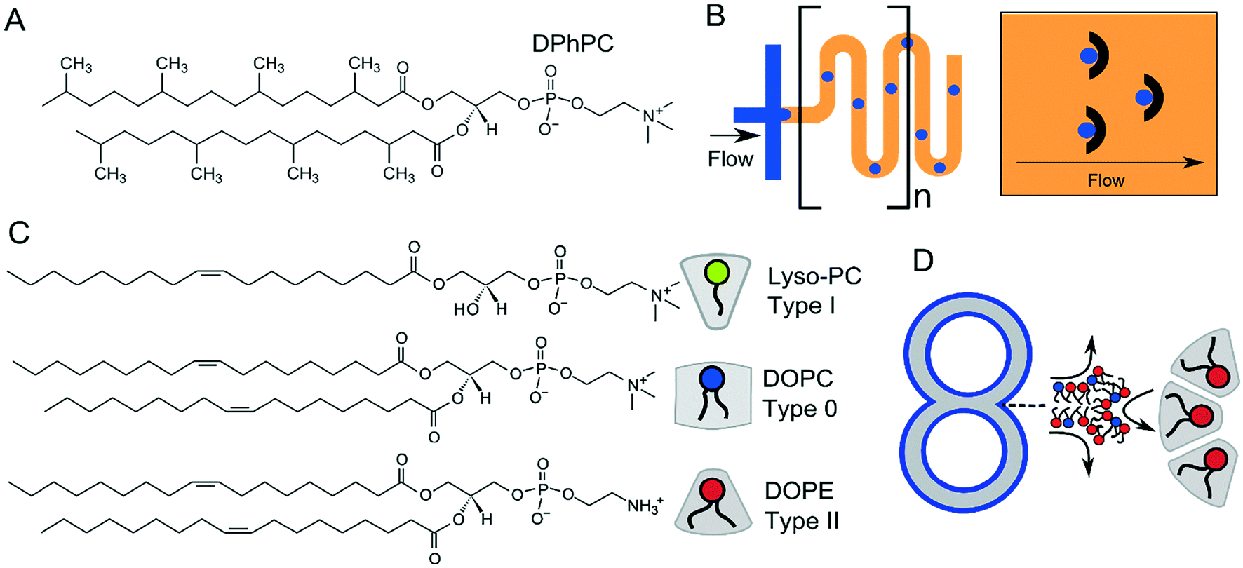 | ||
| Fig. 13 (A) Structure of DPhPC, which is the most common lipid used in multicompartment membranes due to the increased stability afforded by the branched –CH3 in the acyl chain region. (B) Serpentines (meanders) and microfabricated droplet traps are sometimes incorporated into devices to allow sufficient flow of lipid-in-oil around the droplet, leading to efficient monolayer adsorption and droplet stabilisation. (C) Chemical structure of type I, type 0, and type II lipids together with their intrinsic shape, determined by the size of their headgroup and acyl chains, which governs their side-by-side packing. Type I lipids have a preference to pack curving away from the bulk water, type II towards the bulk water, and type 0 have no preference for curvature. (D) Incorporation of type II lipids will stabilise highly curved regions of multi-compartment architectures. | ||
Vesicles are inherently more stable structures and hence a wider repertoire of lipids have been used for their production using microfluidics. This includes both saturated and unsaturated lipids, as well as cholesterol, which has allowed vesicles with coexisting domains to be produced.54 The use of different lipid types allows the rich phase behaviours that membranes possess to be used for the introduction of functionality, for example, membrane rupture during phase transitions.12 Lipid synthesis is a laborious and time-consuming process. The availability of an ever-increasing library of commercially available lipids with a host of conjugated chemical moieties (e.g. gold nanoparticles, azides and alkynes for click chemistry, crosslinking substituent etc.) will no doubt aid the generation of functional membrane systems going forward.
Lipid-stabilised droplets are the precursors of most multi-compartment membranes formed using microfluidics. As such, the effect of stabilisation time is important when considering membrane stability. If aqueous droplets do not have an effective lipid monolayer surrounding them, they will merge upon contact with any another aqueous phase. Generally, the longer aqueous droplets are incubated in lipid-in-oil solutions, the lower the probability of merging events.73,137 Microfluidic devices are thus sometimes designed with stabilisation time in mind. Serpentine channels are often incorporated into them to increase the time droplets spend in a confined environment allowing the adsorption of lipid monolayer before they meet another aqueous phase (Fig. 13B). Alternatively, devices may allow droplets to be sequestered in microfabricated traps, with lipid-containing oil passed through (Fig. 13B), enabling effective monolayer stabilisation.67 Microfluidic approaches are also aided by the advection supported transport of lipids to the interface, which has also been suggested to drastically reduce stabilisation time.139
In addition, the phase which contains the lipid is also important. When lipid is supplied to the aqueous phase (as large unilamellar vesicles; lipid-in) monolayer formation is often quicker than when it is supplied in the oil phase (lipid-out).137
One final aspect to consider is that of intrinsic lipid curvature (Fig. 13C).140 Depending on their chemical structure, lipids can have a preference to pack and curve either towards or away from the bulk aqueous solution, or have no intrinsic preference for curvature. These are known as type I, type II, and type 0 amphiphiles respectively. For example, lyso-phosphocholine (lyso-PC) has a larger headgroup cross-sectional area compared to its acyl chain region by virtue of it having only one fatty acid tail. It, therefore, will tend to pack towards the aqueous phase to form micellar structures. The opposite is true of PE (phosphatidylethanolamine) lipids (type II). These have hydrogen substituents on their headgroups (as opposed to methyl ones) making them smaller compared to the tail regions, leading to the formation of inverse phases. As on the molecular scale, membrane constructs in the μm regime are essentially flat, type 0 amphiphiles (e.g. 1,2-dioleoyl-sn-glycero-3-phosphocholine, DOPC) which have no preference for curvature are usually used. However, multi-compartment systems often have regions of high curvature at the inflexion points where two compartments meet, and the use of other lipid types (e.g. type II) may be useful in stabilising these structures (Fig. 13D).141,142 Curvature effects such as these will be particularly important as these constructs are scaled down, where the effects of membrane curvature become more pronounced.
4.4 Efficiency and yield
Arguably, the most important parameter when considering the suitability of a particular microfluidic device for multi-compartment membrane generation is the overall efficiency and yield of the process. Efficiency can be defined in terms of conversion, encapsulation, and incorporation efficiencies (Fig. 14).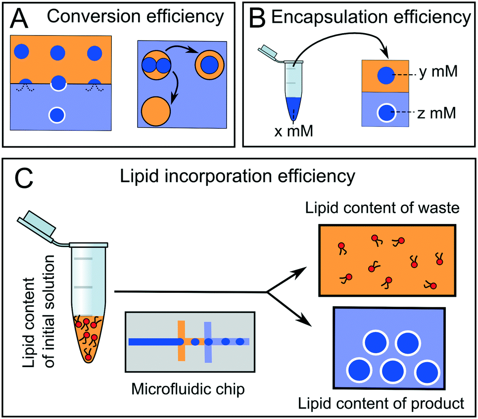 | ||
| Fig. 14 Different types of efficiencies associated with microfluidic membrane generation. Yellow = oil phase, blue = aqueous phase. (A) Some droplets will merge with the adjacent aqueous phases leading to bilayer destruction and reduced conversion efficiency. (B) Encapsulation efficiency refers to the concentration of chemical species pre-encapsulation (x) compared to that of the compartmentalised droplet (y) or membrane-bound construct (z). (C) Lipid concentration efficiency refers to the quantity of lipid in the original lipid-in-oil solution compared to the total lipid quantity in the membrane products. | ||
Conversion efficiency refers to the proportion of droplets that end up in the final multi-compartment construct compared to the total number of droplets generated in the first place. In microfluidic membrane generation, be it phase transfer or double emulsion templated approaches, a high proportion of w/o droplets will merge when encountering a second aqueous phase (Fig. 14A). Some of the first devices reported in the literature had low conversion efficiencies of between 1–5%,65 although these have since been improved upon, with efficiencies reaching as high as 94%.68,123 We note that the conversion efficiency may not be overly critical with microfluidic methods, as the production of droplet precursors can be high-throughput enough to accommodate for low efficiency.
Encapsulation efficiency is the concentration of a compartmentalised molecule versus the bulk solution (Fig. 14B).143–145 This drastically varies with methods and the molecules to be encapsulated. In phase transfer (and its microfluidic analogues) the encapsulation efficiency is often assumed to be 100% (i.e. material in the droplet ends up in its entirety in the vesicle), although there are some indications that this is erroneous, as there is a loss of material during the phase transfer process.146,147
A final definition of efficiency is the efficiency of lipid incorporation, i.e. the quantity of lipid put into the system, compared to the quantity of lipid in the final membrane construct (Fig. 14C). In this respect, droplet microfluidics has a poor performance. For example, if DOPC lipid is dissolved in 1 ml of oil phase at 1 mg ml−1 (a typical concentration) then there are 7.65 × 10¹⁷ lipid molecules present initially. If 106 vesicles of 10 μm diameter are produced, the total membrane surface area is ca. 3.14 × 10⁻⁴ m2. Assuming a surface area per lipid of ca. 70 Å2,148 then there are 4.49 × 10¹⁴ lipids present in the final product. This corresponds to a lipid incorporation efficiency of 0.06%. The vast majority of lipid still remains in the oil phase. This contrasts with non-microfluidic methods of forming vesicles such as hydration and extrusion, where 100% atom efficiency is often cited.58
It should also be noted that using emulsion-based techniques, different lipids may incorporate into the bilayer with different relative efficiencies, which is problematic when working with lipid mixtures. For example, using the emulsion phase transfer method, the final composition of the vesicles were found to contain as little as 28% of the cholesterol dissolved in the oil phase, relative to the phospholipid composition.149 Using the cDICE method, this was at under 1%.150 This is due to the reduced amphiphilic character of cholesterol, reducing its preference to accumulate at the water/oil interface of the droplet precursors compared to phospholipids. This could be countered simply by increasing the level of cholesterol in the starting mixture, allowing the host of domain behaviour associated with vesicles formed via electroformation to be seen with vesicles formed using phase transfer.149
To date, the low absolute lipid incorporation efficiency has not been a significant hindrance. This is partly because lipids are typically not the most expensive components in systems which usually contain high-cost biomolecules, for example, for cell-free protein expression. In addition, relevant microfluidic platforms are still largely in the proof-of-concept stage of development, with large-scale production of multi-compartment structures in industrial or clinical applications not yet being a reality, thus dampening economic concerns. However, use of such lipid-based construct outside of academia is on the horizon, and as such improvements on this front are necessary.
4.5 Protein incorporation in membranes
Incorporating proteins in model membranes is a challenge that must be addressed in order for these systems to realise their full potential. While there have been excellent proof-of-concept studies using water-soluble peptides and proteins in compartmentalised systems (including alpha-hemolysin, OmpG, Kcv, KcsA, gramicidin, MscL, LacY and nystatin),73,86,151 there is increasing demand for membranes to be functionalised with more complex channels, including mammalian ones. One major problem is that, using standard techniques, these proteins are notoriously difficult to express at sufficient yields to support reconstitution into model membranes. Coupled to this is the exorbitant amount of protein required to fill a standard microfluidic syringe and the challenge of determining successful incorporation using standard fluorescence techniques, particularly in cases where channels have low open probabilities and relatively short opening times. It seems highly likely that many of the current challenges facing protein expression and bilayer incorporation will be addressed using in vitro protein expression systems, particularly given that stabilising agents or molecular chaperones can be freely added. There have also been cases where in vitro expressed channels have also been shown to self-insert into membranes,152 which could potentially remove the need for downstream purification and reconstitution.153 This increase in efficiency coupled with the ability to individually tailor reactions inside microcompartments could facilitate in situ protein expression in higher-order model architectures generated using microfluidics. Although there are complications with the stability of membranes exposed directly to in vitro protein expression mixtures based on E. coli lysates,154 this is understood to be markedly improved in systems compiled from purified recombinant elements.130 With the cost of adequately filling a standard microfluidic syringe with these systems currently at around $500 (with only limited exposures to room temperature) the key challenge ahead is to drive down the cost of in vitro protein expression and to find new ways of driving continuous flow microfluidic devices with smaller fluid volumes.5. Conclusions
Microfluidics offers unrivalled performance for constructing compartmentalised model architectures of prescribed size, molecular content and overall architecture. The next generation of devices will likely be designed to further reduce the size of compartments to the nanoscale regime, increase generation throughput and de-skill device operation to foster their use by end-users. There will also likely be an effort to democratise the fabrication of these devices through rapid prototyping, a process which is already underway. As a move towards real-world applications materialises, it is expected that there will be more of a focus towards functionalisation of the membrane constructs with molecular and biomolecular machinery – this will require the microfluidic community to collaborate across boundaries, with scientists working in soft-matter, synthetic biology, membrane biophysics, therapeutic delivery, as well as clinicians and partners from industry. In summary, the continued development of this technology promises to offer the ever-increasing ability to engineer complexity into model systems by imparting functionality to subunits, enabling the next generation of artificial cells, synthetic tissues, microreactors and smart drug delivery systems to be realised.Conflicts of interest
There are no conflicts to declare.Acknowledgements
This work was supported by the EPSRC via grants EP/J017566/1 and EP/K038648/1, by EPSRC Fellowship EP/N016998/1 awarded to YE, and by an Imperial College Fellowship awarded to ASR.References
- L. I. Rothfield, Structure and function of biological membranes, Academic Press, 2014 Search PubMed.
- Y.-H. M. Chan and S. G. Boxer, Curr. Opin. Chem. Biol., 2007, 11, 581–587 CrossRef PubMed.
- R. P. Richter, R. Bérat and A. R. Brisson, Langmuir, 2006, 22, 3497–3505 CrossRef PubMed.
- H. T. Tien and A. L. Ottova, J. Membr. Sci., 2001, 189, 83–117 CrossRef.
- R. Welti and M. Glaser, Chem. Phys. Lipids, 1994, 73, 121–137 CrossRef PubMed.
- V. Kiessling, S.-T. Yang and L. K. Tamm, in Current Topics in Membranes, ed. A. K. Kenworthy, Academic Press, 2015, vol. 75, pp. 1–23 Search PubMed.
- K. Simons and W. L. Vaz, Annu. Rev. Biophys. Biomol. Struct., 2004, 33, 269–295 CrossRef PubMed.
- Y. Elani, R. V. Law and O. Ces, Phys. Chem. Chem. Phys., 2015, 17(24), 15534–15537 RSC.
- Y. Elani, R. V. Law and O. Ces, Nat. Commun., 2014, 5, 5305, DOI:10.1038/ncomms6305.
- P.-Y. Bolinger, D. Stamou and H. Vogel, J. Am. Chem. Soc., 2004, 126, 8594–8595 CrossRef PubMed.
- P. Y. Bolinger, D. Stamou and H. Vogel, Angew. Chem., Int. Ed., 2008, 47, 5544–5549 CrossRef PubMed.
- G. Villar, A. J. Heron and H. Bayley, Nat. Nanotechnol., 2011, 6, 803–808 CrossRef PubMed.
- J. W. Hindley, Y. Elani, C. M. McGilvery, S. Ali, C. L. Bevan, R. V. Law and O. Ces, Nat. Commun., 2018, 9, 1093 CrossRef PubMed.
- Y. Elani, T. Trantidou, D. Wylie, L. Dekker, K. Polizzi, R. V. Law and O. Ces, Sci. Rep., 2018, 8, 4564 CrossRef PubMed.
- A. Salehi-Reyhani, O. Ces and Y. Elani, Exp. Biol. Med., 2017, 242(13), 1309–1317 CrossRef PubMed.
- Y. Elani, A. J. deMello, X. Niu and O. Ces, Lab Chip, 2012, 12, 3514–3520 RSC.
- F. Olson, C. A. Hunt, F. C. Szoka, W. J. Vail and D. Papahadjopoulos, Biochim. Biophys. Acta, Biomembr., 1979, 557, 9–23 CrossRef.
- M. I. Angelova and D. S. Dimitrov, Faraday Discuss. Chem. Soc., 1986, 81, 303–311 RSC.
- P. Walde, K. Cosentino, H. Engel and P. Stano, ChemBioChem, 2010, 11, 848–865 CrossRef PubMed.
- A. Abate and D. Weitz, Small, 2009, 5, 2030–2032 CrossRef PubMed.
- D. Di Carlo, Lab Chip, 2009, 9, 3038–3046 RSC.
- A. Tomiyama, H. Tamai, I. Zun and S. Hosokawa, Chem. Eng. Sci., 2002, 57, 1849–1858 CrossRef.
- A. S. Utada, A. Fernandez-Nieves, H. A. Stone and D. A. Weitz, Phys. Rev. Lett., 2007, 99, 094502 CrossRef PubMed.
- J. Nunes, S. Tsai, J. Wan and H. Stone, J. Phys. D: Appl. Phys., 2013, 46, 114002 CrossRef PubMed.
- P. Zhu and L. Wang, Lab Chip, 2017, 17, 34–75 RSC.
- P. Garstecki, H. A. Stone and G. M. Whitesides, Phys. Rev. Lett., 2005, 94, 164501 CrossRef PubMed.
- L. Bai, Y. Fu, S. Zhao and Y. Cheng, Chem. Eng. Sci., 2016, 145, 141–148 CrossRef.
- I.-L. Ngo, T.-D. Dang, C. Byon and S. W. Joo, Biomicrofluidics, 2015, 9, 024107 CrossRef PubMed.
- J. Sivasamy, T. N. Wong, N. T. Nguyen and L. T. H. Kao, Microfluid. Nanofluid., 2011, 11, 1–10 CrossRef.
- Y. Yan, D. Guo and S. Z. Wen, Chem. Eng. Sci., 2012, 84, 591–601 CrossRef.
- S. Zhang, C. Guivier-Curien, S. P. Veesler and N. Candoni, Chem. Eng. Sci., 2015, 138, 128–139 CrossRef.
- T. Thorsen, R. W. Roberts, F. H. Arnold and S. R. Quake, Phys. Rev. Lett., 2001, 86, 4163–4166 CrossRef PubMed.
- M. L. J. Steegmans, C. G. P. H. Schroën and R. M. Boom, Chem. Eng. Sci., 2009, 64, 3042–3050 CrossRef.
- M. Nekouei and S. A. Vanapalli, Phys. Fluids, 2017, 29, 032007 CrossRef.
- S. Okushima, Langmuir, 2004, 20, 9905 CrossRef PubMed.
- G. Nurumbetov, N. Ballard and S. A. F. Bon, Polym. Chem., 2012, 3, 1043 RSC.
- A. R. Abate, J. Thiele and D. A. Weitz, Lab Chip, 2011, 11, 253–258 RSC.
- J. Thiele, A. R. Abate, H. C. Shum, S. Bachtler, S. Förster and D. A. Weitz, Small, 2010, 6, 1723–1727 CrossRef PubMed.
- M. Seo, C. Paquet, Z. Nie, S. Xu and E. Kumacheva, Soft Matter, 2007, 3, 986 RSC.
- Z. Nie, S. Xu, M. Seo, A. Patrick C. Lewis and E. Kumacheva, J. Am. Chem. Soc., 2005, 127(22), 8058–8063 CrossRef PubMed.
- C. T. Riche, C. Zhang, M. Gupta and N. Malmstadt, Lab Chip, 2014, 14, 1834–1841 RSC.
- A. R. Abate, J. Thiele, M. Weinhart and D. A. Weitz, Lab Chip, 2010, 10, 1774 RSC.
- A. R. Abate, A. T. Krummel, D. Lee, M. Marquez, C. Holtze and D. A. Weitz, Lab Chip, 2008, 8, 2157 RSC.
- S. Bashir, X. C. i. Solvas, M. Bashir, J. M. Rees and W. B. J. Zimmerman, BioChip J., 2014, 8, 122–128 CrossRef.
- S. Y. Teh, R. Khnouf, H. Fan and A. P. Lee, Biomicrofluidics, 2011, 5(4), 044113 CrossRef PubMed.
- T. Trantidou, Y. Elani, E. Parsons and O. Ces, Microsyst. Nanoeng., 2017, 3, 16091 CrossRef.
- W.-A. C. Bauer, M. Fischlechner, C. Abell and W. T. S. Huck, Lab Chip, 2010, 10, 1814–1819 RSC.
- Y. Elani, X. C. I. Solvas, J. B. Edel, R. V. Law and O. Ces, Chem. Commun., 2016, 52, 5961–5964 RSC.
- J.-M. Jeong, M. S. Oh, B. J. Kim, C.-H. Choi, B. Lee, C.-S. Lee and S. G. Im, Langmuir, 2013, 29, 3474–3481 CrossRef PubMed.
- H.-Y. Chen and J. Lahann, Anal. Chem., 2005, 77, 6909–6914 CrossRef PubMed.
- A. Rotem, A. R. Abate, A. S. Utada, V. Van Steijn and D. A. Weitz, Lab Chip, 2012, 12, 4263 RSC.
- A. S. Utada, E. Lorenceau, D. R. Link, P. D. Kaplan, H. A. Stone and D. A. Weitz, Science, 2005, 308, 537–541 CrossRef PubMed.
- S.-H. Kim, J. W. Kim, J.-C. Cho and D. A. Weitz, Lab Chip, 2011, 11, 3162–3166 RSC.
- L. R. Arriaga, S. S. Datta, S. H. Kim, E. Amstad, T. E. Kodger, F. Monroy and D. A. Weitz, Small, 2014, 10, 950–956 CrossRef PubMed.
- Y. Zhao, Z. Xie, H. Gu, L. Jin, X. Zhao, B. Wang and Z. Gu, NPG Asia Mater., 2012, 4, e25 CrossRef.
- B. J. Sun, H. C. Shum, C. Holtze and D. A. Weitz, ACS Appl. Mater. Interfaces, 2010, 2, 3411–3416 CrossRef PubMed.
- L. Adams, T. E. Kodger, S.-H. Kim, H. C. Shum, T. Franke and D. A. Weitz, Soft Matter, 2012, 8, 10719–10724 RSC.
- P. Walde, BioEssays, 2010, 32, 296 CrossRef PubMed.
- A. Jahn, S. M. Stavis, J. S. Hong, W. N. Vreeland, D. L. DeVoe and M. Gaitan, ACS Nano, 2010, 4, 2077–2087 CrossRef PubMed.
- A. Jahn, W. N. Vreeland, D. L. DeVoe, L. E. Locascio and M. Gaitan, Langmuir, 2007, 23, 6289–6293 CrossRef PubMed.
- A. Samad, Y. Sultana and M. Aqil, Curr. Drug Delivery, 2007, 4, 297–305 CrossRef.
- D. van Swaay, Lab Chip, 2013, 13, 752–767 RSC.
- S. Pautot, B. J. Frisken and D. Weitz, Langmuir, 2003, 19, 2870–2879 CrossRef.
- S. Fujii, T. Matsuura, T. Sunami, T. Nishikawa, Y. Kazuta and T. Yomo, Nat. Protoc., 2014, 9, 1578–1591 CrossRef PubMed.
- S. Matosevic and B. M. Paegel, J. Am. Chem. Soc., 2011, 133, 2798–2800 CrossRef PubMed.
- K. Karamdad, R. Law, J. Seddon, N. Brooks and O. Ces, Lab Chip, 2015, 15, 557–562 RSC.
- S. Matosevic and B. M. Paegel, Nat. Chem., 2013, 5(11), 958 CrossRef PubMed.
- N.-N. Deng, M. Yelleswarapu and W. T. Huck, J. Am. Chem. Soc., 2016, 138, 7584–7591 CrossRef PubMed.
- H. C. Shum, Langmuir, 2008, 24, 7651 CrossRef PubMed.
- Y.-C. Tan, K. Hettiarachchi, M. Siu, Y.-R. Pan and A. P. Lee, J. Am. Chem. Soc., 2006, 128, 5656–5658 CrossRef PubMed.
- S. Deshpande, Y. Caspi, A. E. Meijering and C. Dekker, Nat. Commun., 2016, 7, 10447 CrossRef PubMed.
- H. C. Shum, E. Santanach-Carreras, J.-W. Kim, A. Ehrlicher, J. Bibette and D. A. Weitz, J. Am. Chem. Soc., 2011, 133, 4420–4426 CrossRef PubMed.
- H. Bayley, B. Cronin, A. Heron, M. A. Holden, W. L. Hwang, R. Syeda, J. Thompson and M. Wallace, Mol. BioSyst., 2008, 4, 1191–1208 RSC.
- S. A. Sarles and D. J. Leo, Anal. Chem., 2010, 82, 959–966 CrossRef PubMed.
- S. Aghdaei, M. E. Sandison, M. Zagnoni, N. G. Green and H. Morgan, Lab Chip, 2008, 8, 1617–1620 RSC.
- J. L. Poulos, W. C. Nelson, T.-J. Jeon, C.-J. C. Kim and J. J. Schmidt, Appl. Phys. Lett., 2009, 95, 013706 CrossRef.
- M. Zagnoni, M. E. Sandison, P. Marius and H. Morgan, Anal. Bioanal. Chem., 2009, 393, 1601–1605 CrossRef PubMed.
- M. S. Friddin, G. Bolognesi, Y. Elani, N. J. Brooks, R. V. Law, J. M. Seddon, M. A. Neil and O. Ces, Soft Matter, 2016, 12, 7731–7734 RSC.
- K. Funakoshi, H. Suzuki and S. Takeuchi, Anal. Chem., 2006, 78, 8169–8174 CrossRef PubMed.
- Y. Tsuji, R. Kawano, T. Osaki, K. Kamiya, N. Miki and S. Takeuchi, Lab Chip, 2013, 13, 1476–1481 RSC.
- M.-A. Nguyen, B. Srijanto, C. P. Collier, S. T. Retterer and S. A. Sarles, Lab Chip, 2016, 16, 3576–3588 RSC.
- P. H. King, G. Jones, H. Morgan, M. R. de Planque and K.-P. Zauner, Lab Chip, 2014, 14, 722–729 RSC.
- B. Schlicht and M. Zagnoni, Sci. Rep., 2015, 5, 9951 CrossRef PubMed.
- M. A. Czekalska, T. S. Kaminski, S. Jakiela, K. T. Sapra, H. Bayley and P. Garstecki, Lab Chip, 2015, 15, 541–548 RSC.
- L. C. Gross, A. J. Heron, S. C. Baca and M. I. Wallace, Langmuir, 2011, 27, 14335–14342 CrossRef PubMed.
- H. M. Barriga, P. Booth, S. Haylock, R. Bazin, R. H. Templer and O. Ces, J. R. Soc., Interface, 2014, 11, 20140404 CrossRef PubMed.
- J. S. Danial, B. Cronin, C. Mallik and M. I. Walllace, Soft Matter, 2017, 13, 1788–1793 RSC.
- G. A. Venkatesan, G. J. Taylor, C. M. Basham, N. G. Brady, C. P. Collier and S. A. Sarles, Biomicrofluidics, 2018, 12, 024101 CrossRef PubMed.
- M. A. Holden, D. Needham and H. Bayley, J. Am. Chem. Soc., 2007, 129, 8650–8655 CrossRef PubMed.
- G. Maglia, A. J. Heron, W. L. Hwang, M. A. Holden, E. Mikhailova, Q. Li, S. Cheley and H. Bayley, Nat. Nanotechnol., 2009, 4, 437–440 CrossRef PubMed.
- T. Wauer, H. Gerlach, S. Mantri, J. Hill, H. Bayley and K. T. Sapra, ACS Nano, 2014, 8, 771–779 CrossRef PubMed.
- C. E. Stanley, K. S. Elvira, X. Z. Niu, A. D. Gee, O. Ces, J. B. Edel and A. J. Demello, Chem. Commun., 2010, 46, 1620–1622 RSC.
- P. Carreras, Y. Elani, R. Law, N. Brooks, J. Seddon and O. Ces, Biomicrofluidics, 2015, 9, 064121 CrossRef PubMed.
- G. Villar, A. D. Graham and H. Bayley, Science, 2013, 340, 48–52 CrossRef PubMed.
- M. J. Booth, V. R. Schild, A. D. Graham, S. N. Olof and H. Bayley, Sci. Adv., 2016, 2, e1600056 Search PubMed.
- M. J. Booth, V. Restrepo Schild, S. J. Box and H. Bayley, Sci. Rep., 2017, 7, 9315 CrossRef PubMed.
- M. Bayoumi, H. Bayley, G. Maglia and K. T. Sapra, Sci. Rep., 2017, 7, 45167 CrossRef PubMed.
- D. K. Baxani, A. J. Morgan, W. D. Jamieson, C. J. Allender, D. A. Barrow and O. K. Castell, Angew. Chem., 2016, 128, 14452–14457 CrossRef.
- L. Lu, R. M. Irwin, M. A. Coloma, J. W. Schertzer and P. R. Chiarot, Microfluid. Nanofluid., 2014, 18, 1233–1246 CrossRef.
- L. Lu, J. W. Schertzer and P. R. Chiarot, Lab Chip, 2015, 15, 3591–3599 RSC.
- K. Nishimura, H. Suzuki, T. Toyota and T. Yomo, J. Colloid Interface Sci., 2012, 376, 119–125 CrossRef PubMed.
- D. Saeki, S. Sugiura, T. Kanamori, S. Sato and S. Ichikawa, Lab Chip, 2010, 10, 357–362 RSC.
- L. Y. Chu, A. S. Utada, R. K. Shah, J. W. Kim and D. A. Weitz, Angew. Chem., Int. Ed., 2007, 46, 8970–8974 CrossRef PubMed.
- W. Wang, R. Xie, X.-J. Ju, T. Luo, L. Liu, D. A. Weitz and L.-Y. Chu, Lab Chip, 2011, 11, 1587–1592 RSC.
- D. E. Discher and A. Eisenberg, Science, 2002, 297, 967–974 CrossRef PubMed.
- O. Onaca, M. Nallani, S. Ihle, A. Schenk and U. Schwaneberg, Biotechnol. J., 2006, 1, 795–805 CrossRef PubMed.
- S. Ho Cheung, J. W. Kim and D. A. Weitz, J. Am. Chem. Soc., 2008, 130, 9543–9549 CrossRef PubMed.
- K. Kita-Tokarczyk, J. Grumelard, T. Haefele and W. Meier, Polymer, 2005, 46(11), 3540–3563 CrossRef.
- A. S. Utada, E. Lorenceau, D. R. Link, P. D. Kaplan, H. A. Stone and D. A. Weitz, Science, 2005, 308, 537–541 CrossRef PubMed.
- H. C. Shum, Y. J. Zhao, S. H. Kim and D. A. Weitz, Angew. Chem., Int. Ed., 2011, 50, 1648–1651 CrossRef PubMed.
- S. H. Kim, H. C. Shum, J. W. Kim, J. C. Cho and D. A. Weitz, J. Am. Chem. Soc., 2011, 133, 15165–15171 CrossRef PubMed.
- L. Parolini, J. Kotar, L. Di Michele and B. M. Mognetti, ACS Nano, 2016, 10, 2392–2398 CrossRef PubMed.
- L. Parolini, B. M. Mognetti, J. Kotar, E. Eiser, P. Cicuta and L. Di Michele, Nat. Commun., 2015, 6, 5948 CrossRef PubMed.
- E. Evans and D. Needham, J. Phys. Chem., 1987, 91, 4219–4228 CrossRef.
- T. Robinson, P. E. Verboket, K. Eyer and P. S. Dittrich, Lab Chip, 2014, 14, 2852–2859 RSC.
- G. Bolognesi, M. S. Friddin, A. Salehi-Reyhani, N. E. Barlow, N. J. Brooks, O. Ces and Y. Elani, Nat. Commun., 2018, 9, 1882 CrossRef PubMed.
- Y. Elani, A. Gee, R. V. Law and O. Ces, Chem. Sci., 2013, 4, 3332–3338 RSC.
- H. C. Shum, J.-W. Kim and D. A. Weitz, J. Am. Chem. Soc., 2008, 130, 9543–9549 CrossRef PubMed.
- E. T. Kisak, B. Coldren, C. A. Evans, C. Boyer and J. A. Zasadzinski, Curr. Med. Chem., 2004, 11, 199–219 CrossRef PubMed.
- S. A. Walker, M. T. Kennedy and J. A. Zasadzinski, Nature, 1997, 387, 61–64 CrossRef PubMed.
- C. Boyer and J. A. Zasadzinski, ACS Nano, 2007, 1, 176–182 CrossRef PubMed.
- C. M. Paleos, D. Tsiourvas and Z. Sideratou, Langmuir, 2011, 28, 2337–2346 CrossRef PubMed.
- N.-N. Deng, M. Yelleswarapu, L. Zheng and W. T. Huck, J. Am. Chem. Soc., 2016, 139(2), 587–590 CrossRef PubMed.
- M. Hadorn, E. Boenzli, P. E. Hotz and M. M. Hanczyc, PLoS One, 2012, 7, e50156 CrossRef PubMed.
- N. Nuti, P. E. Verboket and P. S. Dittrich, Lab Chip, 2017, 17(18), 3112–3119 RSC.
- M. S. Friddin, G. Bolognesi, Y. Elani, N. J. Brooks, R. V. Law, J. M. Seddon, M. A. A. Neil and O. Ces, Soft Matter, 2016, 12, 7731–7734 RSC.
- A. Jahn, W. N. Vreeland, M. Gaitan and L. E. Locascio, J. Am. Chem. Soc., 2004, 126, 2674–2675 CrossRef PubMed.
- R. R. Hood and D. L. DeVoe, Small, 2015, 11, 5790–5799 CrossRef PubMed.
- A. Mata, A. J. Fleischman and S. Roy, Biomed. Microdevices, 2005, 7, 281–293 CrossRef PubMed.
- R. Syeda, M. A. Holden, W. L. Hwang and H. Bayley, J. Am. Chem. Soc., 2008, 130, 15543–15548 CrossRef PubMed.
- N. E. Barlow, G. Bolognesi, A. J. Flemming, N. J. Brooks, L. M. C. Barter and O. Ces, Lab Chip, 2016, 16, 4653–4657 RSC.
- W. L. Hwang, M. Chen, B. Cronin, M. A. Holden and H. Bayley, J. Am. Chem. Soc., 2008, 130, 5878–5879 CrossRef PubMed.
- E. Walsh, A. Feuerborn and P. R. Cook, Sci. Rep., 2016, 6, 34355 CrossRef PubMed.
- S. Waheed, J. M. Cabot, N. P. Macdonald, T. Lewis, R. M. Guijt, B. Paull and M. C. Breadmore, Lab Chip, 2016, 16, 1993–2013 RSC.
- A. J. Morgan, L. H. San Jose, W. D. Jamieson, J. M. Wymant, B. Song, P. Stephens, D. A. Barrow and O. K. Castell, PLoS One, 2016, 11, e0152023 CrossRef PubMed.
- A. de Bruin, M. S. Friddin, Y. Elani, N. J. Brooks, R. V. Law, J. M. Seddon and O. Ces, RSC Adv., 2017, 7, 47796–47800 RSC.
- S. Leptihn, O. K. Castell, B. Cronin, E.-H. Lee, L. C. Gross, D. P. Marshall, J. R. Thompson, M. Holden and M. I. Wallace, Nat. Protoc., 2013, 8, 1048–1057 CrossRef PubMed.
- V. R. Schild, M. J. Booth, S. J. Box, S. N. Olof, K. R. Mahendran and H. Bayley, Sci. Rep., 2017, 7, 46585 CrossRef PubMed.
- S. Thutupalli, J.-B. Fleury, A. Steinberger, S. Herminghaus and R. Seemann, Chem. Commun., 2013, 49, 1443–1445 RSC.
- G. Shearman, O. Ces, R. Templer and J. Seddon, J. Phys.: Condens. Matter, 2006, 18, S1105 CrossRef PubMed.
- A. Callan-Jones, B. Sorre and P. Bassereau, Cold Spring Harbor Perspect. Biol., 2011, 3, a004648 Search PubMed.
- H. T. McMahon and E. Boucrot, J. Cell Sci., 2015, 128, 1065–1070 CrossRef PubMed.
- K. A. Edwards and A. J. Baeumner, Talanta, 2006, 68, 1432–1441 CrossRef PubMed.
- B. Sun and D. T. Chiu, Anal. Chem., 2005, 77, 2770–2776 CrossRef PubMed.
- P. Walde, Biomol. Eng., 2001, 18, 143 CrossRef PubMed.
- L. Zhang, J. Hu and Z. Lu, J. Colloid Interface Sci., 1997, 190, 76–80 CrossRef PubMed.
- H. Saito, Y. Kato, M. Le Berre, A. Yamada, T. Inoue, K. Yosikawa and D. Baigl, ChemBioChem, 2009, 10, 1640 CrossRef PubMed.
- A. S. Reddy, D. T. Warshaviak and M. Chachisvilis, Biochim. Biophys. Acta, Biomembr., 2012, 1818, 2271–2281 CrossRef PubMed.
- K. Karamdad, J. W. Hindley, G. Bolognesi, M. S. Friddin, R. V. Law, N. J. Brooks, O. Ces and Y. Elani, Chem. Sci., 2018, 9(21), 4851–4858 RSC.
- M. C. Blosser, B. G. Horst and S. L. Keller, Soft Matter, 2016, 12, 7364–7371 RSC.
- H. E. Findlay, N. J. Harris and P. J. Booth, Sci. Rep., 2016, 6, 39349 CrossRef PubMed.
- C. Roos, L. Kai, D. Proverbio, U. Ghoshdastider, S. Filipek, V. Dotsch and F. Bernhard, Mol. Membr. Biol., 2013, 30, 75–89 CrossRef PubMed.
- M. S. Friddin, N. P. Smithers, M. Beaugrand, I. Marcotte, P. T. Williamson, H. Morgan and M. R. de Planque, Analyst, 2013, 138, 7294–7298 RSC.
- M. S. Friddin, H. Morgan and M. R. de Planque, Biomicrofluidics, 2013, 7, 014108 CrossRef PubMed.
- T. Trantidou, L. Dekker, K. Polizzi, O. Ces and Y. Elani, Interface Focus, 2018 DOI:10.1098/rsfs.2018.0024.
- T. Trantidou, A. Regoutz, X. N. Voon, D. J. Payne and O. Ces, Sens. Actuators, B, 2018, 267, 34–41 CrossRef.
Footnote |
| † Authors contributed equally to this work. |
| This journal is © The Royal Society of Chemistry 2018 |