 Open Access Article
Creative Commons Attribution 3.0 Unported Licence
Nafion/IL hybrid membranes with tuned nanostructure for enhanced CO2 separation: effects of ionic liquid and water vapor
Zhongde
Dai†
 a,
Luca
Ansaloni†
 a,
Justin J.
Ryan
b,
Richard J.
Spontak
 bc and
Liyuan
Deng
 *a
*a
aDepartment of Chemical Engineering, Norwegian University of Science and Technology Trondheim, 7491, Norway. E-mail: deng@nt.ntnu.no; Tel: +47 73594112
bDepartment of Materials Science & Engineering, North Carolina State University, Raleigh, NC 27695, USA
cDepartment of Chemical & Biomolecular Engineering, North Carolina State University, Raleigh, NC 27695, USA
First published on 22nd February 2018
Abstract
Polyelectrolytes have been reported to display gas permeation properties that can be of significant interest for CO2 capture applications, especially when they are fully hydrated. In this work, hybrid membranes prepared by co-casting an ionic liquid (IL), 1-butyl-3-methylimidazolium tetrafluoroborate ([Bmim][BF4]), with Nafion have been investigated for use in carbon capture. Gas permeabilities of different gaseous species have been measured for IL concentrations up to 40 wt%. Moreover, the effect of water vapor on gas permeation is examined with humidified CO2/N2 gas mixtures at various relative humidity (RH) levels. These experiments reveal that CO2 permeability is greatly enhanced upon addition of the IL and in the presence of water in the gas stream, most likely due to the formation of IL nanochannels in the Nafion matrix. Small-angle X-ray scattering confirms changes in the nanostructure at different IL loading levels. Hybrid membranes containing 40 wt% [Bmim][BF4] exhibit a mixed-gas CO2 permeability of 390 Barrer with a corresponding CO2/N2 selectivity of ∼30 at 100% RH, which is more than 3× that of the permeability measured from the same IL-containing membrane in the dry state and more than 200× higher than that of dry Nafion. Such improvements suggest the existence of a synergetic relationship between the IL and water vapor with regard to Nafion gas-transport properties, yielding superior separation performance with an enhanced gas flux compared to extruded Nafion membranes. These results represent a viable fabrication strategy for the production of thin Nafion-based membranes for CO2 capture.
1. Introduction
Ionic liquids (ILs) are salts composed of organic cations and (in)organic anions typically with a melting point below 100 °C. Due to their unique physicochemical properties such as high CO2 solubility and selectivity, low volatility and designer molecular structure to tune chemical/physical properties, ILs have been proposed as stand-alone materials for diverse applications such as green solvents for chemical reactions or syntheses, catalysts, electrolytes, and gas-separation solvents.1,2 In particular, research efforts over the past decade have attempted to combine ILs with polymer membrane technology for the purpose of enhancing gas-separation efficacy. Many different types of membranes and membrane processes have been reported in this spirit, including supported IL membranes (SILMs), polymerized ionic liquid (PIL) membranes, polymer/IL gel membranes, as well as membrane contactors (MCs) using ILs as an absorbent.3–5Numerous hybrid membranes that embed an IL into a polymeric matrix have been developed, since they can be readily prepared by mixing the IL with a variety of polymers in suitable solvents, and their gas-transport properties can be adjusted by controlling the concentration of added IL.6 For instance, neutral polymers such as a poly(ether-b-amide) block copolymer (Pebax®), poly(vinylidene fluoride-co-hexafluoropropylene) P(VDF-HFP), poly(vinylidene fluoride) (PVDF), and polyimides (PIs) have been successfully used to prepare polymer/IL membranes.7–11 By judiciously choosing the polymer matrix and IL additive, significant improvements in both gas permeability and selectivity can be achieved.10,12 A non-negligible drawback, however, is that the low-molecular-weight constituents of ILs gradually leach out of the membrane over time, thereby promoting a corresponding loss of separation performance. To overcome this challenge, independent research efforts have sought to employ polyelectrolytes as the polymeric matrix in polymer/IL membranes, since the intermolecular interactions between the charged polymer chains comprising the polyelectrolyte and the mobile IL molecules are stronger than those with uncharged polymers (due to the additional Coulombic attractions between the charged species).13,14 Furthermore, some polyelectrolytes (e.g., PILS) can form miscible (molecular) solutions with ILs at IL loading levels as high as 60 wt% as a consequence of the inherently strong ionic interactions between the solid and liquid components.14 Despite the potentially large number of polyelectrolytes available as homo(PIL)s or polymerized ionic liquid block copolymers (PIL-BCPs) available for polymer/IL membranes, such hybrid membranes generally require multiple synthesis steps and tend to be relatively expensive.15
Sulfonated ionomers have recently received increasing attention for membrane-based CO2 capture applications.16,17 Among this class of polymers, Nafion is a well-established polyelectrolyte commonly used as a polymer electrolyte membrane (PEM) in low-temperature fuel cells and water electrolyzers.18 It belongs to the family of sulfonated tetrafluoroethylene-based fluoropolymer-copolymers developed in the late 1960s by DuPont. Due to its robust mechanical, thermal and chemical stability and, most importantly, its high proton conductivity, Nafion has remained the subject of tremendous fundamental and technological interest over the past few decades.18 In this vein, numerous studies have examined the gas permeabilities of H2 and O2 in Nafion membranes intended for fuel cell applications.19 Significantly fewer reports have endeavored to apply Nafion membranes for CO2 gas separation due to its unacceptably low permeability (≈ 2.0 Barrer) and selectivity (about 8–10 relative to N2).20–22
Mauritz et al.23 have reported that the hydrophilic sulfonic acid (–SO3H) moieties can aggregate and form ionic clusters in the neat Nafion matrix. These ionic clusters are inter-connected and can form ionic nanoscale channels ranging in size from ca. 1.5 to 5.0 nm.24,25 Such nanochannels are sensitive to the presence of water in Nafion membranes and gradually swell with increasing water content.26 For this reason, the gas-transport properties of Nafion have been interrogated under humid conditions and reveal remarkable enhancement (up to 2 orders of magnitude) of the permeability coefficient for various gaseous species.22 The response of the nanochannels to water is believed to contribute largely to the transport of gases (as well as protons) in Nafion membranes. Nevertheless, gas permeability data reported for Nafion under humid conditions have been previously obtained using extruded membranes. Since this fabrication route produces relatively thick samples (>25 μm), it cannot be implemented in the fabrication of thin composite membranes composed of thin (∼1 μm or lower) dense selective layers. Yoo et al.27 have previously attempted to fabricate hybrid Nafion/IL membranes from IL-imbibed films to improve CO2/CH4 separation. However, as the IL could only induce swelling by adsorbing into and diffusing through the existing ionic cluster channels constrained by the rigid Nafion matrix with limited IL sorption, only a small amount of IL (up to 10 wt%) could be introduced into the membrane. Such membranes display a relatively limited effect on gas-transport properties. Sun and Zhou28 have modeled the spatial distribution of ILs in Nafion and demonstrated that, by swelling, the IL could not form a continuous phase until the amount of incorporated IL reaches 57%. Membranes generated by solvent casting are therefore preferable, but prior attempts to use solvent-cast Nafion membranes have resulted in reduced gas-separation performance.29,30
In the present study, Nafion and the IL 1-butyl-3-methylimidazolium tetrafluoroborate ([Bmim][BF4]) are selected to prepare hybrid polymer/IL membranes for CO2 separation. Due to its established high CO2 affinity and CO2 solubility selectivity over other gases, [Bmim][BF4] is ideally suited as the “first promoter” to enhance gas permeability. Membranes containing up to 40 wt% IL have been prepared, and the physical and chemical properties of the resultant membranes have been characterized by various analytical techniques. Single-gas permeation of gases including He, CO2, N2, and CH4 has been systematically studied at different temperatures in the dry state. In addition, because of the nontrivial effect of absorbed water on membrane nanostructure and gas transport,31 water vapor is employed as the “second promoter” to improve gas permeability. For this reason, the water uptake of Nafion/IL membranes is also investigated at 100% RH, and mixed-gas permeability tests of CO2/N2 in Nafion/IL membranes at various RH conditions are used to elucidate the role of water on the transport properties of these hybrid membranes. Despite various attempts to improve the gas permeability of Nafion, however, the synergistic effects of IL and water on Nafion transport properties have not, to the best of the authors’ knowledge, been investigated for gas-separation purposes involving CO2. We propose that an optimum synergy can be achieved between both promoters so that CO2 permeability can be greatly enhanced, thus ensuring superior separation performance.
2. Experimental
2.1. Materials
Alcohol-based Nafion solutions (5 wt%, D520, total acid capacity of 1.03–1.12 meq g−1, equivalent weight [EW] = 1100 gpolymer molSO3−1) and extruded Nafion sheets (∼25 μm thick) were obtained from Ion Power (Munich, Germany), whereas [Bmim][BF4] (97% purity) was purchased from Sigma-Aldrich (Buchs, Switzerland) and used without further purification. The gases examined in the gas permeation tests included a CO2/N2 mixture, CO2, He, N2, and CH4 and were purchased from AGA (Oslo, Norway) and used as-received. The purity of the single gases was 99.999%.2.2 Membrane preparation
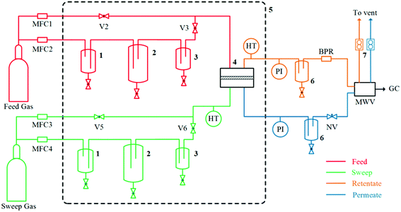
A desired amount of Nafion solution was mixed with a calculated amount of [Bmim][BF4] in a glass vial and subjected to magnetic stirring for at least 30 min. The solution was then poured into a glass Petri dish and heated to 80 °C for 100–120 min to generate uniform and un-cracked membranes.32 (Heating was required to ensure the generation of uniformly homogeneous films.) A second glass Petri dish was used to cover the first one to reduce the rate of solvent evaporation. After the solvent evaporated, the resulting membrane was dried under vacuum at 60 °C for at least 6 h prior to testing. Membrane thicknesses were measured with a Digimatic ID-H thickness gauge (Mituyoto, Aurora, IL) as the average of at least 10 measurements over the entire permeating area. The IL content (ωIL, wt%) in each hybrid membrane was calculated from | (1) |
2.3 Membrane characterization
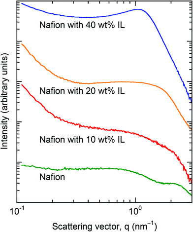
The thermal stability of the Nafion/IL membranes was investigated by thermogravimetric analysis (TGA) performed on a TA Q500 instrument. Samples weighing 5–10 mg were placed in sample pans and heated from ambient temperature to 550 °C at a heating rate of 10 °C min−1. To prevent premature degradation, nitrogen was used as an inert sweep gas at a flow rate of 60 mL min−1. Fourier-transform infrared (FTIR) spectroscopy was performed on a Thermo Nicolet Nexus spectrometer with a smart endurance reflection cell. All spectra were recorded in attenuated total reflectance (ATR) mode with a diamond crystal. This chemical analysis was conducted on neat [Bmim][BF4], neat Nafion and Nafion/IL hybrid membranes at various IL concentrations to discern if the two constituents interact chemically and, if so, which functionalities were involved. Spectra were averaged over 16 scans at a wavenumber resolution of 4 cm−1. The nanostructures of neat Nafion and several Nafion/IL membranes were characterized by small-angle X-ray scattering (SAXS) performed on beam-line 12-ID-B in the Advanced Photon Source at Argonne National Laboratory. The sample-to-detector distance and beam spot size were 2 m and 0.5 × 0.025 mm2, respectively, and samples were exposed to a 14 keV beam (with a wavelength, λ, of 0.087 nm). Data collected on a 2-D Pilatus 2 M detector were azimuthally integrated to yield scattering profiles in which intensity is expressed as a function of scattering vector (q), where q = (4π/λ)sin![[thin space (1/6-em)]](https://www.rsc.org/images/entities/char_2009.gif) θ and θ is half the scattering angle.
θ and θ is half the scattering angle.
The water uptake of various membranes was measured by placing the samples in a closed volume saturated with water vapor at ambient temperature and atmospheric pressure, followed by weighing at various times after initial exposure. The sample weight was recorded until a constant value was obtained, ensuring that equilibrium was reached. Values of water uptake (ΩH2O, expressed in terms of gH2O/gS, where gS refers to the overall mass of the dry sample) were computed from
 | (2) |
 achieved when permeation reached steady state according to
 | (3) |
 | (4) |
The permeability coefficient (Pi) of the ith penetrant species was measured by
 | (5) |
 was applied for mixed-gas permeation tests. It is worth mentioning that, while the ideal selectivity
  was also determined here, variation between ideal selectivity and separation factor was less than 5%, in which case only the separation factor is reported. Because of measurement differences in the permeation setups, specimens for single-gas permeation tests ranged in thickness from 50 to 75 μm, whereas film thicknesses were reduced to 15–25 μm for mixed-gas permeation tests.
3. Results and discussion
3.1 Characterization of neat Nafion membranes
Neat Nafion membranes can be fabricated via solvent casting or extrusion. In the present work, the first procedure is followed to prepare pure Nafion and hybrid Nafion/IL membranes. To ensure a suitable benchmark, we begin with an assessment of pure Nafion membranes by comparing cast membranes with commercially available extruded film in terms of transport properties. Doing so also permits direct comparison with previously reported data, since the gas transport properties under humid conditions have only been reported for extruded Nafion.22 Results obtained from mixed-gas tests are displayed in Fig. 2. As expected, CO2 permeability in the Nafion membrane increases with increasing RH to a significant extent (>100-fold enhancement). In addition, our results obtained for extruded Nafion are in favorable agreement with literature values.22 Differences in feed conditions (e.g., the CO2 partial pressure on the feed side of the membrane is 0.2 bar in our experiments but 2.0 bar in ref. 22) have a negligible effect on transport properties, as no swelling or relaxation phenomena are expected in this CO2 pressure range. Similar conclusions can be also drawn for the CO2/N2 selectivity, as the results obtained from our experiments are in the same range as the ones reported elsewhere.22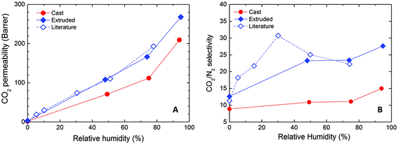 | ||
| Fig. 2 (A) CO2 permeability and (B) CO2/N2 selectivity as functions of RH for Nafion membranes obtained by solvent casting and extrusion. The literature data are obtained from ref. 22. | ||
As can be seen from Fig. 2, the membrane fabrication procedure clearly influences the apparent transport properties, since solvent-cast Nafion possesses a noticeably lower (25–35%) CO2 permeability compared to that of the extruded film over the entire RH range. Similar reductions (by about 50%) are also obtained for the separation factor. We propose that the two fabrication methods produce different nanostructures within the Nafion membranes, which result in different molecular transport properties. While exploration of the mechanism underpinning this observation warrants further study, it is beyond the scope of the current work. Moreover, insufficient information regarding the extrusion conditions for commercial Nafion severely limits the feasibility of further study. Therefore, the present study will focus exclusively on solvent-cast Nafion membranes and all further reference to Nafion will hereafter pertain to these membranes.
3.2 Ionic liquid selection
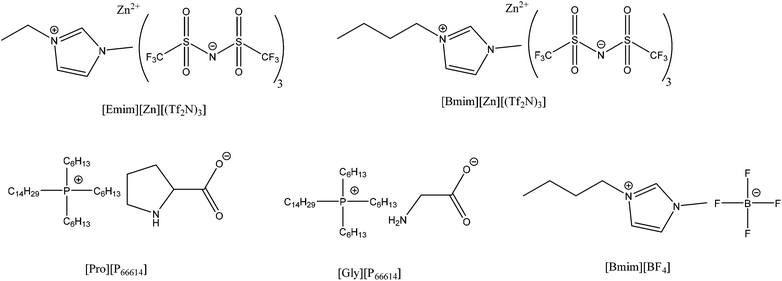
According to the two-pronged strategy adopted in the present work, ILs serve as the “first promoter” to enhance the permeability of gases in Nafion membranes. The initial selection of ILs in the fabrication of these hybrid membranes relies on the chemisorption of ILs with specific CO2 reactivity, as they are expected to provide higher CO2 selectivity and CO2 sorptive capacity. Specifically, 1-ethyl-3-methylimidazolium bis(trifluoromethanesulfonyl) imide ([Emim][Zn][(Tf2N)3])36 and 1-butyl-3-methylimidazolium bis(trifluoromethanesulfonyl) imide ([Bmim][Zn][(Tf2N)3]) containing Zn2+, as well as trihexyl(tetradecyl)phosphonium prolinate ([Pro][P66614]) and glycinate ([Gly][P66614]),37 have been synthesized and mixed with the starting Nafion solution. The chemical structures of these ILs considered in the present study are included in Fig. 3. Unfortunately, we have had no success in fabricating an acceptable membrane with most of these ILs, likely due to the strong interactions between the sulfonic acid groups present on Nafion and the basic moieties in the ILs. Such interactions induce visible macrophase separation, thus impeding the formation of a homogeneous membrane. As a consequence of this explanation, a physisorption-based IL is believed to be more likely to succeed because it possesses no reactive groups that can interact with the polymer during membrane preparation. In this vein and among the various IL options available, [Bmim][BF4] is found to yield satisfactory membranes and is remarkably suitable for the present investigation on the basis of its high CO2 solubility, CO2 diffusivity and CO2/N2 selectivity.38 Another benefit of this IL is that addition of a small concentration of water to [Bmim][BF4] has been reported39 to promote a significant drop in viscosity (∼50%), which might serve to enhance the diffusion coefficient of small molecules. For the above reasons, visually homogeneous, self-standing Nafion/[Bmim][BF4] membranes are only considered further in this study.3.3 Physical and chemical characterization
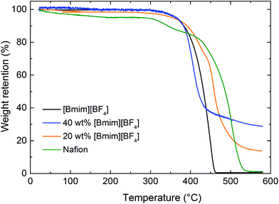
For both Nafion/IL composite membranes investigated by TGA, specimen mass losses are nearly negligible at temperatures below 350 °C. This result suggests that interactions occur between the IL, sulfonic acid groups and H2O molecules, in which case any residual water in the Nafion matrix becomes undetectable, and the thermal stability of the hybrid membranes is improved. As expected for many organic compounds, the mass loss for pure [Bmim][BF4] and Nafion is nearly 100% over 600 °C, implying that most of the materials decompose to gaseous products at these elevated temperatures. In the case of the Nafion/IL hybrid membranes, however, considerable residual mass remains detectable at the same temperature and appears to be directly related to the IL content in the membrane. One explanation for this unexpected outcome regarding the Nafion/IL membranes relates to the formation of new ion pairs between the IL and sulfonic acid groups in Nafion matrix. These ion pairs could stabilize C–S bonds and gradually enhance thermal stability,45 thereby providing an attractive materials design paradigm for high-temperature applications. Another possible explanation for our observation is that the side chains in Nafion might chemically react with [Bmim][BF4] at high temperatures and form a more stable chemical compound that pyrolyzes to carbon instead of vaporizing at temperatures in the vicinity of 600 °C.
Haubold et al.54 propose a sandwich model to analyze their SAXS results. The components of this model include a highly incompatible fluorocarbon phase, an interphase wherein the sulfonic acid groups reside and a solution regime in the presence of a polar solvent. In their study, they examine the nanostructure of Nafion in the presence of water/methanol cosolvents. Recent cryo-transmission electron microtomography images55 indicate, however, that a sandwich representation might constitute an oversimplification of the Nafion nanostructure especially at low q. Even without application of the scattering model developed by Haubold et al.,54 their SAXS results of Nafion in the presence of water and pure methanol are nonetheless useful for comparison with our data collected from Nafion/IL membranes. In the cases of water and methanol, scattering is observed to increase slightly beyond that of neat Nafion at low q, but the ionic peak remains clearly unobstructed. This trend is not evident in Fig. 6, suggesting that the addition of IL induces a composition-dependent rearrangement of the Nafion nanostructure rather than simply inducing swelling. Although detailed morphological analysis of Nafion/IL membranes by electron microscopy or microtomography would likely elucidate IL-induced morphological alteration, such characterization is beyond the scope of the present work.
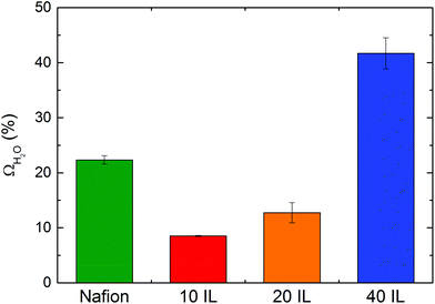 | ||
| Fig. 7 Water uptake of Nafion and Nafion/IL membranes at atmospheric temperature and pressure and 100% RH (10 IL = 10 wt% [Bmim][BF4], 20 IL = 20 wt% [Bmim][BF4], 40 IL = 40 wt% [Bmim][BF4]). | ||
It is well accepted that the highly hydrophilic sulfonic acid anions in Nafion can form dispersed ionic clusters with diameters of ≈1.5 nm throughout the Nafion matrix.57,58 These ionic clusters play an important role in localized hydration and, thus, water uptake. When the [Bmim][BF4] is added to the polymeric matrix at low concentrations, however, new ion pairs are likely to form due to the strong ion-ion interaction between sulfonic acid and the IL and this could promote a nontrivial change in both the population and composition of the ionic clusters. Such variation is expected to have a negative impact on water uptake since the ions become bound together to yield a neutral charge. As the concentration of IL is increased in the Nafion/IL membranes, the distribution of IL is more uniform throughout the material (as evidenced by SAXS in Fig. 6), resulting in unbound (free) IL that, due to the hydrophilic nature of [Bmim][BF4], ensures enhanced water uptake in Nafion/IL membranes at high IL concentrations.
3.4 Single- and mixed-gas permeation studies
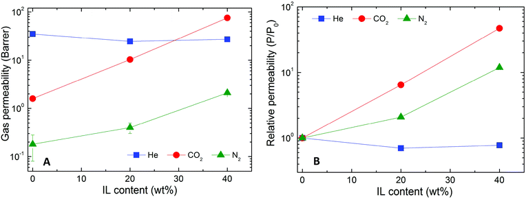 | ||
| Fig. 8 Permeability (A) and relative permeability (B) of several gases (color-coded) in Nafion/IL membranes containing different IL concentrations at ambient temperature and 2.0 bar. | ||
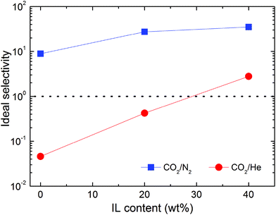 | ||
| Fig. 9 Ideal selectivity of two gas pairs (color-coded) in Nafion/IL membranes containing different IL concentrations at ambient temperature and 2.0 bar. | ||
Interestingly, addition of IL to Nafion has limited impact on He gas transport. In fact, He permeability decreases in the hybrid membranes, regardless of the amount of IL contained in the matrix. For this reason, the neat Nafion membrane can be considered He-selective (CO2/He selectivity of 0.046), while the hybrid membrane with 40 wt% [Bmim][BF4] becomes CO2-selective, as indicated in Fig. 9, with a selectivity of 2.7. A possible explanation for this observed phenomenon relates to the influence of gas solubility, which is markedly larger in the hybrid membranes compared to neat Nafion. In this scenario, the permeability of gases in the hybrid membranes is anticipated to increase considerably with increasing condensability so that highly condensable gases (e.g., CO2) are more profoundly affected than less condensable ones (e.g., N2 and He).
 | (6) |
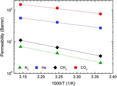 | ||
| Fig. 10 Permeability of several gases (color-coded) as a function of temperature in the Nafion/IL membrane with 40 wt% [Bmim][BF4] at 2.0 bar. | ||
| Permeability (Barrer) | |||
|---|---|---|---|
| 25 °C | 35 °C | 45 °C | |
| CO2 | 75.4 | 115.1 | 148.9 |
| He | 27.1 | 41.0 | 55.8 |
| N2 | 2.1 | 4.3 | 6.9 |
| CH4 | 3.5 | 6.6 | 11.2 |
| CO2 | N2 | CH4 | He | |
|---|---|---|---|---|
| E P (kJ mol−1) | 25.6 | 44.0 | 42.9 | 27.0 |
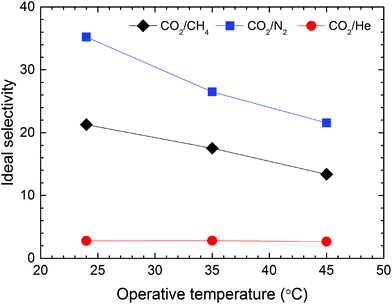
Fig. 11 displays the effect of temperature on the ideal gas selectivities αCO2/N2, αCO2/CH4 and αCO2/He at 2.0 bar. As anticipated from the larger values of EP for N2 and CH4 relative to that of CO2, both αCO2/N2 and αCO2/CH4 decrease significantly when temperature is increased from 25 to 45 °C. This observation reflects a corresponding reduction in solubility selectivity due to the sharp temperature-driven decrease of CO2 solubility in [Bmim][BF4]. Concurrently, the diffusivity of gases possessing a larger kinetic diameter (e.g., N2 and CH4) is more noticeably influenced by the increase in operating temperature relative to smaller penetrants (e.g., CO2), which also negatively affects membrane selectivity.62
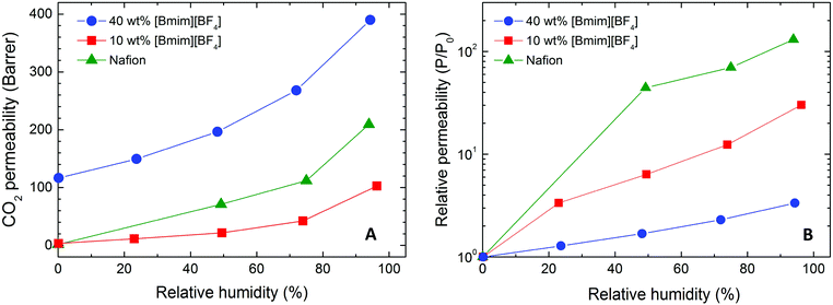 | ||
| Fig. 12 CO2 permeability (A) and relative CO2 permeability (B) of Nafion/IL membranes varying in composition (color-coded) as a function of RH at ambient temperature and 2.0 bar. | ||
According to Sarti and co-workers,22 water-induced enhancement of gas transport in neat Nafion can be traced to different nanoscale morphologies of the membrane. Under dry conditions the ionic clusters formed by sulfonic acid moieties behave as impermeable obstacles for gas diffusion. Upon hydration, nanoscale water channels form and serve as preferential diffusive pathways for the permeation of gas molecules. The solubility of gas penetrants in water therefore plays an important role in determining the effect of water on the permeability coefficient for a specific penetrant. In the case of Nafion/IL hybrid membranes, interactions between the IL moieties and the sulfonic acid groups of Nafion occur in similar fashion as water, as evidenced by the water uptake results in Fig. 7. At sufficiently high concentrations, the IL molecules are expected to form interconnected nanochannels that function as diffusive pathways for gas transport. Similarly, gas solubility in ILs likewise governs membrane selectivity.
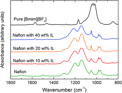
On the basis of the results obtained for the CO2 permeability at different RH values, the dependence of the relative CO2 permeability on RH is shown in Fig. 12B. While water vapor appears very effective at promoting CO2 permeability in neat Nafion (with a 130× increase), an increase in IL content in hybrid Nafion/IL membranes is accompanied by a less pronounced positive effect: 30× and 3× for hybrid membranes containing 10 and 40 wt% [Bmim][BF4], respectively. As alluded to earlier, this phenomenon implies that water vapor can effectively increase the size of the ionic clusters in the polymeric matrix, thus greatly improving CO2 permeability in neat Nafion membranes. In the Nafion/IL membranes, however, IL molecules interfere with the ionic clusters composed of sulfonic acid groups, according to the FTIR results provided in Fig. 5, and reduce their ionic strength, which, in turn, enhances CO2 diffusivity through the hybrid membrane matrix. Because of this IL-induced interaction, the effect of water is partially replaced, thereby diminishing the relative influence of water vapor on CO2 permeability observed in Fig. 12B. Furthermore, under humid conditions, the IL itself is affected by the presence of water, which is expected to promote reductions in both CO2 solubility and viscosity and a corresponding increase in the diffusion of gaseous penetrants. Although no direct evidence is presently available for [Bmim][BF4], independent studies of similar ILs verify that the first effect is somewhat limited (<15% drop in CO2 absorptive capacity63), whereas the change in viscosity (a 45–75% decrease at ambient temperature64) is expected to enhance the diffusion coefficient to a larger extent.65 Therefore, the enhanced CO2 permeability due to humidity in the Nafion/IL hybrid membranes visible in Fig. 12A at 40 wt% [Bmim][BF4] is attributed, at least in part, to higher CO2 diffusivity within the IL.
The ideal CO2/N2 selectivity (separation factor) of Nafion/IL membranes prepared at various IL concentrations and measured at different RH conditions is displayed in Fig. 13. As discussed in regard to Fig. 8, the CO2/N2 selectivity of these hybrid membranes increases with increasing IL content under dry gas feed conditions. The mixed-gas selectivity of the hybrid membrane appears slightly lower compared to the one discerned from single-gas permeation tests, most likely due to the lower partial pressure of CO2 in the feed gas. Interestingly, an increase in RH in the gas feed manifests a different effect on the CO2/N2 selectivity of the hybrid membranes. In the Nafion/IL membrane with 40 wt% [Bmim][BF4], the separation factor (∼30) is close to the CO2/N2 separation factor obtained from [Bmim][BF4]-based SILMs,66 indicating that the IL dominates the separation mechanism in the membrane. For neat Nafion and the Nafion/IL membrane with 10 wt% [Bmim][BF4], the CO2/N2 selectivity is much lower under dry conditions and increases systematically with increasing RH. On the basis of these observations, we believe that, in the dry state or low RH levels, gas selectivity is determined by the Nafion matrix, while at higher RH values, selectivity is determined primarily by water absorbed in the ionic clusters.22
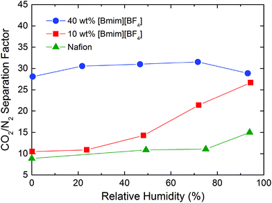 | ||
| Fig. 13 CO2/N2 selectivity in Nafion/IL membranes containing different IL concentrations (color-coded) obtained from mixed-gas permeation tests as a function of RH at ambient temperature and 2.0 bar. | ||
By analyzing the membrane composition at different IL loading levels under the dry and humidified conditions reported in Table 3, we can identify the different contributions of the IL and water on membrane transport properties. Addition of IL only to Nafion promotes a limited interaction with the sulfonic groups present on the polymer chain (up to 3.2 molIL/molSO3), thereby confirming a positive effect on both CO2 permeability and selectivity of the membrane. Stronger influence on CO2 permeability is, however, observed in the presence of H2O, due presumably to the larger population of H2O molecules able to interact with the ionic moieties (up to 41.7 molH2O/molSO3). On one hand, if we now consider a comparable concentration (∼20 wt%) of IL and H2O in the polymer matrix (i.e., Nafion + 20 wt% [Bmim][BF4] under dry conditions and cast Nafion under fully humidified conditions), H2O appears to be much more effective at enhancing CO2 permeability (209 versus 10 Barrer). On the other hand, the presence of the IL ensures a higher selectivity (27 versus 14). Thus, when both IL and water are present in the Nafion matrix, the CO2 permeability is significantly less sensitive to water content, whereas membrane selectivity increases with increasing IL content, which together illustrate the synergetic effect of IL and H2O in enhancing the overall transport properties of Nafion.
| Nafion (wt%) | [Bmim][BF4] (wt%) | H2O (wt%) | [Bmim][BF4] (mol/molSO3) | H2O (mol/molSO3) | P CO2 (Barrer) | α CO2/N2 |
|---|---|---|---|---|---|---|
| 1.00 | 0.00 | 0.00 | 0.0 | 0.0 | 1.6 | 9 |
| 0.90 | 0.10 | 0.00 | 0.5 | 0.0 | 3.4 | 11 |
| 0.80 | 0.20 | 0.00 | 1.2 | 0.0 | 10 | 27 |
| 0.60 | 0.40 | 0.00 | 3.2 | 0.0 | 116 | 28 |
| 0.81 | 0.00 | 0.19 | 0.0 | 14.0 | 209 | 14 |
| 0.83 | 0.09 | 0.07 | 0.5 | 5.4 | 102 | 26 |
| 0.43 | 0.28 | 0.29 | 3.2 | 41.7 | 329 | 28 |
The separation performance of Nafion/IL membranes developed in this study is compared in Table 4 with other perfluorosulfonated membranes and polymer/IL membranes reported in the literature. Moreover, results obtained here are compared with other separation membranes in the Robeson plot71 provided in Fig. 14. In this figure, neat Nafion membranes exhibit relatively poor gas-transport properties in the dry state, as evidenced by CO2 permeabilities of ∼2 Barrer and CO2/N2 selectivities of 8–10. Addition of the “first promoter” ([Bmim][BF4]) significantly improves the transport properties. Simultaneous enhancement of CO2 permeability and CO2/N2 selectivity in the membrane with 40 wt% [Bmim][BF4] brings the separation performance closer to the Robeson upper bound.71,72 When the “second promoter” (water vapor) is added to the system, both the CO2 permeability and CO2/N2 selectivity improve significantly for the Nafion/IL hybrid membrane with 10 wt% [Bmim][BF4]. In the hybrid membrane with 40 wt% [Bmim][BF4], the CO2 permeability displays a monotonic increase with increasing RH, while the separation factor remains relatively constant, which allows the separation performance to approach the upper bound. The separation attributes of the membrane containing 40 wt% [Bmim][BF4] are also higher than those of the extruded membranes, thereby confirming that post-combustion CO2 capture membranes can be fabricated with relatively good performance metrics. The results reported in this work reveal that synergy exists between both promoters, suggesting that Nafion membranes can be more fully optimized with regard to their molecular transport properties for CO2 separation.
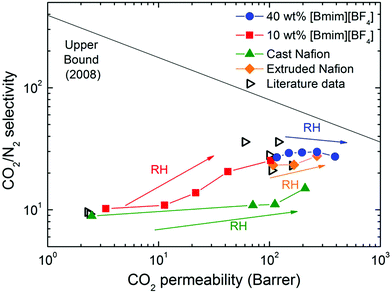 | ||
| Fig. 14 Robeson plot@ for the CO2/N2 separation performance obtained from mixed-gas permeation tests of Nafion/IL membranes varying in composition (color-coded). Diamonds are literature data from Table 4. | ||
| Membrane | P CO2 (Barrer) | α CO2/N2 | Ref. |
|---|---|---|---|
| a Single-gas permeation test conducted with a feed pressure of 1 atm at 25 °C. b Single-gas permeation test conducted with a feed pressure of 2 atm at 35 °C. c Single-gas permeation test conducted with a feed pressure of 1 atm 35 °C. d Mixed-gas permeation test conducted with a CO2 partial pressure of 199 kPa at ambient temperature. e Single-gas permeation test conducted with a feed pressure of 2 bar at 25 °C, gas permeability data estimated from Fig. 4 and 7 in ref. 19. f Single-gas permeation test conducted with a feed pressure of 2 bar at ambient temperature. g Single-gas permeation test conducted with a feed pressure of 2 bar at ambient temperature. h CO2/N2 mixed-gas (10/90 vol%) permeation test conducted with a feed pressure of 2 bar at ambient temperature. | |||
| Nafion 111 (dry state) | 2.3 | — | 67 |
| Nafion 111 (100% RH) | 257 | — | 67 |
| Nafion 117 (dry) | 2.3 | 9.6 | 57 |
| Nafion 117 (dry) | 2.4 | 9.2 | 20 |
| Nafion 112-K (wet) | 51.3 | — | 68 |
| Nafion 112-EDA (wet) | 104 | — | 68 |
| Nafion 117 (75% RH) | 160 | 23 | 22 |
| Aquivion (75% RH) | 120 | 36 | 22 |
| Epoxy–amine poly(ionic liquid) (PIL)/IL | 100 | 28 | 10 |
| PIL/[C2mim][Tf2N] | 60 | 36 | 69 |
| PIL/IL | 105 | 21 | 70 |
| Nafion (cast, dry) | 1.6 | 8.9 | This workg |
| Nafion + 40 wt% [Bmim][BF4] (dry) | 75.4 | 35.2 | This workg |
| Nafion (cast, 100% RH) | 209 | 15.0 | This workh |
| Nafion + 40 wt% [Bmim][BF4] (100% RH) | 390 | 29.9 | This workh |
4. Conclusions
In the present study, Nafion/IL hybrid membranes containing different IL concentrations have been prepared by physically mixing Nafion solutions with [Bmim][BF4]. The resultant membranes have been physically and chemically characterized, evincing favorable thermal and chemical properties as well as enhanced CO2 separation performance. While adding 40 wt% [Bmim][BF4] to Nafion yields a CO2 permeability increase from 1.6 to 75.4 Barrer, the presence of water can further increase the CO2 permeability to 390 Barrer, which constitutes a 200× enhancement compared to neat Nafion. On the basis of the results reported here, we propose that [Bmim][BF4] in the Nafion/IL hybrid membranes functions as a “first promoter” to improve gas transport for most of the tested species, especially CO2. Water vapor introduced in the Nafion and Nafion/IL membranes further improve gas permeability as a “second promoter”. As the RH increases from 0 to 100%, the CO2 permeability of the hybrid Nafion/IL membranes increases from 116 to 390 Barrer with no change in CO2/N2 selectivity (∼30). These observations confirm that synergy exists between the IL and water vapor within the Nafion matrix. The possibility to exploit polyelectrolyte solvent casting as a route to thin separation membranes, without paying a penalty in terms of separation performance, opens new opportunities for the fabrication of Nafion-based CO2 capture membranes. Judicious incorporation of ILs possessing higher CO2 solubility and diffusivity into solvent-cast Nafion (by chemisorption of ILs or by preparing blends of chemisorption-/physisorption-introduced ILs), combined with humidified gas streams, might further enhance membrane separation performance. In this regard, a detailed molecular-level investigation of the interactions between hydrated Nafion and ionic additives is clearly warranted.Conflicts of interest
There are no conflicts to declare.Acknowledgements
This work was supported at NTNU by the European Union Seventh Framework Programme (FP7/2007–2013) in the HiPerCap project under grant agreement no.608555. We also thank the Nonwovens Institute at North Carolina State University for financial support and Dr B. Lee of the Advanced Photon Source at Argonne National Laboratory for technical assistance. This research used resources of the Advanced Photon Source, a U.S. Department of Energy (DOE) Office of Science User Facility operated for the DOE Office of Science by Argonne National Laboratory under Contract No. DE-AC02-06CH11357.References
- X. Zhang, X. Zhang, H. Dong, Z. Zhao, S. Zhang and Y. Huang, Energy Environ. Sci., 2012, 5, 6668–6681 CAS
.
- J. Wang, J. Luo, S. Feng, H. Li, Y. Wan and X. Zhang, Green Energy Environ., 2016, 1, 43–61 CrossRef
.
- P. Li, D. R. Paul and T.-S. Chung, Green Chem., 2012, 14, 1052–1063 RSC
.
- D. L. Gin and R. D. Noble, Science, 2011, 332, 674–676 CrossRef CAS PubMed
.
- Z. Dai, L. Ansaloni and L. Deng, Ind. Eng. Chem. Res., 2016, 55, 5983–5992 CrossRef CAS
.
- Z. D. Dai, R. D. Noble, D. L. Gin, X. P. Zhang and L. Y. Deng, J. Membr. Sci., 2016, 497, 1–20 CrossRef CAS
.
- J. Deng, L. Bai, S. Zeng, X. Zhang, Y. Nie, L. Deng and S. Zhang, RSC Adv., 2016, 6, 45184–45192 RSC
.
- Z. Dai, L. Bai, K. N. Hval, X. Zhang, S. Zhang and L. Deng, Sci. China: Chem., 2016, 59, 538–546 CrossRef CAS
.
- S. Raeissi and C. J. Peters, Green Chem., 2009, 11, 185–192 RSC
.
- W. M. McDanel, M. G. Cowan, J. A. Barton, D. L. Gin and R. D. Noble, Ind. Eng. Chem. Res., 2015, 54, 4396–4406 CrossRef CAS
.
- F. Moghadam, E. Kamio and H. Matsuyama, J. Membr. Sci., 2017, 525, 290–297 CrossRef CAS
.
- K. Friess, J. C. Jansen, F. Bazzarelli, P. Izak, V. Jarmarova, M. Kacirkova, J. Schauer, G. Clarizia and P. Bernardo, J. Membr. Sci., 2012, 415, 801–809 CrossRef
.
- Y. Y. Gu, E. L. Cussler and T. P. Lodge, J. Membr. Sci., 2012, 423, 20–26 CrossRef
.
- T. P. Lodge, Science, 2008, 321, 50–51 CrossRef CAS PubMed
.
- J. Y. Yuan, D. Mecerreyes and M. Antonietti, Prog. Polym. Sci., 2013, 38, 1009–1036 CrossRef CAS
.
- L. Ansaloni, Z. Dai, J. J. Ryan, K. P. Mineart, Q. Yu, K. T. Saud, M.-B. Hägg, R. J. Spontak and L. Deng, Adv. Mater. Interfaces, 2017, 1700854 CrossRef
.
- L. Olivieri, H. Aboukeila, M. Giacinti Baschetti, D. Pizzi, L. Merlo and G. C. Sarti, J. Membr. Sci., 2017, 542, 367–377 CrossRef CAS
.
- Y. Wang, K. S. Chen, J. Mishler, S. C. Cho and X. C. Adroher, Appl. Energy, 2011, 88, 981–1007 CrossRef CAS
.
- C. HeitnerWirguin, J. Membr. Sci., 1996, 120, 1–33 CrossRef CAS
.
- J. S. Chiou and D. R. Paul, Ind. Eng. Chem. Res., 1988, 27, 2161–2164 CrossRef CAS
.
- Y. F. Fan, D. Tongren and C. J. Cornelius, Eur. Polym. J., 2014, 50, 271–278 CrossRef CAS
.
- M. Giacinti Baschetti, M. Minelli, J. Catalano and G. C. Sarti, Int. J. Hydrogen Energy, 2013, 38, 11973–11982 CrossRef CAS
.
- K. A. Mauritz and R. B. Moore, Chem. Rev., 2004, 104, 4535–4586 CrossRef CAS PubMed
.
- F. I. Allen, L. R. Comolli, A. Kusoglu, M. A. Modestino, A. M. Minor and A. Z. Weber, ACS Macro Lett., 2015, 4, 1–5 CrossRef CAS
.
- A. Kusoglu and A. Z. Weber, Chem. Rev., 2017, 117, 987–1104 CrossRef CAS PubMed
.
- K. Schmidt-Rohr and Q. Chen, Nat. Mater., 2008, 7, 75–83 CrossRef CAS PubMed
.
- S. Yoo, J. Won, S. W. Kang, Y. S. Kang and S. Nagase, J. Membr. Sci., 2010, 363, 72–79 CrossRef CAS
.
- D. Sun and J. Zhou, AIChE J., 2013, 59, 2630–2639 CrossRef CAS
.
- K. Broka and P. Ekdunge, J. Appl. Electrochem., 1997, 27, 117–123 CrossRef CAS
.
- H. Matsuyama, K. Matsui, Y. Kitamura, T. Maki and M. Teramoto, Sep. Purif. Technol., 1999, 17, 235–241 CrossRef CAS
.
- H. L. Yeager and A. Steck, J. Electrochem. Soc., 1981, 128, 1880–1884 CrossRef CAS
.
- Y. Wang, H. Chen, Y. Wang, B. Luo, L. Chang, Z. Zhu and B. Li, Polym. Eng. Sci., 2014, 54, 818–830 CAS
.
- D. G. Pye, H. H. Hoehn and M. Panar, J. Appl. Polym. Sci., 1976, 20, 1921–1931 CrossRef CAS
.
- Z. Dai, L. Ansaloni, D. L. Gin, R. D. Noble and L. Deng, J. Membr. Sci., 2017, 523, 551–560 CrossRef CAS
.
- Z. Dai and L. Deng, Int. J. Greenhouse Gas Control, 2016, 54(Part 1), 59–69 CrossRef CAS
.
- H. Liu, J. Huang and P. Pendleton, Energy Procedia, 2011, 4, 59–66 CrossRef CAS
.
- B. E. Gurkan, J. C. de la Fuente, E. M. Mindrup, L. E. Ficke, B. F. Goodrich, E. A. Price, W. F. Schneider and J. F. Brennecke, J. Am. Chem. Soc., 2010, 132, 2116–2117 CrossRef CAS PubMed
.
- Z. Lei, C. Dai and B. Chen, Chem. Rev., 2014, 114, 1289–1326 CrossRef CAS PubMed
.
- M. B. Shiflett and A. Yokozeki, Ind. Eng. Chem. Res., 2005, 44, 4453–4464 CrossRef CAS
.
- M. E. V. Valkenburg, R. L. Vaughn, M. Williams and J. S. Wilkes, Thermochim. Acta, 2005, 425, 181–188 CrossRef
.
- Y. Wang, Y. Kawano, S. R. Aubuchon and R. A. Palmer, Macromolecules, 2003, 36, 1138–1146 CrossRef CAS
.
- S. H. de Almeida and Y. Kawano, J. Therm. Anal. Calorim., 1999, 58, 569–577 CrossRef CAS
.
- Q. Deng, C. A. Wilkie, R. B. Moore and K. A. Mauritz, Polymer, 1998, 39, 5961–5972 CrossRef CAS
.
- L. G. Lage, P. G. Delgado and Y. Kawano, J. Therm. Anal. Calorim., 2004, 75, 521–530 CrossRef CAS
.
- Y. Iwai and T. Yamanishi, Polym. Degrad. Stab., 2009, 94, 679–687 CrossRef CAS
.
- K. Ataka and M. Osawa, Langmuir, 1998, 14, 951–959 CrossRef CAS
.
- J. Schiffer and D. F. Hornig, J. Chem. Phys., 1968, 49, 4150–4160 CrossRef CAS
.
- Shalu, S. K. Chaurasia, R. K. Singh and S. Chandra, J. Phys. Chem. B, 2013, 117, 897–906 CrossRef CAS PubMed
.
- M. Laporta, M. Pegoraro and L. Zanderighi, Phys. Chem. Chem. Phys., 1999, 1, 4619–4628 RSC
.
- J. Ostrowska and A. Narebska, Colloid Polym. Sci., 1984, 262, 305–310 CAS
.
- W. Kujawski, Q. T. Nguyen and J. Néel, J. Appl. Polym. Sci., 1992, 44, 951–958 CrossRef CAS
.
- N. Nanbu, Y. Sasaki and F. Kitamura, Electrochem. Commun., 2003, 5, 383–387 CrossRef CAS
.
- J. P. Wu, M. J. Wang and J. P. W. Stark, J. Quant. Spectrosc. Radiat. Transfer, 2006, 102, 228–235 CrossRef CAS
.
- H. G. Haubold, T. Vad, H. Jungbluth and P. Hiller, Electrochim. Acta, 2001, 46, 1559–1563 CrossRef CAS
.
- F. I. Allen, L. R. Comolli, A. Kusoglu, M. A. Modestino, A. M. Minor and A. Z. Weber, ACS Macro Lett., 2015, 4, 1–5 CrossRef CAS
.
- J. Catalano, T. Myezwa, M. G. De Angelis, M. G. Baschetti and G. C. Sarti, Int. J. Hydrogen Energy, 2012, 37, 6308–6316 CrossRef CAS
.
- M. Mukaddam, E. Litwiller and I. Pinnau, Macromolecules, 2016, 49, 280–286 CrossRef CAS
.
- K. A. Mauritz and R. B. Moore, Chem. Rev., 2004, 104, 4535–4585 CrossRef CAS PubMed
.
- R. M. Barrer and G. Skirrow, J. Polym. Sci., 1948, 3, 549–563 CrossRef CAS
.
- J. H. Kim, S. Y. Ha and Y. M. Lee, J. Membr. Sci., 2001, 190, 179–193 CrossRef CAS
.
- N. P. Patel, A. C. Miller and R. J. Spontak, Adv. Funct. Mater., 2004, 14, 699–707 CrossRef CAS
.
- L. Ansaloni, J. R. Nykaza, Y. Ye, Y. A. Elabd and M. Giacinti Baschetti, J. Membr. Sci., 2015, 487, 199–208 CrossRef CAS
.
- D. Fu, X. Sun, J. Pu and S. Zhao, J. Chem. Eng. Data, 2006, 51, 371–375 CrossRef CAS
.
- J. Jacquemin, P. Husson, A. A. H. Padua and V. Majer, Green Chem., 2006, 8, 172–180 RSC
.
- P. Feron and A. Jansen, Sep. Purif. Technol., 2002, 27, 231–242 CrossRef CAS
.
- L. A. Neves, N. Nemestóthy, V. D. Alves, P. Cserjési, K. Bélafi-Bakó and I. M. Coelhoso, Desalination, 2009, 240, 311–315 CrossRef CAS
.
- S. A. Ma, M. Odgaard and E. Skou, Solid State Ionics, 2005, 176, 2923–2927 CrossRef CAS
.
- J. Pellegrino and Y. S. Kang, J. Membr. Sci., 1995, 99, 163–174 CrossRef CAS
.
- J. E. Bara, D. L. Gin and R. D. Noble, Ind. Eng. Chem. Res., 2008, 47, 9919–9924 CrossRef CAS
.
- T. K. Carlisle, E. F. Wiesenauer, G. D. Nicodemus, D. L. Gin and R. D. Noble, Ind. Eng. Chem. Res., 2013, 52, 1023–1032 CrossRef CAS
.
- L. M. Robeson, J. Membr. Sci., 2008, 320, 390–400 CrossRef CAS
.
- H. B. Park, J. Kamcev, L. M. Robeson, M. Elimelech and B. D. Freeman, Science, 2017, 356, eaab0530 CrossRef PubMed
.
Footnote |
| † These authors contributed equally to this work. |
| This journal is © The Royal Society of Chemistry 2018 |

