 Open Access Article
Synthesis, structure and optoelectronic properties of hybrid iodobismuthate & iodoantimonate semiconducting materials†
Adam J.
Dennington
 and
Mark T.
Weller
 *
*
Department of Chemistry, University of Bath, BA2 7AY, UK. E-mail: M.T.Weller@bath.ac.uk
First published on 2nd February 2018
Abstract
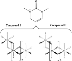
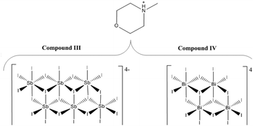
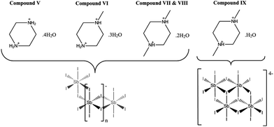
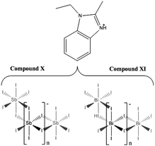
The syntheses and structures of five iodobismuthate and nine iodoantimonate hybrid materials are presented. The 1,3-dimethyl-2-oxo-2,3-dihydropyrimidinium cation has been used to template the isostructural, one-dimensional [C6H9N2O][SbI4] (I) and [C6H9N2O][BiI4] (II), while 4-methylmorpholinium templates the compounds, [C5H12NO]4[Sb6I22] (III) and [C5H12NO]4[Bi4I16] (IV), both containing isolated iodopnictogenide cluster anions. Five iodoantimonate compounds, templated by piperazinium cation derivatives, have been synthesised; [C4H12N2][SbI4]2·4H2O (V), [C5H14N2][SbI4]2·3H2O (VI), two polymorphs of [C6H16N2][SbI4]2·2H2O (VII and VIII) and [C6H16N2][Sb4I16]0.5·H2O (IX), mainly adopting structures closely related to previously published 1D iodobismuthate hybrid materials. 1-Ethyl-2-methylbenzimidazolium cations, formed in situ in the reaction medium, template the isostructural 1D structures of [C10H13N2][SbI4] (X) and [C10H13N2][BiI4] (XI). 1,4-Diazabicyclo[2.2.2]octandiium (DABCOH2)2+ di-cations are shown to template a hydrated iodoantimonate structure [C6H14N2]2[Sb4I16]·2H2O (XII) containing [Sb4I16]4− complex anions and a mixed phase of two iodobismuthate materials; one phase contains, uniquely, a mixture of the complex anions [Bi2I10]4− and [BiI6]3− in the form [C6H14N2]10[Bi2I10]2[BiI6]4·(H2O)8 (XIII), and the second, [C6H14N2]2[Bi4I16]·2H2O (XIV), contains discrete [Bi4I16]4− clusters. The stability and thermal decomposition routes of these phases have been determined using thermogravimetric analysis. UV-vis spectroscopy has been used to determine band gap energy estimates which are related, for a range of iodobismuthate and iodoantimonate materials, to their structural features and potential optoelectronic applications.
Introduction
The research field of haloantimonate(III) and halobismuthate(III) hybrid organic–inorganic materials has developed over the past few decades to yield materials of interest for their non-linear dielectric and optical properties. The use of different organic cation templating species has been found to yield a large variety of structures with controlled structural dimensionality of the anionic-unit, vide infra. Acting as counter-ions to the anionic iodopnictogenide unit within the structure, the organic species can additionally yield various polymorphs, often by variation of the exact reaction conditions.1–4Trivalent metal (M = Bi3+, Sb3+) hybrid halometallate materials, with general formula [Ra]n+[MbX3b+a]n− are currently known to adopt approximately 30 variants of the anionic moiety. The most prevalent species found are oligomeric and extending polymeric structures of conjoined [MX6] octahedra but more rarely monomeric [MX6] units have been reported.5 The ability to form [MX6] octahedra in metal–halide systems is a prerequisite to forming perovskites (corner-sharing), while adopting alternative non-perovskite structural units (edge-, face-sharing or in isolation) opens up a vast library of materials with a variety of anionic substructures. For example as demonstrated by iodobismuthate structures, the identity of the anionic inorganic component currently ranges from discrete 0D units (simple anions and clusters) in [BiI6]3− to [Bi8I30]6− motifs,6–21 through 1D chain structures,7,22–27 most commonly in [BiI4]n− or [BiI5]n2− compositions; just one 2D extended network has been reported, [Bi2/3I4]n2−.28 The identity of anionic component in these hybrid materials is dependent on many different factors including the templating species, synthesis conditions and technique as well as the molar ratios of reagents used. In a similar vein, for iodoantimonate materials the anionic component can take the form of discrete units with a range of compositions and associated charges, for example, [Sb3I11]2−, [Sb2I9]3−, [Sb5I18]3−, [Sb6I22]4−, [Sb8I28]4−![[thin space (1/6-em)]](https://www.rsc.org/images/entities/char_2009.gif) 5,29,30 as well as one-dimensional unit configurations [SbI4]n−,31,32 [SbI5]n−,23 [Sb2I7]n−,33 and [Sb3I10]n−.34 Iodometallate materials are principally of interest in comparison with their bromo- and chloro-metallate equivalents as they tend to possess smaller band gaps and lower carrier effective masses2,35 – important properties for high performance optoelectronic materials.
5,29,30 as well as one-dimensional unit configurations [SbI4]n−,31,32 [SbI5]n−,23 [Sb2I7]n−,33 and [Sb3I10]n−.34 Iodometallate materials are principally of interest in comparison with their bromo- and chloro-metallate equivalents as they tend to possess smaller band gaps and lower carrier effective masses2,35 – important properties for high performance optoelectronic materials.
Regarding the properties required of non-linear dielectrics, four anionic species have been identified in previous studies as having the potential to exhibit ferroelectric properties, R3M2X9,5 RMX4,36 RMX5,37 and R5M2X11;38,39 the vast majority of the compounds reported adopt the sub-lattice forms [M2X9]3− and [M2X11]5−. It is worth noting that for R3M2X9 four separate structural forms are known: (i) a two-dimensional layer structure, (ii) an infinite one-dimensional chain, (iii) discrete di-octahedral units, and (iv) discrete tetra-octahedral units; only the 2D layer structure form has been identified to demonstrate ferroelectric properties. Conversely, for [M2X11]5− the structural unit is exclusively discrete di-octahedral units with all salts exhibiting ferroelectric properties.
Also recently, and with rapidly growing traction in the last three years, hybrid organic–inorganic perovskite and perovskite-like materials have established themselves as the principal area of photovoltaic research. In particular, the leading absorber material in this field is the hybrid compound methylammonium lead iodide, MAPI, [CH3NH3][PbI3]; with the highest solar cell efficiencies utilising derivatives of this material reaching over 22%.40 However, a key concern of utilising this material for commercial applications is the presence of the toxic metal lead. Additional issues regarding the deployment of MAPI in solar cell devices concern its long-term stability; research aiming to combat this issue of instability when exposed to light (and/or) air is ongoing.41,42 Concurrently, other non-toxic, post transition metal-based, hybrid materials with similar functional optoelectronic properties are being explored as alternative candidates for photovoltaic applications. Such materials can offer the prospect of improved material stability, allowing simpler device processing and manufacture, and long-term cell deployment. As a result, we have been interested in exploring the synthesis, structural characterisation and studying the electrical properties of novel compounds of this type.
The desired semiconducting properties these materials have has been highlighted to stem from the fundamental electronic structure of the post transition metals demonstrating the “inert pair effect” with filled 5s2 or 6s2 orbitals; these orbitals have been shown to produce shallow defects and a dispersed valence band. Prospective metal cation candidates of interest in forming semiconducting metal–halide hybrid structures are considered to be Sn2+, Bi3+ and Sb3+. Initial isovalent substitution studies with Sn2+ replacing Pb2+ in hybrid perovskite related materials have proved to be largely unsuccessful for applications, as Sn2+ compounds have been shown to undergo rapid oxidation by air and decompose readily through reaction with moisture.43 Therefore the impetus has been to explore alternatives with potentially improved stability to degradation via oxidation.44
The stability of the Group (n-2) exhibiting the loan pair effect increases from Group 13 through Group 14 to Group 15. Thus while In+ and Tl+ are readily oxidised to the trivalent state and as mentioned previously Sn2+, and to a lesser extent Pb2+, can be easily oxidised, Sb3+ and, particularly, Bi3+ are both more difficult to oxidise to the Group oxidation state. This makes these species ideal for forming M(III) halocomplexes that are stable in air. With an increased level of electropositivity over tin and lead ion centres, Bi3+ and Sb3+ demonstrate a contraction of their ionic radii to 103 pm and 76 pm respectively in comparison to 119 pm (Pb2+) and 102 pm (Sn2+). Despite this smaller ionic radius these ionic radii are still relatively large and six coordination to halide ions remains the most common coordination geometry found for both Bi3+ and Sb3+. However, in comparison with divalent metal hexahalides [MX6]4−, the formation of the higher charged metal in [SbX6]3− and [BiX6]3− units often results in the halide ion preferring to bridge between two metal centres and the formation of complex anions whose structures contain edge- and face-sharing octahedra. This preferred connectivity means that three-dimensional structural, and, therefore, optoelectronic connectivity has proved elusive for iodobismuthate and iodoantimonate materials. Understanding how choice of counter cation controls structural connectivity in these iodobismuthate and iodoantimonate materials and how two and three dimensional connectivity may be induced remains a key target for producing new hybrid semiconducting materials of the Group 15 elements.
Results described in this paper develop the area of haloantimonate(III) and halobismuthate(III) hybrid materials showing how changes in the templating species and the chalcogenide allow control of the structure and band gap. These new families of hybrid materials should also allow greater tuning of the band gap and lead to new applications. One example is in low energy X-ray detectors for medical applications where nanoparticulate Bi2S3 has recently been shown to have high sensitivity and rapid response to dosimetric X-rays.45
Synthesis
Reactants and solvents were used as received from suppliers Alfa Aesar (bismuth chloride, 1,4-dimethylpiperazine), Fluka chemicals (piperazine) and Sigma-Aldrich (antimony chloride, antimony iodide, 2-aminopyrimidine, hydriodic acid, 4-methylmorpholine, 1-methylpiperazine, 1,2-benzenediamine, DABCO) at reagent grade standard or above.Section A
Compound I [C6H9N2O][SbI4] – crystals of 1,3-dimethyl-2-oxo-2,3-dihydropyrimidinium iodoantimonate were obtained through solvothermal reaction and in situ methylation process from SbCl3 (0.2 mmol), 2-aminopyrimidine (0.15 mmol), HI (1.0 ml, 57 wt%, no stabiliser) in methanol (6 ml). Reactants were placed in a 25 ml Teflon® vessel, sealed in a steel autoclave and heated at 140 °C for 24 h; with a controlled ramp up rate of 1 °C min−1 and ramp down rate of 0.1 °C min−1. A pure phase of very fine dark orange needle crystals (0.0205 g, estimated yield of 14%) was obtained after vacuum filtration and an ethanol wash.Compound II [C6H9N2O][BiI4] – the equivalent isostructural iodobismuthate hybrid compound was obtained under identical conditions except for a change of the main group metal source to bismuth trichloride (0.2 mmol). Under these conditions a pure phase of large (0.5–1 cm) red needle crystals (0.0517 g, estimated yield of 30%) was obtained following filtration and an ethanol wash.
Section B
Compound III [C5H12NO]4[Sb6I22] – under hydrothermal reaction conditions, a pure phase of bright orange crystals of structure III, was obtained from SbCl3 (0.2 mmol), 4-methylmorpholine (0.15 mmol), HI (1.0 ml, 57 wt%, no stabiliser) in deionised water (6 ml). Reactants were placed in a 25 ml Teflon® vessel, sealed in a steel autoclave and heated at 140 °C for 24 h; with a controlled ramp up rate of 1 °C min−1 and ramp down rate of 0.1 °C min−1. After filtration and an ethanol wash a pure phase of crystals of 4-methylmorpholinium iodoantimonate, structure III (0.0773 g, estimated yield of 60%), was obtained.Compound IV [C5H12NO]4[Bi4I16] – changing the main group metal precursor compound to bismuth trichloride (0.2 mmol), and a reduction in the volume of hydriodic acid (0.75 ml) added to reaction mixture, produced a single phase of bright red block crystals of the related 4-methylmorpholium templated iodobismuthate; structure IV (0.0535 g, estimated yield of 30%) (Scheme 2).
Section C
Compound V [C4H12N2][SbI4]2·4H2O – crystals of 1,4-dipiperazinium iodoantimonate tetrahydrate were obtained through hydrothermal reaction of SbI3 (0.2 mmol), piperazine (0.15 mmol), HI (1.0 ml, 57 wt%, no stabiliser) in deionised water (6 ml). Reactants were placed in a 25 ml Teflon® vessel, sealed in a steel autoclave and heated at 140 °C for 24 h., with a controlled ramp up rate of 1 °C min−1 and ramp down rate of 0.1 °C min−1. After filtration and ethanol wash, a pure phase of prismatic orange block crystals (0.0260 g, estimated yield – 18%) was obtained. Similarly, a pure phase of structure V could also be synthesised under identical conditions with a cheaper, more readily available SbCl3 reagent in the place of SbI3 (Scheme 1).
Compound
VI [C5H14N2][SbI4]2·3H2O – long orange prismatic crystals of 1-methyl-1,4-dipiperazinium iodoantimonate trihydrate were synthesised in a mixed phase (with minor phase of black crystalline material). The product was obtained a hydrothermal reaction, under the same conditions as structure V, using the reagents SbI3 (0.2 mmol), 1-methylpiperazine (0.15 mmol), HI (1.0 ml, 57 wt%, no stabiliser) in deionised water (6 ml). After filtration and ethanol wash, 0.0727 g of the mixed phase product (9![[thin space (1/6-em)]](https://www.rsc.org/images/entities/char_2009.gif) :
:![[thin space (1/6-em)]](https://www.rsc.org/images/entities/char_2009.gif) 1 ratio by visual estimate, estimated yield of 50%) was collected.
1 ratio by visual estimate, estimated yield of 50%) was collected.
Compounds
VII [C6H16N2][SbI4]2·2H2O, VIII [C6H16N2][SbI4]2·2H2O and IX [C6H16N2][Sb4I16]0.5·H2O – under identical hydrothermal reaction conditions three hybrid materials, all templated by the organic di-cation 1,4-dimethyl-1,4-dipiperazinium, were synthesised in a mixed phase (10![[thin space (1/6-em)]](https://www.rsc.org/images/entities/char_2009.gif) :
:![[thin space (1/6-em)]](https://www.rsc.org/images/entities/char_2009.gif) 2
2![[thin space (1/6-em)]](https://www.rsc.org/images/entities/char_2009.gif) :
:![[thin space (1/6-em)]](https://www.rsc.org/images/entities/char_2009.gif) 1
1![[thin space (1/6-em)]](https://www.rsc.org/images/entities/char_2009.gif) :
:![[thin space (1/6-em)]](https://www.rsc.org/images/entities/char_2009.gif) 6 ratio by visual estimate) product. This mixed phase product consisted of chunky dark orange crystals (VII), elongated dark orange crystals (VIII) and block yellow-orange crystals (IX); alongside black crystals identified to be the organic salt 1,4-dimethyl-1,4-dipiperazinium bis(tri-iodide). Reagents SbI3 (0.2 mmol), 1,4-dimethylpiperazine (0.15 mmol), HI (1.0 ml, 57 wt%, no stabiliser) and deionised water (6 ml) were sealed in a 25 ml Teflon® vessel, sealed in a steel autoclave and heated at 140 °C for 24 h; with a controlled ramp up rate of 1 °C min−1 and ramp down rate of 0.1 °C min−1. The mixed phase product was filtered and washed with ethanol to give a total dry weight yield of 0.112 g, estimated yields of 40% (VII), 10% (VIII) and 5% (IX) (Scheme 3).
6 ratio by visual estimate) product. This mixed phase product consisted of chunky dark orange crystals (VII), elongated dark orange crystals (VIII) and block yellow-orange crystals (IX); alongside black crystals identified to be the organic salt 1,4-dimethyl-1,4-dipiperazinium bis(tri-iodide). Reagents SbI3 (0.2 mmol), 1,4-dimethylpiperazine (0.15 mmol), HI (1.0 ml, 57 wt%, no stabiliser) and deionised water (6 ml) were sealed in a 25 ml Teflon® vessel, sealed in a steel autoclave and heated at 140 °C for 24 h; with a controlled ramp up rate of 1 °C min−1 and ramp down rate of 0.1 °C min−1. The mixed phase product was filtered and washed with ethanol to give a total dry weight yield of 0.112 g, estimated yields of 40% (VII), 10% (VIII) and 5% (IX) (Scheme 3).
Section D
Compound X [C10H13N2][SbI4] – a mixed phase (1![[thin space (1/6-em)]](https://www.rsc.org/images/entities/char_2009.gif) :
:![[thin space (1/6-em)]](https://www.rsc.org/images/entities/char_2009.gif) 9 ratio by visual estimate) of a minor impurity of semi-crystalline material alongside a major phase of transparent dark-orange elongated-plate crystals of 1-ethyl-2-methylbenzimidazolium templated structure X was synthesised under solvothermal conditions. The reagents SbCl3 (0.2 mmol), 1,2-benzenediamine (0.15 mmol), HI (1.0 ml, 57 wt%, no stabiliser) and ethanol (6 ml) were placed in a 25 ml Teflon® vessel, sealed in a steel autoclave and heated at 140 °C for 24 h; with a controlled ramp up rate of 1 °C min−1 and ramp down rate of 0.1 °C min−1. The product was washed with ethanol and dried by vacuum filtration to give the dry weight yield of 0.0725 g (estimated yield of 40%) (Scheme 4).
9 ratio by visual estimate) of a minor impurity of semi-crystalline material alongside a major phase of transparent dark-orange elongated-plate crystals of 1-ethyl-2-methylbenzimidazolium templated structure X was synthesised under solvothermal conditions. The reagents SbCl3 (0.2 mmol), 1,2-benzenediamine (0.15 mmol), HI (1.0 ml, 57 wt%, no stabiliser) and ethanol (6 ml) were placed in a 25 ml Teflon® vessel, sealed in a steel autoclave and heated at 140 °C for 24 h; with a controlled ramp up rate of 1 °C min−1 and ramp down rate of 0.1 °C min−1. The product was washed with ethanol and dried by vacuum filtration to give the dry weight yield of 0.0725 g (estimated yield of 40%) (Scheme 4).
Compound
XI [C10H13N2][BiI4] – a major phase (4![[thin space (1/6-em)]](https://www.rsc.org/images/entities/char_2009.gif) :
:![[thin space (1/6-em)]](https://www.rsc.org/images/entities/char_2009.gif) 1 ratio by visual estimate) of dark-red, prismatic needle crystals of compound XI was crystallised from a solvothermal reaction alongside a minor phase of crystalline orange material. The reagents BiCl3 (0.2 mmol), 1,2-benzenediamine (0.15 mmol), HI (0.5 ml, 57wt%, no stabiliser) and ethanol (6 ml) were placed in a 25 ml Teflon® vessel. The vessel was sealed within a steel autoclave and heated at 140 °C for 24 h; with a controlled, ramp up rate of 1 °C min−1 and ramp down rate of 0.1 °C min−1. The product was washed with ethanol and a dry weight yield (0.0434 g, estimated yield of 20%) was obtained after drying by vacuum filtration.
1 ratio by visual estimate) of dark-red, prismatic needle crystals of compound XI was crystallised from a solvothermal reaction alongside a minor phase of crystalline orange material. The reagents BiCl3 (0.2 mmol), 1,2-benzenediamine (0.15 mmol), HI (0.5 ml, 57wt%, no stabiliser) and ethanol (6 ml) were placed in a 25 ml Teflon® vessel. The vessel was sealed within a steel autoclave and heated at 140 °C for 24 h; with a controlled, ramp up rate of 1 °C min−1 and ramp down rate of 0.1 °C min−1. The product was washed with ethanol and a dry weight yield (0.0434 g, estimated yield of 20%) was obtained after drying by vacuum filtration.
Section E
Compound XII [C6H14N2]2[Sb4I16]·2H2O – a mixed phase (1![[thin space (1/6-em)]](https://www.rsc.org/images/entities/char_2009.gif) :
:![[thin space (1/6-em)]](https://www.rsc.org/images/entities/char_2009.gif) 1 ratio by visual estimate) of orange block crystals (XII) and black crystalline material was obtained from a hydrothermal synthesis procedure. The reagents SbCl3 (0.2 mmol), DABCO (0.15 mmol), HI (0.75 ml, 57 wt%, no stabiliser) and water (6 ml) were placed in a 25 ml Teflon® vessel. In turn, the vessel was sealed within a steel autoclave and heated at 170 °C for 24 h; with a controlled ramp up rate of 1 °C min−1 and ramp down rate of 0.1 °C min−1. The product was washed with ethanol and a total dry weight yield of 0.135 g (estimated yield of 50%) was obtained after drying by vacuum filtration.
1 ratio by visual estimate) of orange block crystals (XII) and black crystalline material was obtained from a hydrothermal synthesis procedure. The reagents SbCl3 (0.2 mmol), DABCO (0.15 mmol), HI (0.75 ml, 57 wt%, no stabiliser) and water (6 ml) were placed in a 25 ml Teflon® vessel. In turn, the vessel was sealed within a steel autoclave and heated at 170 °C for 24 h; with a controlled ramp up rate of 1 °C min−1 and ramp down rate of 0.1 °C min−1. The product was washed with ethanol and a total dry weight yield of 0.135 g (estimated yield of 50%) was obtained after drying by vacuum filtration.
Compound
XIII [C6H14N2]10[Bi2I10]2[BiI6]4·(H2O)8 and XIV [C6H14N2]2[Bi4I16]·2H2O – a mixed phase (3![[thin space (1/6-em)]](https://www.rsc.org/images/entities/char_2009.gif) :
:![[thin space (1/6-em)]](https://www.rsc.org/images/entities/char_2009.gif) 2 ratio by visual estimate) of orange needle crystals (XIII) and red block crystals (XIV) was obtained from a hydrothermal synthesis procedure. Reagents BiCl3 (0.2 mmol), DABCO (0.15 mmol) HI (0.75 ml, 57wt%, no stabiliser) and water (6 ml) were sealed in a 25 ml Teflon® vessel, sealed in a steel autoclave and heated at 140 °C for 24 h; with a controlled ramp up rate of 1 °C min−1 and ramp down rate of 0.1 °C min−1. The mixed phase product was washed with ethanol and dried by vacuum filtration to give a combined total dry weight yield of 0.123 g (estimated yields of 35% (XIII) and 30% (XIV)) (Scheme 5).
2 ratio by visual estimate) of orange needle crystals (XIII) and red block crystals (XIV) was obtained from a hydrothermal synthesis procedure. Reagents BiCl3 (0.2 mmol), DABCO (0.15 mmol) HI (0.75 ml, 57wt%, no stabiliser) and water (6 ml) were sealed in a 25 ml Teflon® vessel, sealed in a steel autoclave and heated at 140 °C for 24 h; with a controlled ramp up rate of 1 °C min−1 and ramp down rate of 0.1 °C min−1. The mixed phase product was washed with ethanol and dried by vacuum filtration to give a combined total dry weight yield of 0.123 g (estimated yields of 35% (XIII) and 30% (XIV)) (Scheme 5).
Crystal structures: results and discussion
Compounds I and II
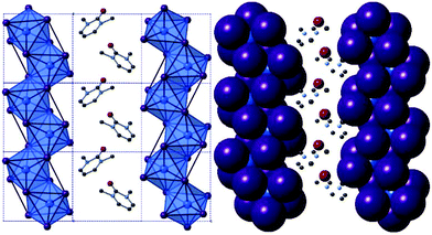
Compounds I and II, [C6H9N2O][MI4], M = Sb, Bi. The isostructural 1,3-dimethyl-2-oxo-2,3-dihydropyrimidinium templated structures I and II, were solved from single crystal X-ray diffraction data; see Table 1 for crystallographic data comparison. In each synthetic procedure the simpler organic amine 2-aminopyrimidine was used as a precursor reagent; however under the high temperature and pressure conditions of the solvothermal reaction, and in the presence of strong acid HI, methyl iodide forms as a transient species before undergoing alkylation of the two pyrimidine ring nitrogen positions in turn and deprotonation of the amine to form the mono-cationic organic ion 2-imino-1,3-dimethyl-2,3-dihydropyrimidium. Under the acidic aqueous conditions a further reaction occurs in situ in which the imine is hydrolysed to a ketone functionality resulting in the templating cationic 1,3-dimethyl-2-oxo-2,3-dihydropyrimidinium species. The structures of both compounds I and II exhibit an anionic network of one-dimensional metal halide chains [MX4]n− interacting via weak halide–halide connections.25,32,46 In the channels between the anionic network, the organic cations (counter-balancing the charge of the anionic chains) are positioned to fill the grooves of the chain structure along the a/c plane axis (see Fig. 1); alternating with perpendicular orientation along the b-axis indicative of a herring-bone structural motif (see Fig. 2c-axis view).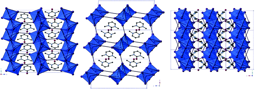 | ||
| Fig. 2 Visualisation of structure II (iso-structural with structure I) along a-axis (left), b-axis (centre) and c-axis (right); key as in Fig. 1. | ||
| Compound I (Sb) | Compound II (Bi) | |
|---|---|---|
| Space group | Monoclinic P21/c | Monoclinic P21/c |
| a (Å) | 10.5506(4) | 10.6424(3) |
| b (Å) | 7.6199(3) | 7.6380(2) |
| c (Å) | 19.9962(7) | 20.0271(5) |
| β (°) | 95.336(3) | 94.986(2) |
| V (Å3) | 1600.63(10) | 1621.78(7) |
Weak inter-chain I⋯I interactions extend the anionic network asymmetrically along the a- and c-axes of both structures. A terminal-terminal I⋯I pathway bridges the anionic chains in, approximately, the a-axis direction. For structures I and II, respectively, these separations are 3.85 Å and 3.79 Å, repeating every 7.62 Å and 7.64 Å along the b-axis. Similarly, (for structures I and II respectively) a longer edge-terminal I⋯I interaction of 4.42 Å and 4.32 Å, repeating more regularly every 4.03 Å and 4.12 Å, approximately along the c-axis direction can be observed. The average I⋯I interaction distance for the iodobismuthate compound is shorter at 4.06 Å, in comparison to 4.14 Å for the iodoantimonate.
The chain structure is formed by edge-sharing of metal iodide octahedral units along two of twelve vertices. The octahedra appear to distort away from ‘perfect’ regular octahedra in accordance with the known trans effect in halometallate structures wherein the M–X bonds across from bridging bonds are shorter (and also exhibit a higher vibrational frequency).47,48 However, an additional degree of distortion may be attributed to the way in which the cations are interleaved within the grooves of the chain structure (highlighted in Fig. 1). Deviation of the I–M–I bond angle away from an ideal 180 degrees within the octahedra ranges from 4.9–10.9° in structure I to 5.9–11.6° in structure II. Average bond angle deviations show distortions of 7.3° and 7.8°, respectively, away from a regular octahedron in each of the structures.
In addition to this, considering the M–I–M bond angles within the chain structures shows an average bond angle deviation from 90° of 3.9° for the [SbI4]n− chains in compound I compared to 3.5° for the [BiI4]n− chains in compound II. M–I bond distances vary by 2.83–3.27 Å (Δ = 0.44 Å) 2.92–3.29 Å (Δ = 0.37 Å) for structures I and II respectively.
Compounds III and IV
From single crystal X-ray diffraction data, the structures of two 4-methylmorpholinium templated hybrid structures have been derived. Compound III, [C5H12NO]4[Sb6I22], contains clusters of four monovalent charged 4-methylmorpholinium cations charge counter-balancing discrete [Sb6I22]4− anions.3 Each cation is orientated with the ring-based oxygen atom directed towards the core of the cation cluster and, thus, the positively charged protonated nitrogen atom (and attached methyl group) directed outwards from the cluster and in closer proximity to the anionic units. Each group of four cations is “encased” within an anionic sublattice formed by six [Sb6I22]4− units linked through weak I⋯I interactions. Consideration of the orientations of the four 4-methylmorpholinium cations within each cluster indicates that there are no, or extremely weak, hydrogen bonding interactions between protonated amine template cation and [Sb6I22]4− anions (Fig. 3).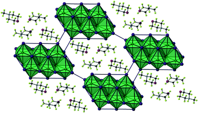 | ||
| Fig. 3 A single layer component of structure III viewed on the ab plane. Key as in Fig. 1 aside from [SbI6] octahedra shaded teal; Sb atoms (teal), H atoms (pale green). | ||
Further analysis of this structure shows that viewed down the c-axis the discrete iodoantimonate units are interconnected by weak I⋯I interactions of 4.64 Å between the outer Sb(1) octahedra and two I⋯I interactions of 4.21 Å per Sb(3) octahedra. Further weak I⋯I interactions interconnect each [Sb6I22]4− unit with a total of 38 interactions (12 repeating unique I⋯I distances) per unit to 12 distinct zero-dimensional [Sb6I22]4− units to build the anionic “network”. Overall these inter-unit interactions range from 3.80–4.73 Å; with an average I⋯I interaction distance of 4.14 Å.
The outermost octahedra in each [Sb6I22]4− unit, centred by position Sb(1) with just two from twelve possible edge connections, is the most perceptibly distorted and this can be shown by considering the average deviations from 180° for the I–Sb–I angles in each [SbI6] octahedra. For the Sb(1) centred octahedra the angle was found to distort by 10.3° from 180° on average. For the Sb(3) centred octahedra, with 3/12 edge connections along its vertices, the average angle deviation from 180° for I–Sb–I is reduced to 6.7°. Lastly, with 4/12 edge connections to adjacent octahedra, the Sb(2) centred octahedra making up the core of the [Sb6I22]4− unit exhibits least distortion from a regular octahedron with an average deviation away from 180° of just 2.9°. Bonded Sb–I distances within each octahedra vary by 2.76–3.47 Å (Δ = 0.71 Å), 2.79–3.36 Å (Δ = 0.57 Å) and 2.79–3.35 Å (Δ = 0.56 Å) for Sb(1)–(3) respectively (Fig. 4).
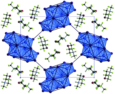 | ||
| Fig. 4 A cross-section of the bc plane of structure IV viewed down the a-axis; colour key as in Fig. 1 with addition of O atoms (red) and H atoms (pale green). | ||
Iodobismuthate hybrid material (structure IV) [C5H12NO]4[Bi4I16], again templated by 4-methylmorpholinium cations, was modelled from the single crystal X-ray diffraction data. In a similar way to its iodoantimonate counterpart, discussed previously, groups of four monovalent 4-methylmorpholinium cations are found to cluster together; again encapsulated by the anionic sublattice structure. However, here the counter-balancing tetravalent discrete anionic units take the form of [Bi4I16]4−.7 A total of 28 (7 repeating unique I⋯I distances) inter-unit I⋯I interactions connect each discrete bismuth iodide unit to twelve different [Bi4I16]4− units. Inter-unit I⋯I interaction distances range from 3.97–4.56 Å; with an average distance of 4.27 Å. Orientation of the 4-methylmorpholinium suggests weak hydrogen bonding interaction between cations (N+–H⋯O) may be present within the structure D–H⋯O (hydrogen bond distance 1.95 Å with a ∠D–H⋯A angle of 157.6° (22.4° deviation from direct interaction)) from position N(2)–H to O(1). The N(1)–H and O(2) positions are not involved in hydrogen bonding (Table 2).
| Compound III (Sb) | Compound IV (Bi) | |
|---|---|---|
| Space group | Triclinic P-1 | Orthorhombic Pbca |
| a (Å) | 11.3253(7) | 12.7627(3) |
| b (Å) | 13.0042(7) | 20.7207(6) |
| c (Å) | 15.2847(7) | 22.7427(6) |
| α (°) | 69.645(4) | 90.000 |
| β (°) | 69.877(5) | 90.000 |
| γ (°) | 64.496(6) | 90.000 |
| V (Å3) | 1853.97(17) | 6014.35(3) |
The outer Bi(1) centred octahedra are visibly more distorted than the central Bi(2) octahedra within each [Bi4I16]4− unit. Averaging the angular deviation away from 180° across all trans I–Bi–I motifs in the octahedra reveals a distortion of 9.8° for the Bi(1) centred outer octahedra compared to 5.4° for the core Bi(2) centred octahedra. However, the influence of the trans effect, wherein the M–X bonds across from bridging bonds are shorter, is similar in each octahedra with Bi–I distances varying by 2.89–3.42 Å (Δ = 0.53 Å) and 2.88–3.40 Å (Δ = 0.52 Å) for Bi(1) and Bi(2) respectively.
Compounds V–IX
The structures of Compounds V–IX were solved from single crystal X-ray diffraction. Structures V, VI, VII and VIII [NH2(CH2)4NH2][SbI4]2·4H2O, [CH3NH(CH2)4NH2][SbI4]2·3H2O, and [CH3NH(CH2)4NHCH3][SbI4]2·2H2O (two polymorphs) were templated by 1,4-dipiperazinium, 1-methyl-1,4-dipiperazinium and 1,4-dimethyl-1,4-dipiperazinium cations respectively. The materials are iso-structural and consist of infinite one-dimensional antimony iodide [SbI4]n− chains with fairly short inter-chain I⋯I contacts.32 Divalent charge-balancing cations are located within channels extending along the a-axis direction parallel with the sub-lattice of 1D [SbI4]n− chains. Associated with the changes in the degree of methylation of the nitrogen positions on the piperazine ring system is a variation in the level of water incorporated into the material – which reduces as the methyl groups protrude into the space occupied by the water molecules. There is a related subtle alteration to the [SbI4]n− chain positions relative to each other and thus their degree of interaction via interlinking I⋯I connections (Table 3).| Compound V | Compound VI | Compound VII | Compound VIII | Compound IX | |
|---|---|---|---|---|---|
| Space group | Monoclinic P21/c | Monoclinic P21/c | Monoclinic P21/c | Monoclinic P21/c | Monoclinic P21/n |
| a (Å) | 7.3391(2) | 7.5306(2) | 7.7213(2) | 7.5751(2) | 11.5391(3) |
| b (Å) | 13.0022(5) | 12.9539(4) | 12.8027(3) | 12.1020(3) | 11.8717(4) |
| c (Å) | 13.8121(4) | 13.6147(4) | 13.4527(3) | 14.5071(4) | 19.1648(5) |
| β (°) | 94.550(3) | 96.086(3) | 97.377(2) | 92.630(3) | 93.705(3) |
| V (Å3) | 1313.86(7) | 1320.64(7) | 1318.84(5) | 1328.52(6) | 2619.87(13) |
Similar to the equivalent iodobismuthate material described in a previous publication,49 structure VI has the 1-methyl-1,4-dipiperazinium cation disordered between two orientations within the channel. An effect of this is that two of the water molecule positions within the structure become partially occupied depending on the orientation of the cation and thus the directionality and steric hindrance by the methyl (CH3) group on these hydrated sites. Consequently, two previously fully occupied water molecule positions in structure V become half-filled, reducing the overall degree of hydration from a tetrahydrate (in the composition of structure V) to an averaged trihydrate (in the composition of structure VI). Continuing the trend, in the isomeric structures VII and VIII, 1,4-dimethyl-1,4-dipiperazinium ions within the channel impede occupancy of two of the would-be hydrated sites within the structure; having the effect of reducing the overall level of hydration within the material to a dihydrate composition; [CH3NH(CH2)4NHCH3][SbI4]·2H2O.
The iodometallate [MI4]n− chains in structures V, VI, VII and VIII consist of edge sharing [MX6] octahedra; with four bridging iodine atoms along two vertices and two cis-related terminal iodine positions. The antimony atom position is offset from a central position within the octahedra with the shortest two Sb–I distances observed for the two cis terminal iodine sites. These observations are in agreement with those made for previously studied materials possessing a similar [MX4]n− structural motif for haloantimonates and halobismuthates exhibiting the trans effect; vide supra. Similarly, the spread of Sb–I bond lengths within the octahedra, that interlink to form the chains, decreases from compound V to compound VII suggesting an increased overall regularity of the octahedra.
Much like their counterpart iodobismuthate hybrid structures, inter-chain I⋯I interactions in Compounds V–VIII extend the anionic network along b- and c-axes of each material. It can be considered that the pathways across this interface produces a level of pseudo-dimensionality within the anionic sublattice framework of the materials; introducing the potential electronic pathways across [SbI4−]n chains in addition to movement along the chain. Two edge-terminal I⋯I and a terminal-terminal I⋯I interaction repeat regularly (7.34 Å, 7.53 Å and 7.72 Å respectively) along the chain a-axis; with all iodide positions within the network in close enough proximity to engaged in at least one inter-chain interaction. Lengths of these interactions range from 3.80–4.46 Å in the structures and the average distance of the inter-chain interactions decreases 4.19 Å → 4.13 Å → 4.01 Å through compounds V–VII respectively. However, the shortest I⋯I interaction is shown to undergo negligible change through the structures; 3.80 Å → 3.81 Å → 3.80 Å. In response inter-chain Sb–Sb distances are observed to increase marginally by 0.05 Å and 0.08 Å in the structural pairs V → VI and VI → VII respectively. Variation in the Sb–I–Sb bond angles within the chains also sees an increase away from regular octahedral angle to 90.7° → 92.1° → 93.6° for structures V–VII respectively.
In summary as the piperazinium ring of the organic cation becomes increasingly methylated there are observable changes the anionic sub-lattice of each structure. The regular distance between repeat interactions along the chain structure in the a-axis direction increases (i.e. an increasingly less compressed framework along the a-axis) the average I⋯I inter-chain interaction distance decreases (4.19 Å → 4.13 Å → 4.01 Å) and the overall regularity of the octahedra, defined by decreasing Sb–I bond length variation, increases (0.49 Å → 0.45 Å → 0.40 Å). Overall, structures V–VII follow similar structural trends to their iodobismuthate equivalent materials previously reported.49
In addition to these findings on antimony iodide 1,4-dipiperazinium complexes a new polymorph of compound VII crystallised in the same reaction mixture, together with a third phase, vide infra. This first minor phase of elongated dark orange needles, identified as compound VIII, occurred together with the major phase of blocky, dark orange crystals of structure VII. The structure of compound VIII consists of an identical motif of interconnected [SbI4]n− chains as seen in structure VII, however, the interrelationship between the chains for VIII shows an offset of approximately 19° in comparison with respect to adjacent units in the sublattice network. As a result, as seen in the a-axis view of structure VIII (see Fig. 5), the chains become aligned in parallel. Furthermore, comparing structures VII and VIII it can be seen that the three repeating interchain I⋯I interactions along the chain axis are retained, however, although the regularity of recurrence of these interactions along the a-axis is decreased (7.72 Å → 7.58 Å) the average interaction distance sees a slight increase (4.01 Å → 4.07 Å). In addition to this, the regularity of the octahedra decreases (Δ 0.40 Å → Δ 0.48 Å) and the Sb–I–Sb angle within the chain decreases by 1.1° (93.6° → 92.5°). Furthermore, it can be observed that, in structure VIII, the di-cation positioning within the a-axis channel shows increased tilt with the methyl groups pointed along the propagating a-axis more than in the polymorph (VII); in which the directionality of the methyl groups is focussed more towards the interstitial interchain space.
 | ||
| Fig. 5 Left to right: Structures V–VIII viewed along the a-axis and the asymmetric unit cell of structure IX; colour key as in Fig. 1 aside from Sb atoms (teal) and O atoms (red). | ||
Finally, a third 1,4-dimethyl-1,4-dipiperazinium cation templated structure [CH3NH(CH2)4NHCH3][Sb4I16]0.5·H2O (compound IX), determined from single crystal X-ray diffraction data, was found to crystallise in the form of yellow-orange block-shaped crystals. Comparatively to the counterpart structures (VII and VIII) it crystallised alongside, the material contains a lower dimensional Sb–I anionic sub-structure of [Sb4I16]4− units.50 In each unit cell, two divalent 1,4-dimethyl-1,4-dipiperazinium cations counterbalance the anionic network of zero-dimensional [Sb4I16]4− units. Each anionic unit interacts with a total of 14 different adjacent units to build the substructure via 36 (10 repeating unique I⋯I distances) inter-linking weak I⋯I interactions. Distances range from 4.09–4.64 Å; with an average distance of 4.25 Å. The level of solvation within the structure is reduced with respect to structures VII and VIII from a dihydrate (1![[thin space (1/6-em)]](https://www.rsc.org/images/entities/char_2009.gif) :
:![[thin space (1/6-em)]](https://www.rsc.org/images/entities/char_2009.gif) 2 dication to water molecule ratio) to a monohydrate hybrid material (1
2 dication to water molecule ratio) to a monohydrate hybrid material (1![[thin space (1/6-em)]](https://www.rsc.org/images/entities/char_2009.gif) :
:![[thin space (1/6-em)]](https://www.rsc.org/images/entities/char_2009.gif) 1 ratio).
1 ratio).
The outer Sb(2) centred octahedra of the [Sb4I16]4− cluster show distortion from regularity with an average angle deviation (away from 180° across I–Sb–I) in octahedra of 10.5°; compared to 4.4° for the central Sb(1) centred positions in the cluster. In accord with this observation is a larger variation in the Sb–I bonding distances within the outer octahedra compared to the inner; showing a variation covering the distance range 2.82–3.27 Å (Δ = 0.45 Å) for the Sb(1)-centred octahedron and 2.78–3.47 Å (Δ = 0.69 Å) for Sb(2) (Fig. 6).
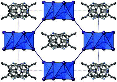 | ||
| Fig. 6 Structure XI [C10H13N2][BiI4] viewed down the c-axis (hydrogen atoms are not shown); colour key as in Fig. 1. | ||
Compounds X and XI
Structures X, [C10H13N2][SbI4], and XI, [C10H13N2][BiI4], were solved from single crystal X-ray diffraction data. The hybrid materials are isostructural and consist of inter-linked (through weak I⋯I interactions) metal iodide one-dimensional chains forming irregular sided octagonal channels in which the charge balancing organic cations are positioned. The templating cation for both isomorphs is the monovalent cation 1-ethyl-2-methylbenzimidazolium; formed in situ by twofold alkylation of the precursor reagent 1,2-benzenediamine via a ring-closing mechanism by reaction with ethyl iodide (formed in the reaction mixture from the solvent ethanol and HI). The materials both adopt a monoclinic crystal system, however, they crystallise in different space groups; see Table 4. This difference is related positional changes and disorder of the organic benzimidazolium cation within the channel. Propagating along the a-axis, for structure X, and c-axis, for structure XI, the cations stack with alternating orientations (180° rotation) with a separation of approximately 3.7 Å and an offset from the associated perpendicular structural axis of 17° and a shift of 1.6 Å. It should be noted that in the structure solution of compound X the organic component was modelled with PARTS instruction in order to split the ion into 55/45 occupancy over two related positions; the direction of the benzimidazolium ion alternates between these two positions, with the relationship between the two positions determined as an approximate 25° rotation in-plane of the ring system followed by a 180° 2-fold rotation through the central in-plane axis of the ion. Compound XI, however, was modelled in the higher symmetry monoclinic space group C2/c. Here, the 1-ethyl-2-methylbenzimidazolium cation lies on a glide plane running along the channel length.| Compound X (Sb) | Compound XI (Bi) | |
|---|---|---|
| Space group | Monoclinic P21/n | Monoclinic C2/c |
| a (Å) | 7.5877(3) | 13.3133(4) |
| b (Å) | 17.7055(8) | 17.7312(4) |
| c (Å) | 13.2578(6) | 7.6344(2) |
| β (°) | 94.309(4) | 93.450(2) |
| V (Å3) | 1776.07(13) | 1798.92(8) |
As previously mentioned, in both structures X and XI the anionic framework is made up of one-dimensional anionic chains with the compositions [SbI4]n− and [BiI4]n− respectively.25 In each structure the chains are aligned in parallel and consist of linked [MI6] octahedra; each octahedron has two cis-related terminal iodine positions with the other four iodine positions along shared edges of the octahedron. Within each octahedron the metal atom position is displaced from a central ‘regular’ octahedra position in the direction of the two terminal iodine positions with the two M–I(terminal) bond lengths approximately 0.5 Å shorter than to the other iodine positions. This is structural feature common to many iodobismuthate and iodoantimonate one-dimensional chain [MI4]n− hybrid structures. Comparing the antimonate (X) to the bismuthate (XI) structure it can be seen that the overall metal–iodide bond length range is slightly reduced (by 0.05 Å), producing more regular octahedra, and there is the expected shift to a higher average bond length (+0.05 Å) with the larger Bi. Similarly from X(Sb) to XI(Bi), the M–I–M bond angle average within the chain unit decreases from 93.5° to 93.0°. In both structures a single weak inter-chain I⋯I interaction is seen to repeat along the chain axis direction; with a distance of 4.06 Å (Sb) and 3.94 Å (Bi) with a repeat distance of 7.59 Å(Sb) and 7.63 Å(Bi).
Also of note, is that the one-dimensional [MX4]n− chain structural motif observed in these materials is reminiscent of structure VIII. However, due to the increased size and reduced charge density of the monovalent 1-ethyl-2-methylbenzimidazolium cations compared to the 1,4-dimethyl-1,4-dipiperazinium divalent cations the void size accommodating the organic cations is larger; approximately 11.2 × 9.8 Å for X and XIversus 7.9 × 8.2 Å for structure VIII (Fig. 7).
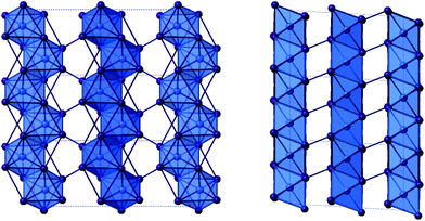 | ||
| Fig. 7 The [BiI4]n− chain units of structure XI viewed down the a-axis (left) and b-axis (right). Colour key as in Fig. 1. | ||
Compounds XII, XIII and XIV
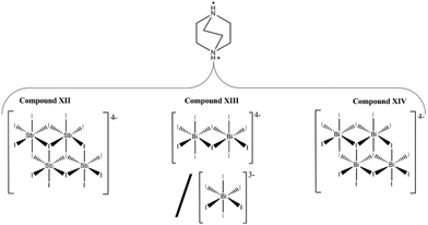
The iodoantimonate hybrid structure [C6H14N2]2[Sb4I16]·2H2O (compound XII) was determined from single-crystal X-ray diffraction analysis. The material contains zero-dimensional tetra-octahedral [Sb4I16]4− anionic units which are counter-balanced by two di-protonated 1,4-diazabicyclo[2.2.2]octan-diium (DABCOH2) cations (see Fig. 8) alongside two sites occupied by water molecules. Within the structure each anionic [Sb4I16]4− structural unit interacts through weak I⋯I interactions, 38 (11 unique I⋯I bonding modes) interlinking pathways exist to a total of 12 nearby equivalent units to build the anionic “sub-lattice”. I⋯I interaction distances range from 4.01–4.59 Å; with an average distance of 4.34 Å.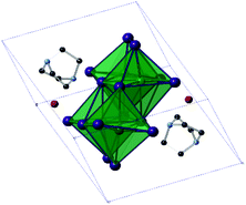 | ||
| Fig. 8 Symmetric unit cell of structure XII (hydrogen atoms excluded); colour key as in Fig. 5. | ||
The structure is reminiscent of structures IV and IX, each containing the 0D [M4I16]4− structural motif, each tetra-octahedral unit contains two equivalent central octahedra (with three shared edges) and antimony–iodide bond lengths ranging from 2.85–3.24 Å (Δ = 0.39 Å). The more distorted outer octahedra (which have two edges shared with other octahedra) show an increased metal–iodide bond length range of 2.79–3.39 Å (Δ = 0.60 Å). This variation in octahedron irregularity is also reflected in the average angle deviation from 180° of the trans I–Sb–I angles within the MX6 octahedra. I–Sb–I angles have an average deviation of 5.8° from 180° for the inner octahedron centred on Sb(1), whereas the outer octahedron, centred on Sb(2), exhibits a much greater deviation of 12.3°.
In further reactions, using 1,4-diazabicyclo[2.2.2]octan-diium (DABCOH2) di-cations as templating agents, a mixed phase of two new iodobismuthate hybrid material structures were obtained. Compound XIII, formulated as [C6H14N2]10[Bi2I10]2[BiI6]4·(H2O)8 contains a unique and previously unreported combination of structural motifs, with both [Bi2I10]4− and [BiI6]3− anionic components.10,51
In each unit cell there are two di-octahedral [Bi2I10]4− units and four discrete [BiI6]3− units generating a total anionic composition of [Bi8I44]20−. Eight di-protonated (DABCOH2)2+ form the main charge-balancing organic component of the structure with positions identified within the structural model. This balancing leads to a charge deficit of 4+ per asymmetric unit cell and so to achieve an overall compositional charge neutrality to the material it is proposed that two unrefined (DABCOH2)2+ dications reside within structural pores; as seen in Fig. 10. This is in agreement with the results of the solvent masking algorithm utilised, detailed within the crystallographic data, suggesting that electron density within the structural pores is consistent with the presence of two additional disordered dications (Fig. 9).
 | ||
| Fig. 9 Thermal ellipsoid plots (probability set at 50%) for structure XII (below), structure XIII (centre) and structure XIV (right). | ||
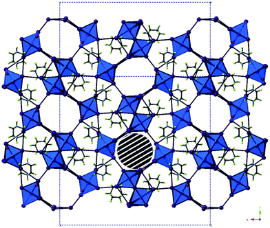 | ||
| Fig. 10 The structure of compound XIII viewed down the a-axis. The striped area marks one pore containing disordered DABCO di-cations; colour key as in Fig. 1 with O atom sites (red) and H atoms (green). | ||
To elaborate, along the a-axis of compound XIII (see Fig. 10) a large slightly irregular octahedral channel, approximately 9.0 × 8.5 Å in dimensions, propagates through the structure. In conjunction, a minor channel, approximately 4.7 × 4.2 Å in size, extends along the c-axis and intercepts the major channel running along a. Provided the weak I⋯I interactions are sufficiently robust this hybrid structure may have the potential for ion exchange and porosity. In addition to this eight water molecule positions have been identified within the structural model. Due to the heavy atom sites present accurately determining the orientation of bonded hydrogen atoms at each solvated sites using X-ray diffraction data is problematic (Table 5).
| Compound XII (Sb) | Compound XIII (Bi) | Compound XIV (Bi) | |
|---|---|---|---|
| Space group | Triclinic P![[1 with combining macron]](https://www.rsc.org/images/entities/char_0031_0304.gif) |
Orthorhombic Pbam | Monoclinic P21/c |
| a (Å) | 10.8634(3) | 31.9562(6) | 11.0086(3) |
| b (Å) | 10.8965(3) | 15.8622(4) | 15.4751(3) |
| c (Å) | 11.2911(3) | 8.6164(2) | 15.3455(4) |
| α (°) | 91.999(2) | 90.000 | 90.000 |
| β (°) | 109.691(2) | 90.000 | 103.001(2) |
| γ (°) | 95.086(2) | 90.000 | 90.000 |
| V (Å3) | 1250.46(6) | 4367.62(17) | 2547.23(11) |
Bi–I bond lengths within the [BiI6] units ranges from 3.00–3.18 Å (Δ = 0.18 Å) and demonstrate only a minor deviation, of 3.1°, (trans I–Bi–I angles) from 180°. In comparison, within each [Bi2I10]4− unit the metal–iodide bond lengths ranges from 2.96–3.24 Å (Δ = 0.28 Å); the longest M–I bonds are to the edge-shared iodide positions linking the octahedra. The position of the central bismuth ion within the individual octahedra of the [Bi2I10]4− unit is shifted slightly towards the terminal iodide positions. Regularity of the octahedra within the di-octahedral unit is still high; with only a minor average deviation (from trans angles of 180°) of 4.3° observed.
As previously mentioned, a secondary phase was found to have crystallised in association with compound XIII. The structural analysis of this phase (compound XIV) showed that it was also a di-protonated DABCO templated hybrid iodobismuthate but with a differing structural composition; determined as [C6H14N2]2[Bi4I16]·2H2O (Fig. 11).
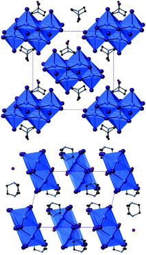 | ||
| Fig. 11 Structure XIV viewed down the a-axis (top) and down the b-axis (bottom); colour key as in Fig. 10. | ||
The structure of XIV contains discrete tetra-octahedral [Bi4I16]4− unit which interact along weak I⋯I connections to ten adjacent [Bi4I16]4− units; there are a total of 34 such interactions (9 unique bonding modes). Interaction lengths range from 4.06–4.52 Å (Δ = 0.46 Å) with an average distance of 4.31 Å. As seen in compounds (IV, IX, XII) the tetra-octahedral units contain two distinct Bi sites. In compound XIV the Bi(1) outer octahedral positions, bound to adjacent octahedra by 2 from 12 possible edge connection sites, exhibit M–I bond lengths in the range of 2.91–3.34 Å (Δ = 0.43 Å); very similar distances are seen for the Bi(2) inner octahedral positions (3/12 edge connections) with a range of 2.90–3.29 Å (Δ = 0.39 Å).
Deviation of the trans I–M–I angles within the octahedra from 180° shows an average of 9.5° for the outer Bi(1) site and 9.1° for Bi(2) inner site. The relatively small distortion of the outermost two octahedra within the tetra-octahedral unit may be compared to that seen previously in materials with the same anionic motif. The increased regularity found in compound XIV may be due to the lessened strain from reduced number of interunit I⋯I interactions to just ten nearby equivalent units. This compares to twelve such links seen for structures IV and XII and fourteen for structure IX, which saw the greatest M–I bond length range with Δ = 0.69 Å (Table 6).
| Compound | Structural formula |
|---|---|
| I | [C6H9N2O][SbI4] |
| II | [C6H9N2O][BiI4] |
| III | [C5H12NO]4[Sb6I22] |
| IV | [C5H12NO]4[Bi4I16] |
| V | [C4H12N2][SbI4]2·4H2O |
| VI | [C5H14N2][SbI4]2·3H2O |
| VII | [C6H16N2][SbI4]2·2H2O |
| VIII | [C6H16N2][SbI4]2·2H2O |
| IX | [C6H16N2][Sb4I16]0.5·H2O |
| X | [C10H13N2][SbI4] |
| XI | [C10H13N2][BiI4] |
| XII | [C6H14N2]2[Sb4I16]·2H2O |
| XIII | [C6H14N2]10[Bi2I10]2[BiI6]4·(H2O)8 |
| XIV | [C6H14N2]2[Bi4I16]·2H2O |
Structure stability and dehydration
From thermogravimetric analysis studies (ESI – Fig. S1†) compound I, [C6H9N2O][SbI4], shows a stable mass with negligible change on heating to approximately 210 °C, followed by a major degradation step (Δm% = −86%) between 210 and 320 °C. This is likely to be associated with complete decomposition of the amine and loss of iodine from the material; the fastest mass loss occurs from 280–300 °C. A further steady low rate of mass loss occurred on heating to the maximum furnace temperature of 400 °C; leaving residual mass (∼1.2 mg) of antimony metal.For compound II, [C6H9N2O][BiI4], a stable thermal profile is observed up to 150 °C before a series of sharp, small, weight losses, equating to total loss (Δm%) of 10%, occurs between 150 and 210 °C. These weight losses can be attributed rapid, possibly locally explosive decomposition of the amine. The remaining bulk mass is stable to 250 °C before undergoing a continuous large mass loss step (Δm% = 70%) on heating to 400 °C, with the fastest mass loss occurring between 330 and 355 °C. A still reducing mass of ∼2.5 mg of bismuth is present at Tmax. This weight loss corresponds to further degradation of any residual amine and its decomposition products and the loss of HI/I2 leaving the residue of bismuth metal.
TGA studies on 4-methylmorpholium templated compounds III and IV (ESI – Fig. S2†) showed that each exhibits a one-step thermal degradation process. For structure III, a stable plateau is observed in the thermal profile up to 180 °C, from which point, in the temperature range of 180–320 °C, major degradation of the compound occurs with a total mass loss Δm% = 92%. The fastest rate of mass loss occurred from 260–300 °C, with decomposition of the amine and loss of HI/I2, and a stable residual (∼1 mg) mass of antimony metal is retained up to the highest temperature reached of 400 °C. In comparison, the bismuth-containing structure (IV), with a different anionic sublattice, showed an increased stability of +60 °C over its counterpart, with a prolonged degradation of the hybrid material occurring only from 240–400 °C (Δm% = 90%); the residual mass, of approximately 2 mg, was bismuth metal.
Thermal analysis the piperazinium-based hybrid materials was carried out and the resultant traces are shown in ESI – Fig. S3.† Data for tetrahydrate compound V showed an initial expected dehydration step between 80 and 110 °C (Δm% = 5%) before a stable mass is retained up to 180 °C. From 180–260 °C (Δm% = 36%) is the first of two major degradation steps of the remaining hybrid material; followed immediately by the second step in the temperature range of 260–340 °C (Δm% = 54%). Similarly, for isolated crystals of trihydrate compound VI, a dehydration step 95–125 °C with a proportionately lower relative mass loss (Δm% = 3.4%) was observed. After a stable plateau, until 175 °C, further degradation between 175 and 305 °C was observed; with temperature range 290–305 °C showing the highest rate of degradation. A further slow loss of weight, likely to be due to evolution of iodine, occurred between 305 and 345 °C, at which temperature a stable residue was formed. Lastly, a mixed phase sample of structures VII–IX was analysed thermogravimetrically. A minor weight loss associated with dehydration of all three phases was observed in the temperature range 90–120 °C; (structures VII and VIII were determined to be dihydrates and structure IX a monohydrate). Following this the compounds remained stable to 175 °C until major degradation from 175–355 °C (Δm% = 96%). All three piperazinium-based templated materials were determined to remain stable to approximately the same temperature; around 175–180 °C, before major degradation. Following this simultaneous decomposition of all three phases a residue of antimony metal (∼0.7 mg) was obtained with no notable mass change between 350 and 400 °C.
The nature of main degradation process of all the compounds (following loss of any water from the structure) is decomposition of the amine, and this may be associated with simultaneous loss of HI/I2. The decomposition transitions from a clear two-step process for compound V to a continuous one-step process for structures VII–IX, presumably due to the differing stabilities of the templating cations. As the piperazinium-ring based di-cation in each structure becomes increasing methylated its effect on slowing the degradation process becomes reduced; as observed in the shift in remaining mass of each compound in temperature range 290–320 °C. This is reflected in the temperature at which maximum mass change occurs in each profile; with structure V indicating a maximum mass loss rate of −1.90 mg min−1 at 325 °C, −2.0 mg min−1 at 310 °C for structure VI and −1.65 mg min−1 at 285 °C for structures VII/VIII/IX.
Analysis of isostructural compounds X and XI shows a distinct effect of changing of metal within the hybrid material composition (ESI – Fig. S4†). For structure X, other than a minor mass loss at 185 °C, likely to derive from the 10% impurity phase of organic iodide, the thermal profile shows a stable mass to approximately 225 °C. In comparison, the equivalent bismuth compound, XI, demonstrates a much increased thermal stability over its counterpart, to around 280 °C. Each structure undergoes a continuous one-step degradation process, however, antimony-based structure X showed an increased rate of degradation with a max rate of change of mass of −2.30 mg min−1 occurring at 340 °C, compared to −1.65 mg min−1 at 385 °C for structure XI. As a result, a residue metal mass was left for structure X from temperature range 350–400 °C whereas, for structure XI a residue mass remained at 400 °C with a much slowed rate of mass change still occurring, as the full decomposition pathway was incomplete at this temperature.
Finally, thermogravimetric analysis was carried out on DABCOH2 di-cation templated materials compound XII and a mixed phase of iodobismuthate compounds XIII/XIV (ESI – Fig. S5†). Iodoantimonate structure XII undergoes a distinct 3-step degradation process. The first and shortest step occurs at temperature range 205–230 °C; with a max dTG of −1.25 mg min−1 at 215 °C. The second at temperature range 230–280 °C; with a max dTG of −1.25 mg min−1 at 265 °C. The third and longest step occurs at temperature range 280–350 °C; with the highest dTG in the thermal profile of −2.15 mg min−1 peaking at 315 °C. A low temperature dehydration step is not observed for the material which may be attributed to the fact that the water sites are encapsulated within a zero-dimensional anionic sublattice with no open channels for rapid dehydration to occur. From 350 °C to Tmax an expected ∼1 mg metal residue mass remains. The TGA trace of the mixed phase of iodobismuthate hybrid structures XIII and XIV shows a stable thermal profile up to approximately 260 °C. From 260–400 °C degradation of the materials occurs, initially at a slow rate followed by a rapid increase to a max dTG of −2.15 mg min−1 peaking at 315 °C. Degradation of the materials then slows but continues up to Tmax at which a still slowly degrading residual bismuth metal mass remains.
Optical absorption measurements
Optical absorption spectra (250–800 nm) were collected for Compounds I–XIV (ESI Fig. S6–S10†). Analysis of isostructural compounds I and II (ESI – Fig. S6†) shows absorbance in the ultraviolet and visible region with increasing intensity up to the absorption edge onsets at 485 nm and 540 nm respectively. An additional absorption peak feature is observed within the ultraviolet region at 320 nm for structure I. Assuming a direct band gap for these materials gives Eg values of 2.13 eV and 2.05 eV; a change of −0.08 eV as a result of changing antimony to bismuth.Similarly, analysis of 4-methylmorpholium containing compounds III and IV (ESI – Fig. S7†) shows strong absorbance across the ultraviolet and visible regions up to the absorption edge onsets at 460 nm and 515 nm in turn. Changing the metal from antimony to bismuth and metal iodide anionic moiety from [M6I22] to [M4I16] results in a reduction in the estimated Eg values (assuming a direct band gap) by 0.22 eV from 2.28 eV to 2.06 eV.
The piperazinium-based structures V–IX (ESI – Fig. S8†) shows strong absorbance across the ultraviolet and visible regions up to absorption onsets at 480 nm, for both compounds V and VI, and at 500 nm for the mixed phase sample of structures VII–IX. As for the equivalent iodobismuthate materials studied previously, additional absorption peak features can be observed in the spectra for structure V (at 285 nm and 355 nm) and structure VI (at 290 nm and 360 nm). Features akin to this can also be observed at similar wavelengths in the spectrum obtained from the mixed phase sample (containing compounds VII–IX), although the strength of absorption is suppressed and seen as broad peaks. The estimated band gap energy reduces by 0.05 eV for the series of compounds V → VI → VII/VIII/IX from 2.22 eV → 2.17 eV → 2.12 eV respectively. As the templating piperazinium-ring dication becomes increasingly methylated there is an increase in the connectivity of the anionic sublattice, through weak I⋯I interactions, as the average [SbI4]n−–[SbI4]n− interchain distances reduce. This is likely to be the origin of the slightly reduced band gap across this series.
Isostructural compounds X and XI show absorption in the ultraviolet and visible regions with increasing absorption strength towards their respective absorption edge onsets at 470 nm and 525 nm. Both structures exhibit an identical dual pointed absorption feature (at 270 nm and 275 nm) in the ultraviolet region. An additional absorption peak can be seen at 675 nm in both spectra beyond after the main absorption edge. The commonality of this feature to both compounds X and XI suggests it can be attributed to an electronic transition occurring locally on the conjugated 2-methylbenzimidazolium cation, a component present in both the isostructural compounds. Band gap estimates from the Tauc plot show a large shift of 0.3 eV between the two 2-methylbenzimidazolium templated structures; with respective Eg values of 2.33 eV for antimony based structure X and 2.03 eV for bismuth based structure XI.
UV-vis spectra were also collected for the DABCOH2 di-cation templated hybrid materials. The iodoantimonate compound XII shows an absorption edge onset at 515 nm; compared to an approximate absorption edge of 520 nm for mixed phase of compounds XIII/XIV. Additional absorption features are observed in all the spectra at 375 nm and 480 nm. Band gap estimates for these materials from the Tauc plot indicates Eg values of 2.20 eV (XII) and 2.14 eV (mixture XIII/XIV).
Hybrid structure connectivity – band gap relationship
The changes in the absorption edge onset, and derived bang gap, in these materials can be to some degree rationalised in terms of the structures and, specifically, the weak interactions that exist between the inorganic anions. Structural features that might control the band gap include the dimensionality of the inorganic anionic unit (0D for discrete anions or clusters through 1D chains, 2D sheets and 3D (in, for example, vertex linked perovskite structures)) and weak I⋯I interactions between the anionic units. In this work and our previous work the majority of the materials contain either 0D or 1D inorganic units which limits any analysis in terms of structure dimensionality alone (or the related I/M ratio).We, therefore, analysed the variation in band gap values of the (pure phase) compounds versus the average I⋯I interaction distances between the 0D or 1D anionic components of the hybrid structures. This relationship is shown in Fig. 12 for the structures described in this paper alongside materials from our previous publication covering piperazinium ring based hybrid bismuth structures; see ref. 49.
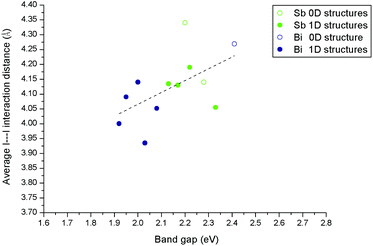 | ||
| Fig. 12 Effect of connectivity and dimensionality of the hybrid material anionic component, as measured through the length of weak I⋯I interactions, on band gap energy. | ||
A degree of correlation is observed with dimensionality in that 1D structures tend to have a smaller band gap than 0D; this is similar to the trends seen for lead halide systems which span a much larger dimensionality range.46,52
There is also a tendency towards a reduction in the band gap energy associated with a reduction in the average I⋯I interaction distance. This average I⋯I interaction distance can be taken as a measure of the degree and strength of connectivity between the anionic “network” elements of each structure. Overall smaller band gaps in hybrid bismuth and antimony iodides can be associated with both increased inorganic anion dimensionality and reduced distances between these units.
Conclusions
In summary, five new iodobismuthate and nine new iodoantimonate hybrid materials have been synthesised and structurally characterised. Templated by cationic 1,3-dimethyl-2-oxo-2,3-dihydropyrimidium, 4-methylmorpholium, 1,4-dipiperazinium, 1-methyl-1,4-dipiperazinium, 1,4-dimethyl-1,4-dipiperazinium, 1-ethyl-2-methylbenzimidazolium and 1,4-diazabicyclo[2.2.2]octan-diium ions the hybrid structures contain a number of structural anionic motifs including [MI4]n−(M = Sb, Bi), [M4I16]4−(M = Sb, Bi), [Sb6I22]4−, and a previously unseen motif of mixed [Bi2I10]4− and [BiI6]3− units exhibited in structure XIII. Also, novel in situ alkylation reaction mechanisms, as demonstrated in the hydrothermal synthesis of structures I, II, X and XI, was found to be valuable and could be further utilised in this area to explore the creation of other new templating species to yield more hybrid materials.Thermal analysis of the materials indicated the point of onset of major degradation of each hybrid material (or mixed phase) to occur in the range of 175–280 °C; with the iodobismuthate structures exhibiting increased thermal stability over their iodoantimonate counterparts. Band gap estimates for the structures were determined to range from 2.03–2.33 eV; with an expected decrease in band gap energy for isomorphic materials (I → II, X → XI) measured transitioning from antimony-iodide to bismuth-iodide based structures. Although these values are too high to be considered to compete in single junction cell architecture designs their applicability for tandem cell architectures could be considered.
Work to isolate crystals from the mixed phases for further analysis is underway; with a particular interest in comparing the 1,4-dimethyl-1,4-dipiperazinium templated polymorphic structures (VII and VIII) to observe the effect of structural change on the physical properties of the hybrid materials. The structures described here work towards building a deeper understanding of an expanding field of alternative hybrid materials in the areas of iodoantimonate and iodobismuthate chemistry. If low band gap materials (Eg ∼ 1.5 eV) suitable for solar cell absorber layers are to be found then it is likely that new materials with 2D, and ideally 3D, connectivity will be targets. However materials with lower structural dimensionality (0D or 1D) but short I⋯I interactions between inorganic units should also be of interest – particularly for applications that require larger band gaps between 1.8 and 2.5 eV.
Crystallographic data
Crystal data for I
C6H9N2OSbI4, M = 754.52, monoclinic, space group P21/c, a = 10.5506(4), b = 7.6299(3), c = 19.9962(7) Å, β = 95.336(3)°, V = 1600.63(10) Å3, Z = 4, crystal size: 0.305 × 0.080 × 0.034 mm, T = 149.9(4) K, ρcalc = 3.131 g cm−3, μ = 9.418 mm−1, 4798 reflections (4798 unique reflections), 127 parameters, 0 restraints, R1 (all data) = 0.0616, wR2 (all data) = 0.0768, GooF = 1.048, further details available from CCDC entry 1580940.†Crystal data for II
C6H9N2OBiI4, M = 841.75, monoclinic, space group P21/c, a = 10.6424(3), b = 7.6380(2), c = 20.0271(5) Å, β = 94.986(2)°, V = 1621.78(7) Å3, Z = 4, crystal size: 0.493 × 0.134 × 0.097 mm, T = 150.2(10) K, ρcalc = 3.447 g cm−3, μ = 18.465 mm−1, 5140 reflections (5140 unique reflections), 128 parameters, 0 restraints, R1 (all data) = 0.0454, wR2 (all data) = 0.0740, GooF = 1.122, further details available from CCDC entry 1580941.†Crystal data for III
C20H48N4O4Sb6I22, M = 3931.02, triclinic, space group P![[1 with combining macron]](https://www.rsc.org/images/entities/char_0031_0304.gif) , a = 11.3253(7), b = 13.0042(7), c = 15.2847(7) Å, α = 69.645(4)°, β = 69.877(5)°, γ = 64.496(6)°, V = 1853.97(17) Å3, Z = 2, crystal size: 0.376 × 0.235 × 0.175 mm, T = 150.01(10) K, ρcalc = 3.521 g cm−3, μ = 11.340 mm−1, 11
, a = 11.3253(7), b = 13.0042(7), c = 15.2847(7) Å, α = 69.645(4)°, β = 69.877(5)°, γ = 64.496(6)°, V = 1853.97(17) Å3, Z = 2, crystal size: 0.376 × 0.235 × 0.175 mm, T = 150.01(10) K, ρcalc = 3.521 g cm−3, μ = 11.340 mm−1, 11![[thin space (1/6-em)]](https://www.rsc.org/images/entities/char_2009.gif) 292 reflections (11
292 reflections (11![[thin space (1/6-em)]](https://www.rsc.org/images/entities/char_2009.gif) 292 unique reflections), 254 parameters, 0 restraints, R1 (all data) = 0.0488, wR2(all data) = 0.0633, GooF = 1.044, further details available from CCDC entry 1580942.†
292 unique reflections), 254 parameters, 0 restraints, R1 (all data) = 0.0488, wR2(all data) = 0.0633, GooF = 1.044, further details available from CCDC entry 1580942.†
Crystal data for IV
C20H48N4O4Bi4I16, M = 3275.02, orthorhombic, space group Pbca, a = 12.7627(3), b = 20.7207(6), c = 22.7427(6) Å, V = 6014.35(3) Å3, Z = 4, crystal size: 0.248 × 0.222 × 0.144 mm, T = 150.01(10) K, ρcalc = 3.617 g cm−3, μ = 19.909 mm−1, 9856 reflections (9856 unique reflections), 218 parameters, 0 restraints, R1 (all data) = 0.0416, wR2 (all data) = 0.0483, GooF = 1.107, further details available from CCDC entry 1580943.†Crystal data for V
C4H20N2O4Sb2I8, M = 1418.95, monoclinic, space group P21/c, a = 7.3391(2), b = 13.0022(5), c = 13.8121(4) Å, β = 94.550(3)°, V = 1313.86(7) Å3, Z = 4, crystal size: 0.382 × 0.121 × 0.082 mm, T = 150.00(10) K, ρcalc = 3.587 g cm−3, μ = 11.464 mm−1, 4084 reflections (4084 unique reflections), 91 parameters, 0 restraints, R1 (all data) = 0.0359, wR2 (all data) = 0.0470, GooF = 1.023, further details available from CCDC entry 1580944.†Crystal data for VI
C5H20N2O3Sb2I8, M = 1414.96, monoclinic, space group P21/c, a = 7.5306(2), b = 12.9539(4), c = 13.6147(4) Å, β = 96.086(3)°, V = 1320.64(7) Å3, Z = 4, crystal size: 0.346 × 0.0.215 × 0.137 mm, T = 150.01(10) K, ρcalc = 3.556 g cm−3, μ = 11.401 mm−1, 4034 reflections (4034 unique reflections), 110 parameters, 0 restraints, R1 (all data) = 0.0472, wR2 (all data) = 0.0711, GooF = 1.036, further details available from CCDC entry 1580945.†Crystal data for VII
C6H20N2O2Sb2I8, M = 1410.97, monoclinic, space group P21/c, a = 7.7213(2), b = 12.8027(3), c = 13.4527(3) Å, β = 97.377(2)°, V = 1318.84(5) Å3, Z = 4, crystal size: 0.280 × 0.218 × 0.179 mm, T = 149.99(10) K, ρcalc = 3.553 g cm−3, μ = 11.414 mm−1, 3513 reflections (3513 unique reflections), 92 parameters, 0 restraints, R1 (all data) = 0.0328, wR2 (all data) = 0.0563, GooF = 1.061, further details available from CCDC entry 1580946.†Crystal data for VIII
C6H20N2O2Sb2I8, M = 1410.97, monoclinic, space group P21/c, a = 7.5751(2), b = 12.1020(3), c = 14.5071(4) Å, β = 92.630(3)°, V = 1328.52(6) Å3, Z = 2, crystal size: 0.447 × 0.199 × 0.165 mm, T = 150.00(10) K, ρcalc = 3.527 g cm−3, μ = 11.331 mm−1, 4088 reflections (4088 unique reflections), 97 parameters, 0 restraints, R1 (all data) = 0.0367, wR2 (all data) = 0.0522, GooF = 1.131, further details available from CCDC entry 1580947.†Crystal data for IX
C12H20N4O2Sb4I16, M = 2769.79, monoclinic, space group P21/n, a = 11.5391(3), b = 11.8717(4), c = 19.1648(5) Å, β = 93.705(3)°, V = 2619.87(13) Å3, Z = 4, crystal size: 0.293 × 0.242 × 0.193 mm, T = 150.00(10) K, ρcalc = 3.531 g cm−3, μ = 11.486 mm−1, 8103 reflections (8103 unique reflections), 178 parameters, 0 restraints, R1 (all data) = 0.0472, wR2 (all data) = 0.0578, GooF = 1.090, further details available from CCDC entry 1580948.†Crystal data for X
C10H13N2SbI4, M = 790.58, monoclinic, space group P21/n, a = 7.5877(3), b = 17.7055(8), c = 13.2578(6) Å, β = 94.309(4)°, V = 1776.07(13) Å3, Z = 4, crystal size: 0.398 × 0.175 × 0.090 mm, T = 149.95(13) K, ρcalc = 2.957 g cm−3, μ = 8.489 mm−1, 3104 reflections (3104 unique reflections), 266 parameters, 272 restraints, R1 (all data) = 0.0760, wR2 (all data) = 0.0927, GooF = 1.197, further details available from CCDC entry 1580949.†Crystal data for XI
C10H13N2BiI4, M = 877.81, monoclinic, space group C2/c, a = 13.3133(4), b = 17.7312(4), c = 7.6344(2) Å, β = 93.450(2)°, V = 1798.92(8) Å3, Z = 4, crystal size: 0.143 × 0.120 × 0.0.079 mm, T = 150.00(10) K, ρcalc = 3.237 g cm−3, μ = 16.650 mm−1, 2049 reflections (2049 unique reflections), 123 parameters, 96 restraints, R1 (all data) = 0.0214, wR2 (all data) = 0.0435, GooF = 1.083, further details available from CCDC entry 1580950.†Crystal data for XII
C12H32N4O2Sb4I16, M = 2781.88, triclinic, space group P![[1 with combining macron]](https://www.rsc.org/images/entities/char_0031_0304.gif) , a = 10.8634(3), b = 10.8965(3), c = 11.2911(3) Å, α = 91.999(2)°, β = 109.691(2)°, γ = 95.086(2)°, V = 1250.46(6) Å3, Z = 1, crystal size: 0.392 × 0.325 × 0.324 mm, T = 150.0(2) K, ρcalc = 3.694 g cm−3, μ = 12.033 mm−1, 7862 reflections (4290 unique reflections), 178 parameters, 0 restraints, R1 (all data) = 0.0314, wR2 (all data) = 0.0602, GooF = 1.181, further details available from CCDC entry 1580951.†
, a = 10.8634(3), b = 10.8965(3), c = 11.2911(3) Å, α = 91.999(2)°, β = 109.691(2)°, γ = 95.086(2)°, V = 1250.46(6) Å3, Z = 1, crystal size: 0.392 × 0.325 × 0.324 mm, T = 150.0(2) K, ρcalc = 3.694 g cm−3, μ = 12.033 mm−1, 7862 reflections (4290 unique reflections), 178 parameters, 0 restraints, R1 (all data) = 0.0314, wR2 (all data) = 0.0602, GooF = 1.181, further details available from CCDC entry 1580951.†
Crystal data for XIII
C60H156N20O8Bi8I44, M = 8541.66, orthorhombic, space group Pbam, a = 31.9562(6), b = 15.8622(4), c = 8.6164(2) Å, V = 4367.62(17) Å3, Z = 8, crystal size: 0.363 × 0.100 × 0.0.077 mm, T = 150.00(10) K, ρcalc = 3.247 g cm−3, μ = 15.843 mm−1, 7058 reflections (7058 unique reflections), 192 parameters, 0 restraints, R1 (all data) = 0.0480, wR2 (all data) = 0.0699, GooF = 1.164, further details available from CCDC entry 1580952.†Crystal data for XIV
C12H32N4O2Bi4I16, M = 3130.03, monoclinic, space group P21/c, a = 11.0086(3), b = 15.4751(3), c = 15.3455(4) Å, β = 103.001(2)°, V = 2547.23(11) Å3, Z = 2, crystal size: 0.312 × 0.295 × 0.0.215 mm, T = 150.00(10) K, ρcalc = 4.082 g cm−3, μ = 23.491 mm−1, 7829 reflections (7829 unique reflections), 178 parameters, 0 restraints, R1 (all data) = 0.0474, wR2 (all data) = 0.0666, GooF = 1.042, further details available from CCDC entry 1580953.†Single crystal X-ray diffraction data collection instrumentation
Single crystal data for structures I–X and XII–XIV were collected on an Agilent Xcalibur four-circle diffractometer equipped with a fine-focus (Mokα) X-ray source and EosS2 CCD plate detector. Single crystal data for structure XI was collected on an Agilent SuperNova Dual four-circle diffractometer equipped with dual fine-focus (Mokα and Cukα) X-ray sources and EosS2 CCD plate detector.Conflicts of interest
There are no conflicts to declare.Acknowledgements
The authors would like to thank Dr Mary F. Mahon for assistance with the single crystal X-ray crystallography. AJD would like to thank EPSRC for DTA studentship support.References
- S. A. Adonin, M. N. Sokolov and V. P. Fedin, Coord. Chem. Rev., 2016, 312, 1–21 CrossRef CAS.
- N. Mercier, N. Louvain and W. H. Bi, CrystEngComm, 2009, 11, 720–734 RSC.
- S. Pohl, R. Lotz, W. Saak and D. Haase, Angew. Chem., Int. Ed. Engl., 1989, 28, 344–347 CrossRef.
- G. A. Fisher and N. C. Norman, Adv. Inorg. Chem., 1994, 41, 233–272 CrossRef CAS.
- M. Weclawik, A. Gagor, R. Jakubas, A. Piecha-Bisiorek, W. Medycki, J. Baran, P. Zielinski and M. Galazka, Inorg. Chem. Front., 2016, 3, 1306–1316 RSC.
- A. M. Goforth, L. Peterson, M. D. Smith and H. C. zur Loye, J. Solid State Chem., 2005, 178, 3529–3540 CrossRef CAS.
- W. H. Bi and N. Mercier, Chem. Commun., 2008, 5743–5745 RSC.
- A. M. Goforth, J. R. Gardinier, M. D. Smith, L. Peterson and H. C. Z. Loye, Inorg. Chem. Commun., 2005, 8, 684–688 CrossRef CAS.
- C. Hrizi, A. Samet, Y. Abid, S. Chaabouni, M. Fliyou and A. Koumina, J. Mol. Struct., 2011, 992, 96–101 CrossRef CAS.
- A. Samet, A. Ben Ahmed, A. Mlayah, H. Boughzala, E. K. Hlil and Y. Abid, J. Mol. Struct., 2010, 977, 72–77 CrossRef CAS.
- A. M. Goforth, M. A. Tershansy, M. D. Smith, L. Peterson, J. G. Kelley, W. J. I. DeBenedetti and H. C. zur Loye, J. Am. Chem. Soc., 2011, 133, 603–612 CrossRef CAS PubMed.
- C. Feldmann, J. Solid State Chem., 2003, 172, 53–58 CrossRef CAS.
- J. Heine, Dalton Trans., 2015, 44, 10069–10077 RSC.
- H. Krautscheid, Z. Anorg. Allg. Chem., 1995, 621, 2049–2054 CrossRef CAS.
- H. Krautscheid, Z. Anorg. Allg. Chem., 1999, 625, 192–194 CrossRef CAS.
- S. A. Adonin, E. V. Peresypkina, M. N. Sokolov and V. P. Fedin, Russ. J. Coord. Chem., 2014, 40, 867–870 CrossRef CAS.
- H. Krautscheid, Z. Anorg. Allg. Chem., 1994, 620, 1559–1564 CrossRef.
- K. Y. Monakhov, C. Gourlaouen, R. Pattacini and P. Braunstein, Inorg. Chem., 2012, 51, 1562–1568 CrossRef CAS PubMed.
- V. V. Sharutin, I. V. Egorova, N. N. Klepikov, E. A. Boyarkina and O. K. Sharutina, Russ. J. Inorg. Chem., 2009, 54, 1768–1778 CrossRef.
- A. Okrut and C. Feldmann, Z. Anorg. Allg. Chem., 2006, 632, 409–412 CrossRef CAS.
- S. A. Adonin, M. N. Sokolov, P. A. Abramov, S. G. Kozlova, D. P. Pishchur, L. A. Sheludyakova and V. P. Fedin, Inorg. Chim. Acta, 2014, 419, 19–25 CrossRef CAS.
- D. B. Mitzi and P. Brock, Inorg. Chem., 2001, 40, 2096–2104 CrossRef CAS PubMed.
- G. A. Mousdis, G. C. Papavassiliou, A. Terzis and C. P. Raptopoulou, Z. Naturforsch., B: J. Chem. Sci., 1998, 53, 927–931 CAS.
- C. Hrizi, N. Chaari, Y. Abid, N. Chniba-Boudjada and S. Chaabouni, Polyhedron, 2012, 46, 41–46 CrossRef CAS.
- S. Chaabouni, S. Kamoun and J. Jaud, J. Chem. Crystallogr., 1997, 27, 527–531 CrossRef CAS.
- N. A. Yelovik, A. V. Mironov, M. A. Bykov, A. N. Kuznetsov, A. V. Grigorieva, Z. Wei, E. V. Dikarev and A. V. Shevelkov, Inorg. Chem., 2016, 55, 4132–4140 CrossRef CAS PubMed.
- A. Gagor, M. Weclawik, B. Bondzior and R. Jakubas, CrystEngComm, 2015, 17, 3286–3296 RSC.
- D. B. Mitzi, Inorg. Chem., 2000, 39, 6107–6113 CrossRef CAS PubMed.
- C. J. Carmalt, L. J. Farrugia and N. C. Norman, Z. Anorg. Allg. Chem., 1995, 621, 47–56 CrossRef CAS.
- P. Szklarz, A. Pietraszko, R. Jakubas, G. Bator, P. Zielinski and M. Galazka, J. Phys.: Condens. Matter, 2008, 20, 12 CrossRef.
- M. Bujak and J. Zaleski, J. Mol. Struct., 2003, 647, 121–128 CrossRef CAS.
- A. Gagor, G. Banach, M. Weclawik, A. Piecha-Bisiorek and R. Jakubas, Dalton Trans., 2017, 46, 16605–16614 RSC.
- S. Pohl, R. Lotz, D. Haase and W. Saak, Z. Naturforsch., B: J. Chem. Sci., 1988, 43, 1144–1150 CAS.
- C. J. Carmalt, N. C. Norman and L. J. Farrugia, Polyhedron, 1994, 13, 1655–1658 CrossRef.
- G. Volonakis, M. R. Filip, A. A. Haghighirad, N. Sakai, B. Wenger, H. J. Snaith and F. Giustino, J. Phys. Chem. Lett., 2016, 7, 1254–1259 CrossRef CAS PubMed.
- W. Medycki, K. Holderna-Natkaniec, J. Swiergiel and R. Jakubas, Solid State Nucl. Magn. Reson., 2003, 24, 209–217 CrossRef CAS PubMed.
- W. H. Bi, N. Leblanc, N. Mercier, P. Auban-Senzier and C. Pasquier, Chem. Mater., 2009, 21, 4099–4101 CrossRef CAS.
- K. Gesi, M. Iwata and Y. Ishibashi, J. Phys. Soc. Jpn., 1995, 64, 2650–2655 CrossRef CAS.
- R. Jakubas, A. Piecha, A. Pietraszko and G. Bator, Phys. Rev. B: Condens. Matter Mater. Phys., 2005, 72, 8 CrossRef.
- Research cell efficiency records, https://www.nrel.gov/pv/assets/images/efficiency-chart.png (accessed October 2017).
- A. M. Ganose, C. N. Savory and D. O. Scanlon, J. Phys. Chem. Lett., 2015, 6, 4594–4598 CrossRef CAS PubMed.
- Q. D. Tai, P. You, H. Q. Sang, Z. K. Liu, C. L. Hu, H. L. W. Chan and F. Yan, Nat. Commun., 2016, 7, 8 Search PubMed.
- N. K. Noel, S. D. Stranks, A. Abate, C. Wehrenfennig, S. Guarnera, A. A. Haghighirad, A. Sadhanala, G. E. Eperon, S. K. Pathak, M. B. Johnston, A. Petrozza, L. M. Herz and H. J. Snaith, Energy Environ. Sci., 2014, 7, 3061–3068 CAS.
- S. F. Hoefler, G. Trimmel and T. Rath, Monatsh. Chem., 2017, 148, 795–826 CrossRef CAS PubMed.
- X. P. Wang, T. Yan, Y. Li, Y. X. Liu, B. Du, H. M. Ma and Q. Wei, Sci. Rep., 2015, 5, 8 Search PubMed.
- L. M. Wu, X. T. Wu and L. Chen, Coord. Chem. Rev., 2009, 253, 2787–2804 CrossRef CAS.
- J. Laane and P. W. Jagodzinski, Inorg. Chem., 1980, 19, 44–49 CrossRef CAS.
- H. L. Sheu and J. Laane, Inorg. Chem., 2013, 52, 4244–4249 CrossRef CAS PubMed.
- A. J. Dennington and M. T. Weller, Dalton Trans., 2016, 45, 17974–17979 RSC.
- V. V. Sharutin, A. P. Pakusina, O. K. Sharutina, O. A. Kovaleva, A. V. Gerasimenko and M. A. Pushilin, Russ. J. Coord. Chem., 2004, 30, 541–549 CrossRef CAS.
- C. Hrizi, A. Trigui, Y. Abid, N. Chniba-Boudjada, P. Bordet and S. Chaabouni, J. Solid State Chem., 2011, 184, 3336–3344 CrossRef CAS.
- M. E. Kamminga, G. A. de Wijs, R. W. A. Havenith, G. R. Blake and T. T. M. Palstra, Inorg. Chem., 2017, 56, 8408–8414 CrossRef CAS PubMed.
Footnote |
| † Electronic supplementary information (ESI) available: UV-vis spectra and thermogravimetric data. CCDC 1580940–1580953. For ESI and crystallographic data in CIF or other electronic format see DOI: 10.1039/c7dt04280a |
| This journal is © The Royal Society of Chemistry 2018 |

