
 Open Access Article
 This Open Access Article is licensed under a
 Creative Commons Attribution 3.0 Unported Licence
Dry reforming of methane over Co–Mo/Al2O3 catalyst under low microwave power irradiation†
Hoang M.
Nguyen
 a,
Gia Hung
Pham
*a,
Ran
Ran
a,
Robert
Vagnoni
b,
Vishnu
Pareek
a and
Shaomin
Liu
*a
a,
Gia Hung
Pham
*a,
Ran
Ran
a,
Robert
Vagnoni
b,
Vishnu
Pareek
a and
Shaomin
Liu
*a
aDepartment of Chemical Engineering, Curtin University, GPO Box U1987, Perth, Western Australia 6845, Australia. E-mail: G.Pham@curtin.edu.au; Shaomin.Liu@curtin.edu.au
bEco Technol Co., Pty Ltd, Perth, Western Australia 6009, Australia
First published on 11th September 2018
Abstract
In this work, microwave (MW) irradiation was used to activate Co/Al2O3, Mo/Al2O3, and Co–Mo/Al2O3 catalysts for dry reforming of methane (DRM) reactions. Experimental results indicate that single metallic catalysts of either Co or Mo are inactive for DRM under all the tested conditions due to their limited MW-absorbing ability. In contrast, Co–Mo bimetallic catalysts supported by Al2O3 exhibit high catalytic activity due to the formation of a magnetodielectric Co0.82Mo0.18 alloy, which plays the dual role of a good MW acceptor and the provider of active centers for the DRM reaction. The MW power level required to activate such bimetallic catalysts for DRM is significantly dependent on the molar ratio between Co and Mo. The CoMo2 catalyst (with a molar ratio of 2.0 Co to 1.0 Mo) supported on Al2O3 exhibits the best catalytic performance, converting 80% CH4 and 93% CO2 to syngas at a ratio of H2/CO of 0.80 at the total volumetric hourly space velocity (VHSV) of 10 L g−1 h−1 and MW power of 200 W. As compared to the reported C-based catalysts, the Co–Mo/Al2O3 catalyst delivers more favorable stability over 16 time-on-stream (TOS) by virtue of its intrinsic ability to absorb MW without the inclusion of auxiliary MW acceptors.
1. Introduction
A growing share of the world's natural gas reserves is located in remote areas like deep offshore, of which relatively bigger gas reserves can be harnessed by liquefying the natural gas (LNG) for transportation using tanks. However, most of the small gas reserves are stranded: in the case of associated production (i.e., gas produced with crude oil), the natural gas has to be re-injected.1–3 This not only results in the loss of income but also pollutes the environment due to gas leakage to air. Because of this, there is a sustained demand for small-to-medium-sized gas-to-liquid (GTL) plants on floating production, storage, and offloading vessels (FPSOVs). These are particularly important for small stranded gas reserves, where the gas pipeline option is completely uneconomical. The production of syngas is the first step in a GTL plant, which must have the minimal weight to be suitable for FPSOVs.Among the three methane reforming methods (dry, steam, and autothermal), dry reforming of methane (DRM) has attracted increased attention due to the conversion of two greenhouse gases (CH4, CO2) to produce syngas (H2 and CO), which is used as the feed for Fischer–Tropsch synthesis.4 The primary challenge in the applications of the DRM process is the thermodynamic barrier caused by the high thermal stability of CH4 and CO2 requiring higher temperatures (700–1200 °C) for the DRM operation to achieve expected conversions.5 Most of the current studies on DRM have used conventional electric heating methods,6 which not only consume considerable energy but also require heavy heat exchanger tubes, complicating the operation of a reformer system in FPSOV vessels.2 Microwave (MW) is known to be an energy-saving heating method, which can be used to reduce energy consumption for DRM processes.7 Other advantages of using the MW heating system are greater control over the heating process, quick start and stop facility, and high level of safety and automation.8 Prominently, DRM heated by MW irradiation allows to reduce the number of equipment, which favors the riser and mooring systems to produce syngas and imparts greater flexibility in controlling the reactor size through which a lightweight reformer can be fabricated, particularly for FPSOVs. MW plasma DRM reaction without a catalyst has been investigated by several researchers.9–11 However, plasma processes have low energy efficiency owing to the higher MW power required to stabilize plasma.12 In order to effectively reduce the energy consumption, a combination of catalyst and MW irradiation is considered to be a promising approach. The primary idea of combining MW and heterogeneous catalysis is to exert volumetric controllable electromagnetic action on the catalyst–reagents system. This action alters the state of the reaction system and leads to a considerable change in the apparent thermodynamics of the gas-phase reactions, resulting in higher conversion values at lesser extreme conditions.13 A catalytic DRM process under MW irradiation can compete with currently well-established steam-based methane reforming processes in terms of conversion amounts and energy consumption.14 All the reported works on DRM under MW heating simply used carbon-based materials as the catalyst15–19 since carbon-based materials are good MW absorbers. However, the catalytic activity and stability of carbon-based catalysts deteriorate significantly due to carbon loss.20 Consequently, there is a room for the development of catalysts for DRM heated by MW irradiation.
Co is known to be a good catalyst/promoter of reforming reactions.21–24 Coke deposition, which leads to catalyst deactivation, is one of the main constraints of Co-based catalysts.25 Mo is considered as an environmentally friendly and cost-effective catalyst with longstanding stability toward hydrogenating reactions.26 Hence, the addition of Mo in the Co/Al2O3 structure suppresses coke deposition during the reforming process.27 In the literature, Co/Al2O3 (ref. 28 and 29) and Mo/Al2O3 (ref. 30) catalysts exhibit catalytic activity for DRM under conventional heating. Meanwhile, Co–Mo/Al2O3 has been extensively investigated as an efficient catalyst for several processes such as hydrodesulfurization,31–34 hydrotreatment,35,36 syngas conversion,37 and natural gas decomposition.27 Nonetheless, a highly efficient Co–Mo/Al2O3 catalyst for DRM, particularly under MW irradiation, has not been reported. The main objective of this work is to explore the catalytic activity of a series of Co–Mo/Al2O3 catalysts for DRM under MW irradiation. The mechanism of the activation of Co–Mo/Al2O3 catalyst for DRM reaction under MW irradiation is explored. The correlation between the molar ratios of Co and Mo and the irradiated MW power levels on the catalytic activity and stability is also attempted.
2. Experimental
2.1. Catalyst preparation
The list of chemicals used in this study is shown in the ESI† (Table S1). Quartz tube reactors were purchased from Monash Scientific Glass Blowing Services, Australia. In this study, monometallic catalysts (Cox/Al2O3, Moy/Al2O3) with the molar fraction of each metallic component from 0.1 to 0.6 were prepared by the conventional wet co-impregnation method. Co–Mo/Al2O3 bimetallic catalysts (molar fraction of Mo fixed at 0.1) with different Co/Mo molar ratios of 0.5 (CoMo0.5), 1.0 (CoMo1), 1.5 (CoMo1.5), 2.0 (CoMo2), and 2.5 (CoMo2.5) were separately prepared. Cobalt(II) nitrate and ammonium molybdate tetrahydrate were accurately weighed and properly dissolved in deionized water. The solution was stirred for 4 h. Al2O3 spheres (dried at 100 °C overnight to eliminate humidity) were then added into the solution and stirred for 2 h at room temperature. The precursor mixture was slowly heated up to 60 °C at a heating rate of 1 °C min−1 and maintained at this temperature for 12 h in the furnace. The sample was then ramped up to 250 °C for 4 h before ramping up to 600 °C and maintained at this temperature for 6 h at a heating rate of 1 °C min−1.2.2. Catalyst characterization
Powder X-ray diffraction (XRD) analysis of the catalysts was performed using the Empyrean X-ray with Cu Kα radiation (λ = 0.15418 nm) in the scan range of 10–90° with a scanning step size of 0.01° and time of 2 s. Rietveld refinement analysis was performed by using the FullProf Suite program. N2 adsorption and Brunauer–Emmett–Teller (BET) measurements were conducted using the Tristar II 3020 equipment. The samples were degassed at 250 °C for 16 h prior to running with liquid N2. Temperature-programmed reduction (H2-TPR) experiments were conducted by using the ChemBET 3000 equipment. For each analysis, 0.1 g of the catalyst powder was subsequently loaded into a quartz cell. The sample was outgassed at 250 °C for 4 h with flowing N2 through the cell to eliminate contaminants on the surface of the catalyst samples. A gas mixture of 5% H2/N2 at a total flow rate of 20 ml min−1 was induced through the quartz cell. The reduction temperature was increased from room temperature to 950 °C. The morphology of the fresh and spent catalysts were characterized by field emission scanning electron microscopy (FESEM, Zeiss NEON 40 EsB CrossBeam) equipped with energy-dispersive X-ray spectroscopy (EDX) at an acceleration voltage of 20 keV, yielding compositional and atomic dispersion analyses. Moreover, scanning transmission electron microscopy (STEM) with high-angle annular dark-field (HAADF) and bright field (BF) accompanied with the EDX detector (FEI Titan G2 80-200 TEM/STEM microscope) were employed to analyze the catalyst structure. All the STEM-EDX samples were deposited by immersing onto a copper support grid. In this work, a superconducting quantum interference device (SQUID), Quantum Design MPMS-7, was employed to evaluate the magnetic properties of the reduced catalysts with a maximal applied field of 20 kOe.2.3. Catalytic activity measurement
The DRM catalytic activity of all the prepared catalysts were subsequently measured at atmospheric pressure using a commercial MW reactor system (Alter, SM 1150T, Canada). The schematic diagram of the DRM heated by a MW system is shown in the ESI† (Fig. S1). The output power of the MW generator can be flexibly set between 0 and 3000 W at a fixed frequency of 2.45 GHz. Two directional couplers were inserted into the microwave guide system to monitor the forwarded/reflected MW power. Prior to the DRM reaction, the calcined catalysts were subsequently reduced in a tube furnace with the mixture of 10% H2/N2. N2 was first introduced through the tube furnace at 600 °C for 1 h to remove moisture and impurities in the catalysts. A gas mixture of 10% H2/N2 at a total flow rate of 10 mL min−1 was injected through the furnace for 6 h at 600 °C to reduce the catalyst samples. After reduction, the catalyst samples were maintained in an inert condition with N2 (10 mL min−1) to cool down to room temperature to prevent catalyst re-oxidation. The catalyst bed inside the quartz tube reactor (120 × 25 × 1.68 mm) was loaded with quartz wool and 4 g of fresh catalyst. The total feed flow rate fixed for all the tests was controlled at volumetric hourly space velocity (VHSV) of 10 L g−1 h−1 with CO2/CH4 = 1.0. For each catalytic activity measurement, the MW power was gradually increased from 50 to 1000 W at 50 W intervals. In the downstream section, the product stream was passed through a water trap to separate condensable products. The effluent gas was analyzed by gas chromatography (Agilent 7890A) equipped with two columns: (i) HP-5 connected to a MS detector for analyzing C2+ compounds and (ii) TDX 01 connected to a TCD detector for H2, CO, CO2, N2, and CH4 quantitative analyses. The analyses were performed after the DRM reaction was established and each analysis was repeated three times. Additional details about the reactant conversion and product selectivity calculation can be found in the ESI.†3. Results and discussion
3.1. Catalytic activity
The reactant gas conversions of all the fresh catalyst samples were collected under steady-state conditions; the results are shown in Fig. 1. | ||
| Fig. 1 CH4 conversion (a) and CO2 conversions (b) of DRM reaction for all the catalysts over MW irradiation at different MW power levels. Reaction parameters: CH4/CO2 = 1, VHSV = 10 L g−1 h−1. | ||
It is noteworthy that either of the monometallic catalyst Co or Mo supported by Al2O3 was inactive for DRM under MW heating. Hence, no reactant conversions or syngas selectivity was detected at all the tested MW power levels from 50 to 1000 W. In contrast, the bimetallic catalysts of Co–Mo/Al2O3 started to convert approximately 35% CH4 and 47% CO2 for CoMo0.5 and MW power of 500 W. There is another observation that the required minimum MW power level to activate the bimetallic catalysts declines with an increase in the Co loading up to Co/Mo of 2. The bimetallic catalysts of CoMo2 and CoMo2.5 could be activated at far lower MW power (200 W) than those with CoMo1 (400 W) and CoMo1.5 (300 W), respectively. Furthermore, a higher Co/Mo molar ratio value resulted in larger reactant conversion and syngas selectivity. However, both CH4 or CO2 conversions and H2 or CO selectivity increased with the Co/Mo loading increase up to 2. A further addition of Co such as Co/Mo ratio of 2.5 results in a reversible effect, possibly due to the fact that the excessive amount of Co promotes the formation of inactive phases to suppress surface active sites that prevent the incident MW wave adsorption, and therefore, lowering the activity. Such influences will be discussed shortly. Notably, the conversion of CO2 was higher than that of CH4 and the selectivity of CO was also higher than that of H2 for all the tested cases. Moreover, both CH4 and CO2 conversion increases with the MW power (Fig. 1a and b). In contrast, there are two opposite trends of H2 and CO selectivity variation toward the employed MW power levels (Fig. 2a and b). Moreover, the selectivity of H2 gradually declined, while that of CO sharply increased with increasing MW power, which also leads to a decrease in the syngas ratio of H2/CO (Fig. S2†).
 | ||
| Fig. 2 H2 selectivity (a) and CO selectivity (b) of DRM reaction for all the catalysts over MW irradiation at different MW power levels. Reaction parameters: CH4/CO2 = 1, VHSV = 10 L g−1 h−1. | ||
This observation reveals that in addition to the major DRM reaction (eqn (1)), the other reactions such as carbon deposition (eqn (2)), Boudouard reactions (eqn (3)), and reversed water gas shift (RWGS) (eqn (4)) would simultaneously occur.
| CH4 + CO2 ↔ 2H2 + 2CO | (1) |
| CH4 ↔ C + 2H2 | (2) |
| CO2 + C ↔ 2CO | (3) |
| CO2 + H2 ↔ CO + H2O | (4) |
Numerous papers in the literature have reported the observation of water as a byproduct of the DRM reaction.38,39 In this work, a marginal amount of water production was observed (Fig. S1†), confirming the occurrence of the RWGS reaction (eqn (4)). The side reactions such as eqn (3) and (4) are highly endothermic,40 and therefore, the H2/CO ratio declined as the MW power levels increased (Fig. S2†). Furthermore, it should be noted that C is a strong MW absorber;20 consequently, the Boudouard reaction (eqn (3)) would be further facilitated for C removal, suppressing the C residue (deposition) under MW irradiation. A similar observation was made by other researchers.41 The incident MW radiation creates transient electron–hole pairs on the C surface, which act as radical anions and cations, reducing CO2 molecules to generate CO. Therefore, the use of MW irradiation exhibits additional advantages: not only promoting the Boudouard reaction to produce more CO, but also reducing C deposition. However, this advantage of using MW irradiation for DRM can only be reflected in a heterogeneous catalyst system with inherent capability to absorb MW without the need of including other MW absorbers (e.g., C). Other researchers explored the catalytic performance with C (a good MW acceptor) or mixed C with more active catalysts such as Ni/Al2O3.42–44 In these catalyst systems, the maximum conversions of CH4 (>90%) and CO2 (>80%) could be obtained at a temperature above 800 °C. However, the decrease in the catalytic activity was rapidly observed in less than 1 or 2 h. The reason for such poor stability is due to the occurrence of the Boudouard reaction (eqn (3)), leading to C loss during the DRM process.20 Pt, a noble metal with high catalytic activity, was also mixed with active C for DRM under MW heating.45 As reported, the amount of C catalyst was decreased over approximately 270 min at 34 mL min−1, CH4/CO2 = 1, and MW power of 150 W. As compared to the reported C-based catalysts,43 CoMo2 showed good catalytic activity, converting 80% CH4 and 93% CO2 to the syngas ratio (H2/CO) of 0.80 at a higher total VHSV of 10 L g−1 h−1 and low MW power of 200 W. In addition to the higher catalytic activity, the bimetallic catalyst also exhibited better stability. The long-time tests of CoMo2 for DRM over 16 h time-on-stream (TOS) under MW irradiation with 3 typical MW power levels (200, 500, and 1000 W) were conducted, and the results are shown in Fig. 3. The catalytic performance of the tested bimetallic catalyst is almost constant over 16 TOS at MW power of 200 W. At higher MW power of 500 W, a minor decline in the catalytic activity was observed. However, at MW power of 1000 W, the decline in the catalytic performance was more apparent as compared to that under lower MW. The CoMo2 catalyst delivers highly stable catalytic activity owing to its intrinsic ability to absorb MW energy without the need of mixing with C in the catalyst bed, which would lead to shorter catalyst lifetime because of C loss during the DRM reaction. Pt catalyst supported by γ-Al2O3 can also be activated under MW heating for DRM at the total VHSV of 7.2 L g−1 h−1.46 Nevertheless, such a noble metallic-based catalyst is infeasible for large-scale applications47 due to high catalyst costs.
 | ||
Fig. 3 Catalytic stability of CoMo2 catalyst at three different MW power levels. Reaction parameters: CH4![[thin space (1/6-em)]](https://www.rsc.org/images/entities/char_2009.gif) :CO2 = 1, VHSV = 10 L g−1 h−1. :CO2 = 1, VHSV = 10 L g−1 h−1. | ||
Other catalysts with carbonaceous material developed by Zhu and coworkers were investigated for syngas production via DRM heated by MW (350–600 W) over Ni/CeO2 catalyst doped with Cr/Fe/Ta at total VHSV of 10.2 L g−1 h−1.48In situ grown carbonaceous materials like graphene or carbon nanotubes were cleverly used to increase the MW absorption and reaction efficiency. However, the long-term stability of the catalytic performance is still a problem due to C loss. Very recently, Gangurde and coworkers synthesized Ru-doped SrTiO3 perovskite catalysts that could also absorb MW energy for DRM.49 Nonetheless, an excessive amount of CO2 was needed to be present in the feed gas to limit C formation. This, without doubt, increases the downstream burden to separate or recycle the unreacted CO2, leading to complexities in the DRM process.13
3.2. Catalyst characterization
A series of physical analyses were performed to appraise the relationship between the catalyst structure and catalytic activity for DRM under MW irradiation. The characterization results of CoMo2 bimetallic catalyst are presented with some monometallic catalysts for comparison purposes. Fig. 4A shows the N2 absorption/desorption isotherm curves of monometallic and CoMo2 catalyst samples. As observed, the physisorption isotherm curves of both monometallic and bimetallic catalysts ascribe to type IV (Fig. 4A), which is a favorable feature for mesoporous materials with high catalytic activity for gas-phase reactions.50 Decreases in the pore size and BET surface area were observed by increasing the molar ratio of Co/Mo from 0.5 to 2.5 (Table S2†). This is due to the decrease in the alumina content per weight unit as the porous support contributing majorly toward the high surface area. It is noteworthy that the BET surface area as well as the pore size of bimetallic catalysts was insignificantly altered at low irradiated MW power levels (such as 200 W) (Table S3†), which mirrors high stability under such operating conditions. These results help to explain the conservancy of catalytic activity over 16 TOS of the bimetallic catalyst at low MW powers (Fig. 3). However, the considerable deterioration in the textural properties of bimetallic catalysts was observed at higher MW power, i.e., 1000 W, possibly due to the high-temperature sintering of metallic-based particles to form bigger particles under high MW energy heating, decreasing the catalyst's surface area. The porosity of monometallic catalysts, conversely, is unaffected by MW energy since these catalysts were inactive. | ||
| Fig. 4 N2 absorption/desorption isotherm curves (A) and TPR-H2 profiles (B) of (a) Mo/Al2O3, (b) Co/Al2O3, and (c) CoMo2 catalyst. | ||
In the meanwhile, the TPR-H2 analysis indicates the differences in the reducibility between the calcined mono- and bimetallic catalysts. Fig. 4B shows the TPR-H2 profiles of Co/Al2O3, Mo/Al2O3, and CoMo2 catalysts. The calcined Co/Al2O3 catalyst exhibits 2 H consumption peaks located at 454.1 and 630.7 °C, which are assigned to the reduction of Co3+ to Co2+ and Co2+ to Co0, respectively.51 There are also 2 distinct H consumption peaks, respectively, at 753.4 and 897.1 °C observed from the calcined Mo/Al2O3. The initial peak is attributed to the reduction of Mo6+ to Mo4+, while the latter is associated with the reduction of Mo4+ to Mo0 or the reduction of tetrahedral Mo species.52 There are also two distinct H consumption peaks, respectively, at 753.4 and 897.1 °C observed from the calcined Mo/Al2O3. The initial peak is attributed to the reduction of Mo6+ to Mo4+, while the latter is associated with the reduction in Mo4+ to Mo0 or the reduction of tetrahedral Mo species.52 The introduction of Co into monometallic Mo supported by Al2O3 at a Co/Mo molar ratio of 2 led to an improvement in catalyst reducibility. The H2 consumption peak of Co species reduction shifted from 454.1 to 397.2 °C, while that of Mo6+ was reduced from 897.1 to 757.6 °C. Moreover, by increasing the Co/Mo ratio from 0.5 to 2.5, the reduction temperature of the bimetallic catalyst samples also shifted to lower values (Fig. S4†). Therefore, in the mixture form, the synergetic effects between two metallic atoms (Co and Mo) weaken the interaction of each metallic component with the Al2O3 support, which leads to an improvement in the reducibility of the bimetallic catalyst samples. It is noteworthy that distinguishable H consumption peaks located at 551.2 °C and the small shoulder at 493.7 °C are observed for the CoMo2 catalyst (Fig. 4B). Understandably, these observed peaks are associated with the reduction in the bimetallic oxides such as CoMoO4 to a bimetallic alloy, which will be further confirmed by XRD, FESEM-EDX, and STEM-EDX. A similar observation was made by other researchers, who observed the reduction of CoMoO4 to Co2Mo3 alloy at 575 °C of Co–Mo supported on a SiO2 catalyst.53
To further verify the effects of the catalyst structure on the catalytic activity, XRD analyses of fresh and spent catalysts were performed. The results are shown in Fig. 5.
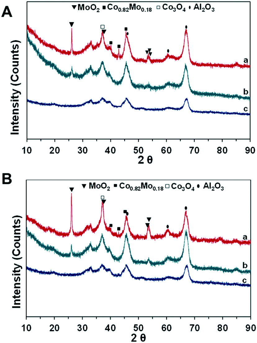 | ||
| Fig. 5 XRD of fresh (A) and spent (B) catalysts: (a) CoMo2; (b) Mo/Al2O3; (c) Co/Al2O3. Reaction parameters: 500 W, CH4:CO2 = 1, VHSV = 10 L g−1 h−1. | ||
There is fairly low crystallinity of the reduced Co/Al2O3 and Mo/Al2O3 catalysts since the broad peaks at 45.92°, 60.64°, and 67.01° (PDF 96-101-0462) can be ascribed to Al2O3 (Fig. 5A and B). The TPR-H2 profile of the calcined Co/Al2O3 catalyst indicates two different reducing peaks of Co oxides, while the XRD shows the absence of Co-based diffraction peaks. This suggests the very good dispersion of Co-based particles in the support structure, which will be further confirmed by electron microscopy analysis techniques. In the meanwhile, the previous TPR-H2 profiles of the Mo/Al2O3 catalyst indicate that the reduction of Mo-based ions was at higher temperatures (>750 °C); hence, the MoO2 phase would be still detected from the Mo/Al2O3 sample at 26.15° (PDF 96-153-9091). Noticeably, the intensity of all the diffraction peaks increased with the co-presence of Co and Mo supported on Al2O3 (Fig. 5). In particular, the improvement in the degree of crystallization is observed when the increase in the Co/Mo ratio from 0.5 to 2.5 (Fig. S5a†). The XRD patterns reveal that Co significantly interacts with the Mo species, and therefore, improved the degree of crystallization. The XRD diffraction peaks of MoO2 are at 26.15°, 37.17°, 53.22°, 53.63°, and 53.78° (PDF 96-153-9091). The previous TPR-H2 profile of CoMo2 indicates the reduction-related peak of Co3+ species at 397.2 °C; however, the diffraction peak at 36.8°, ascribed to the Co3O4 phase (PDF 96-153-8532), was visibly detected from this bimetallic catalyst (Fig. 5). This observation displays a complex dispersion of metallic components into the support structure. It is worth noting that the diffraction peaks at 40.10°, 42.91°, and 45.48° (PDF 96-152-5121), ascribed to the Co0.82Mo0.18 bimetallic alloy, are detected from the bimetallic catalysts.
Gaytan and coworkers also observed the crystal pattern of the Co0.82Mo0.18 alloy when fabricating a Co-based alloy by the electron beam melting method.54 The presence of this bimetallic alloy affirms the previous TPR-H2 profile on the prediction regarding the reduction of bimetallic oxide such as CoMoO4 to Co0.82Mo0.18 alloy within the range of temperatures from 490 to 555 °C. The presence of Co0.82Mo0.18 is very unique for a bimetallic catalyst and may be the reason for Co–Mo/Al2O3 bimetallic catalysts to be active for DRM under MW irradiation. Furthermore, the Rietveld refinement analysis result of fresh CoMo2 catalysts (Fig. 6) indicates that the cell parameters of the Co0.82Mo0.18 alloy (Table S4†) can be assigned to the space group symmetry of P63/mmc with hexagonal crystallography (a = 2.5582 Å and c = 4.2231 Å, α = β = 90°). Further, there is good matching between the XRD patterns of the CoMo2 catalyst and the calculated model, as confirmed by the graphical fitting and by the values of the agreement factor (χ2 = 1.42). After 16 h TOS of DRM reaction under MW irradiation, the crystalline structure of monometallic catalysts remained unaltered (Fig. 5B) since Co/Al2O3 or Mo/Al2O3 does not facilitate DRM under MW heating. For the spent Co–Mo/Al2O3 catalyst, the patterns of MoO2, Co0.82Mo0.18, and Co3O4 are still detected. This result evokes the stability of the crystalline structure of bimetallic catalysts under the redox environment of DRM reaction as well as MW irradiation, leading to enduring catalytic stability. Noticeably, the Co2Mo3O8 phase can be visibly identified at 17.87° and 25.29° (PDF 96-152-4069) from the spent CoMo2.5 catalyst (Fig. S5b†). The appearance of the Co2Mo3O8 phase elicits either the reaction between finely dispersed metallic Co0 and MoOx or the oxidation of Co0.82Mo0.18 in the oxygen-rich reforming environment.
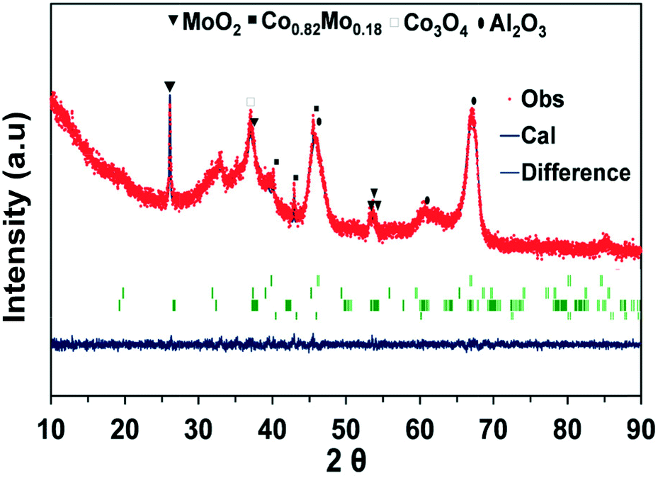 | ||
| Fig. 6 XRD patterns fitted using the Rietveld refinement method for the CoMo2 catalyst sample. χ2 = 1.12. | ||
The morphology of fresh CoMo2 characterized by FESEM (Fig. 7a1) exhibits randomly oriented particles with relatively uniform size distribution. Moreover, its FESEM-EDX analysis results (Fig. S6†) indicate the locations that contain larger atomic numbers of both Mo and Co, reflecting the presence of Co0.82Mo0.18 bimetallic alloy.
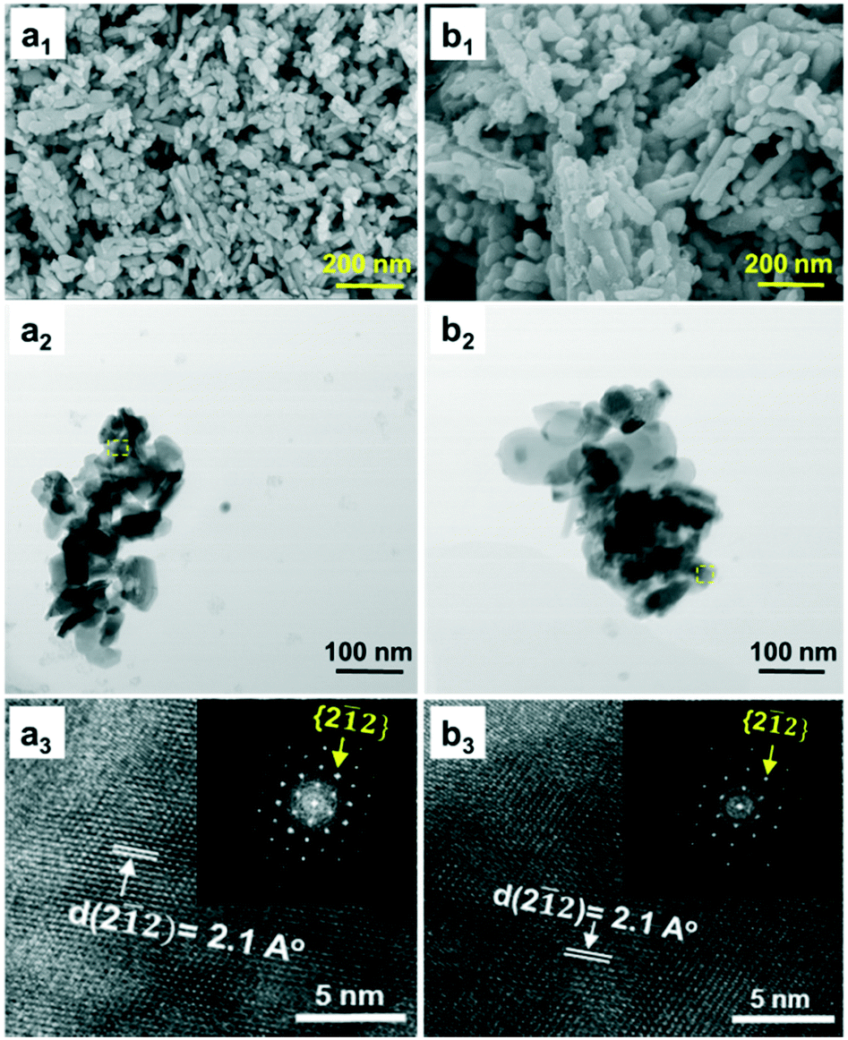 | ||
| Fig. 7 FESEM (a1 and b1), BF-STEM, (a2 and b2), and HRTEM images (a3 and b3) of fresh (a1–a3) and spent (b1–b3) CoMo2 catalysts. Reaction parameters: 200 W, CH4:CO2 = 1, VHSV = 10 L g−1 h−1. | ||
Meanwhile, the FESEM-EDX images of the Co/Al2O3 sample (Fig. S7†) show good dispersion of Co atoms onto the support surface, which coincides with the absence of its diffraction peaks from the XRD analysis. Conversely, the MoO2 particles are clearly observed from the FESEM-EDX images of the Mo/Al2O3 catalyst (Fig. S8†). Further, it is evident that the BF-STEM image of the fresh CoMo2 catalyst (Fig. 7a2) exhibiting elongated and prismatic aggregated particles is confirmed at the nanometric scale. The HRTEM together with the corresponding fast Fourier transform (FFT) analysis for a selected area (dashed yellow squares) indicates that the bimetallic catalyst system is extensively crystalline proven by the well-arranged dots (inset, Fig. 7a3). The HRTEM analysis result also reflects the interplanar distance (dspacing) of 2.1 Å of the lattice plane {2![[1 with combining macron]](https://www.rsc.org/images/entities/char_0031_0304.gif) 2} along the [110] zone axis. Unfortunately, the hexagonal atomic structure of Co0.82Mo0.18 bimetallic alloy could not be probed since it was effectively superimposed with other metallic species in the support leading to thicker areas, which is not appropriate for fringe lattice analyses. Alternatively, the STEM-EDX analysis can confirm the presence of this alloy. In good agreement with the abovementioned FESEM-EDX results of the fresh CoMo2 catalyst, the STEM-HAADF image (Fig. 8a), which exhibits the brightest locations containing higher atomic numbers of Co and Mo, together with the STEM-EDX results further (Fig. 8c) consolidate the presence of the bimetallic alloy on the support surface.
2} along the [110] zone axis. Unfortunately, the hexagonal atomic structure of Co0.82Mo0.18 bimetallic alloy could not be probed since it was effectively superimposed with other metallic species in the support leading to thicker areas, which is not appropriate for fringe lattice analyses. Alternatively, the STEM-EDX analysis can confirm the presence of this alloy. In good agreement with the abovementioned FESEM-EDX results of the fresh CoMo2 catalyst, the STEM-HAADF image (Fig. 8a), which exhibits the brightest locations containing higher atomic numbers of Co and Mo, together with the STEM-EDX results further (Fig. 8c) consolidate the presence of the bimetallic alloy on the support surface.
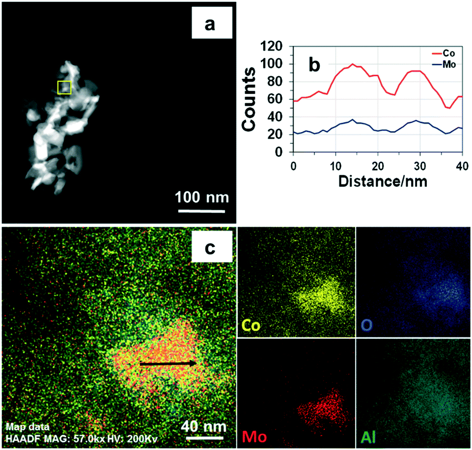 | ||
| Fig. 8 STEM-HAADF (a), line-scanning signals (b), and STEM-EDX (c) images of fresh CoMo2 catalyst. | ||
Moreover, as shown from the line-scanning analysis (Fig. 8b), the Co and Mo signals are visibly detected. The line-scanning analysis is in good accordance with the nanoscale mapping results (Fig. 8c). This reveals that the Co and Mo components are overlaid on each other, revealing the presence of the Co0.82Mo0.18 bimetallic alloy. In the meantime, the STEM-EDX qualitative spectrum of fresh CoMo2 catalyst (Fig. S10†) confirms all the constitutive elements, i.e., Co, Mo, O, and Al. The unlabeled peaks belong to the Cu grid. For the spent CoMo2 catalyst, insignificant sintering of particles was observed from the catalyst surface (Fig. 7b1), revealing the physical stability of the bimetallic catalyst. Likewise, all the STEM analysis results of the spent CoMo2 catalyst (Fig. 7b2 and b3 and S11†) confirm the stability of the crystal structure of the bimetallic catalyst that was maintained after 16 h on stream test under MW irradiation at MW power of 500 W. All these observed results, therefore, validate the stability of the bimetallic catalyst structure under MW irradiation. However, the previous long-time tests indicate a reduction in the catalytic activity at high MW power levels (e.g., 500 and 1000 W). Hence, the FESEM analyses at different magnifications for the spent CoMo2 catalyst samples tested under different MW power levels (200, 500, and 1000 W) were performed, and the results (Fig. S9†) exhibit visible sloughing and distortion on the CoMo2 surface after 16 h on stream of the DRM reaction under MW irradiation at 500 W. These deteriorations are particularly serious at higher MW power levels (e.g., 1000 W). On the other hand, at low MW power (e.g., 200 W) in which the CoMo2 catalyst can yield relatively higher reactant gas conversions (80% CH4 and 93% CO2), no visibly distinguishable differences are observed in the morphology between the fresh and spent catalyst samples. Hence, the outer physical deterioration would be the principal reason for the abovementioned decrease in the catalytic activity at higher MW power levels, as shown in Fig. 3. It is noteworthy that no sign of coke deposition could be observed from the spent CoMo2 catalyst (Fig. S10†). It is possible that the carbonaceous-free observation from the spent bimetallic catalyst is due to the mentioned Boudouard reaction promoted by MW irradiation to form more CO. The STEM-EDX qualitative spectrum also indicates the absence of C-related peaks from the spent CoMo2 catalyst (Fig. S12†). Positively, the catalytic DRM reaction driven by MW irradiation can assist in reducing the deposited coke and delivering higher catalytic activity.
3.3. Mechanism of catalytic activation for DRM under MW irradiation
Despite the fact that some research works have reported about catalytic DRM processes under MW heating, the activation mechanism of metallic-based catalysts by MW irradiation has not been fully understood. This is due to the fact that almost all the reported works either utilize C as the catalyst or mix metallic-based catalysts with a good MW absorber, i.e., C for DRM reaction under MW heating. This study explored that the Co–Mo/Al2O3 catalyst can directly absorb MW radiation and exhibit high catalytic activity for DRM, while their monometallic counterparts are inactive. The XRD results indicate the presence of Co0.82Mo0.18 alloy in bimetallic catalysts, which are distinguishable from monometallic catalyst samples. Therefore, from this observation, we can understand that the Co0.82Mo0.18 alloy is the MW acceptor component, which absorbs MW energy leading to heating the catalyst and catalyzing the DRM reaction. Indeed, it is generally recognized that magnetodielectric materials that simultaneously possess ferromagnetic and dielectric properties are the best MW absorbers.55–58 Co, known as a ferromagnetic element,59 can combine with other paramagnetic metals such as Mo (ref. 60) to form magnetodielectric materials for MW-absorbing applications.61 In this study, the magnetic properties as a function of the magnetic field of the prepared catalysts were measured by using SQUID. The results are shown in Fig. 9. The previous XRD patterns of the Co/Al2O3 catalyst indicate the absence of a Co-based diffraction pattern, which can be explained by the effective dispersion of Co-based particles in the support structure (Fig. S6†). However, it can be observed that the saturated magnetization is in the order of Co/Al2O3 > CoMo2 > Mo/Al2O3. The Co/Al2O3 catalyst exhibits a small M–H (magnetic moment–magnetic field) loop (Fig. 9), which is a representative feature for these soft ferromagnetic materials to absorb MW radiation. Consequently, the presence of well-dispersed metallic particles into the support can also effectively absorb the incident MW radiation.62,63 However, in this work, the Co/Al2O3 catalyst could not absorb MW energy presumably because of its high electrical conductivity, which causes the large reflection of the incident MW radiation.64 | ||
| Fig. 9 Hysteresis loops of the curves of fresh Mo/Al2O3, Co/Al2O3, and CoMo2 catalysts. | ||
The Mo/Al2O3 catalyst exhibited low magnetic characteristics (Fig. 9), limiting the ability to couple with the incident MW radiation.65 Hence, Mo/Al2O3 could not absorb MW energy. In the mixture of Co and Mo, conversely, the resultant Co–Mo/Al2O3 catalyst possesses higher saturated magnetization as compared to Mo/Al2O3 (Fig. 9).
Although it possesses lower saturated magnetization than Co/Al2O3, CoMo2 still exhibits the characteristics of a soft ferromagnetic material (small M–H loop), which is able to couple with the incident MW radiation.58,66 Therefore, Co–Mo/Al2O3 bimetallic catalysts in the presence of Co0.82Mo0.18 possessing magnetodielectric properties promote MW energy acceptance, which leads to its heating up to catalyze the DRM reaction. Under this situation, the Co0.82Mo0.18 alloy itself has a dual function in which it can serve as a MW-absorbing component and an active center for the DRM reaction. This mechanism is in good agreement with the other researchers65,67 who have also indicated that the best MW absorbers contain one of the phases responsible for coupling with electromagnetic waves, while the other works as an insulator to localize MW energy conversion.
As per the literature, both Co/Al2O3 and Mo/Al2O3 exhibit its catalytic activity for DRM under conventional heating. In these works, Co-based28 and Mo-based particles30 act as active centers for DRM reactions. Meanwhile, it is hypothesized that MW heating can generate internal heat sources for heterogeneous catalysts, which have inherent MW-absorbing capability.13 In this situation, the heated Co0.82Mo0.18 alloy can be considered as an internal heat source to simultaneously heat up adjacent metals, i.e., well-dispersed Co0, or metallic oxides, i.e., Co3O4 and MoO2, due to its effective dispersion with other components in the support, as shown in the FESEM-EDX and STEM-EDX results. The formation of these extra active centers results in the tremendous increase in the reactant conversions when reaching an initially active MW power level before exhibiting a gradually and slowly increasing rate with a subsequent increase in the MW power levels (Fig. 1). In particular, Co-based particles are well known as effective active centers for DRM reactions.68 By introducing additional auxiliary active centers under MW heating, the catalytic activity and stability of Co/Mo-supported Al2O3 catalysts was effectively preserved over 16 h TOS of DRM at low MW powers (Fig. 3), regardless of the observed reduction in the porosity as indicated by the previous BET analyses. Nonetheless, an excessive Co molar loading (e.g., Co/Mo ratio of 2.5) possibly either leads to an increase in the electrical conductivity (generated by the additional reduced Co particles) or promotes the formation of the abovementioned inactive phases such as Co2Mo3O8 (Fig. S5†), smothering the active centers from the incident MW radiation. These two consequences engender the reduction in the MW-absorbing capability, and therefore, diminish the catalytic activity.
Conclusions
In this work, the catalytic activity of a series of Co- and Mo-based catalysts supported by Al2O3 for DRM under MW irradiation at the ambient pressure were explored. As compared to the reported previous works focusing on C-containing catalysts, the Co–Mo/Al2O3 catalyst with Co/Mo molar ratio of 2 delivered higher activity and stability for DRM converting CH4 (80%) and CO2 (93%) to the syngas with H2/CO ratio of 0.80 under lower MW irradiation power of 200 W. Our results highlight the high activity of the bimetallic catalyst attributed to the MW-absorbing ability of the Co0.82Mo0.18 alloy combining the ferromagnetic and dielectric properties. The developed bimetallic catalyst exhibited an intrinsic ability to absorb MW energy without the involvement of extra MW acceptors such as C-based materials, leading to better catalytic stability. There is no significant sign for catalyst decay during the 16 h stability test at low MW power levels (<500 W). The MW-heated DRM process over Co–Mo/Al2O3 catalyst in this study is flexible and relocatable, and therefore, appropriate for FPSOV systems to efficiently use these remote and stranded gas reserves via the Fischer–Tropsch synthesis.Conflicts of interest
There are no conflicts to declare.Acknowledgements
The authors acknowledge the financial support from Australian Research Council (ARC) Linkage project - LP150101158, and EcoTechnol Pty. Co, Perth, Australia. The help from Ning Han for XRD analysis is highly appreciated.Notes and references
- W. Hoppe, S. Bringezu and N. Thonemann, J. Cleaner Prod., 2016, 121, 231–237 CrossRef.
- J.-M. Lavoie, Front. Chem., 2014, 2, 81 Search PubMed.
- H. Meng, L. Kloul and A. Rauzy, Appl. Ocean Res., 2018, 74, 117–126 CrossRef.
- M. Ao, G. H. Pham, V. Sage and V. Pareek, J. Mol. Catal. A: Chem., 2016, 416, 96–104 CrossRef.
- A. Löfberg, J. Guerrero-Caballero, T. Kane, A. Rubbens and L. Jalowiecki-Duhamel, Appl. Catal., B, 2017, 212, 159–174 CrossRef.
- M. Usman, W. M. A. Wan Daud and H. F. Abbas, Renewable Sustainable Energy Rev., 2015, 45, 710–744 CrossRef.
- J. Menéndez, A. Arenillas, B. Fidalgo, Y. Fernández, L. Zubizarreta, E. Calvo and J. Bermúdez, Fuel Process. Technol., 2010, 91, 1–8 CrossRef.
- D. Varisli, C. Korkusuz and T. Dogu, Appl. Catal., B, 2017, 201, 370–380 CrossRef.
- J.-Q. Zhang, Y.-J. Yang, J.-S. Zhang and Q. Liu, Acta Chim. Sin., 2002, 60, 1973–1980 Search PubMed.
- T.-S. Kim, S. Song, K.-M. Chun and S. H. Lee, Energy, 2010, 35, 2734–2743 CrossRef.
- M. Jasiński, M. Dors and J. Mizeraczyk, J. Power Sources, 2008, 181, 41–45 CrossRef.
- X. Tao, M. Bai, X. Li, H. Long, S. Shang, Y. Yin and X. Dai, Prog. Energy Combust. Sci., 2011, 37, 113–124 CrossRef.
- A. Dastan, A. Kulkarni and B. Torok, Green Chem., 2012, 14, 17–37 RSC.
- B. Fidalgo and J. A. Menéndez, Fuel Process. Technol., 2012, 95, 55–61 CrossRef.
- B. Fidalgo, A. Domínguez, J. J. Pis and J. A. Menéndez, Int. J. Hydrogen Energy, 2008, 33, 4337–4344 CrossRef.
- A. Domínguez, Y. Fernández, B. Fidalgo, J. J. Pis and J. A. Menéndez, Energy Fuels, 2007, 21, 2066–2071 CrossRef.
- B. Fidalgo, A. Arenillas and J. A. Menéndez, Fuel, 2010, 89, 4002–4007 CrossRef.
- L. Li, Z. Yang, J. Chen, X. Qin, X. Jiang, F. Wang, Z. Song and C. Ma, Fuel, 2018, 215, 655–664 CrossRef.
- L. Li, H. Wang, X. Jiang, Z. Song, X. Zhao and C. Ma, Fuel, 2016, 185, 692–700 CrossRef.
- J. A. Menéndez, A. Arenillas, B. Fidalgo, Y. Fernández, L. Zubizarreta, E. G. Calvo and J. M. Bermúdez, Fuel Process. Technol., 2010, 91, 1–8 CrossRef.
- V. R. R. Pendyala, W. D. Shafer, G. Jacobs, M. Martinelli, D. E. Sparks and B. H. Davis, RSC Adv., 2017, 7, 7793–7800 RSC.
- B. V. Ayodele, S. S. Hossain, S. S. Lam, O. U. Osazuwa, M. R. Khan and C. K. Cheng, J. Nat. Gas Sci. Eng., 2016, 34, 873–885 CrossRef.
- B. V. Ayodele, M. R. Khan, S. S. Lam and C. K. Cheng, Int. J. Hydrogen Energy, 2016, 41, 4603–4615 CrossRef.
- N. A. Abd Ghani, A. Azapour, A. F. a. Syed Muhammad and B. Abdullah, Int. J. Hydrogen Energy, 2018, 1–8 Search PubMed , in press.
- B. V. Ayodele, M. R. Khan and C. K. Cheng, Int. J. Hydrogen Energy, 2016, 41, 198–207 CrossRef.
- O. Marin-Flores, T. Turba, C. Ellefson, K. Wang, J. Breit, J. Ahn, M. G. Norton and S. Ha, Appl. Catal., B, 2010, 98, 186–192 CrossRef.
- A. E. Awadallah, A. A. Aboul-Enein and A. K. Aboul-Gheit, Energy Convers. Manage., 2014, 77, 143–151 CrossRef.
- J. L. Ewbank, L. Kovarik, C. C. Kenvin and C. Sievers, Green Chem., 2014, 16, 885–896 RSC.
- É. Horváth, K. Baán, E. Varga, A. Oszkó, Á. Vágó, M. Törő and A. Erdőhelyi, Catal. Today, 2017, 281, 233–240 CrossRef.
- M. Gaillard, M. Virginie and A. Y. Khodakov, Catal. Today, 2017, 289, 143–150 CrossRef.
- M. Li, H. Li, F. Jiang, Y. Chu and H. Nie, Catal. Today, 2010, 149, 35–39 CrossRef.
- S. A. Ali, S. Ahmed, K. W. Ahmed and M. A. Al-Saleh, Fuel Process. Technol., 2012, 98, 39–44 CrossRef.
- W. Chen, X. Long, M. Li, H. Nie and D. Li, Catal. Today, 2017, 292, 97–109 CrossRef.
- H. K. Kim, C.-W. Lee, M. Kim, J. H. Oh, S. A. Song, S.-C. Jang, C. W. Yoon, J. Han, S. P. Yoon, S. W. Nam, D.-K. Choi, Y.-g. Shul and H. C. Ham, Int. J. Hydrogen Energy, 2016, 41, 18846–18857 CrossRef.
- P. A. Nikulshin, A. V. Mozhaev, A. A. Pimerzin, V. V. Konovalov and A. A. Pimerzin, Fuel, 2012, 100, 24–33 CrossRef.
- N. M. Maximov, N. N. Tomina, P. S. Solmanov and A. A. Pimerzin, Russ. J. Appl. Chem., 2017, 90, 574–581 CrossRef.
- S. J. Ardakani, M. Alyani and K. J. Smith, Can. J. Chem. Eng., 2016, 94, 655–661 CrossRef.
- C. Egawa, J. Catal., 2018, 358, 35–42 CrossRef.
- D. Liu, X. Y. Quek, W. N. E. Cheo, R. Lau, A. Borgna and Y. Yang, J. Catal., 2009, 266, 380–390 CrossRef.
- N. Abdel Karim Aramouni, J. Zeaiter, W. Kwapinski and M. N. Ahmad, Energy Convers. Manage., 2017, 150, 614–622 CrossRef.
- J. Hunt, A. Ferrari, A. Lita, M. Crosswhite, B. Ashley and A. E. Stiegman, J. Phys. Chem. C, 2013, 117, 26871–26880 CrossRef.
- B. Fidalgo, A. Arenillas and J. A. Menéndez, Fuel Process. Technol., 2011, 92, 1531–1536 CrossRef.
- L. Li, X. Jiang, H. Wang, J. Wang, Z. Song, X. Zhao and C. Ma, J. Anal. Appl. Pyrolysis, 2017, 125, 318–327 CrossRef.
- L. M. Kustov, A. L. Tarasov, O. P. Tkachenko and G. I. Kapustin, Ind. Eng. Chem. Res., 2017, 56, 13034–13039 CrossRef.
- L. S. Gangurde, G. S. J. Sturm, T. J. Devadiga, A. I. Stankiewicz and G. D. Stefanidis, Ind. Eng. Chem. Res., 2017, 56, 13379–13391 CrossRef PubMed.
- X. Zhang, C. S.-M. Lee, D. M. P. Mingos and D. O. Hayward, Catal. Lett., 2003, 88, 129–139 CrossRef.
- I. V. Zagaynov, A. S. Loktev, A. L. Arashanova, V. K. Ivanov, A. G. Dedov and I. I. Moiseev, Chem. Eng. J., 2016, 290, 193–200 CrossRef.
- T. Odedairo, J. Ma, J. Chen, S. Wang and Z. Zhu, J. Solid State Chem., 2016, 233, 166–177 CrossRef.
- L. S. Gangurde, G. S. J. Sturm, M. J. Valero-Romero, R. Mallada, J. Santamaria, A. I. Stankiewicz and G. D. Stefanidis, Chem. Eng. Process., 2018, 127, 178–190 CrossRef.
- W. Li, J. Liu and D. Zhao, Nat. Rev. Mater., 2016, 1, 16023 CrossRef.
- Z. Ferencz, A. Erdőhelyi, K. Baán, A. Oszkó, L. Óvári, Z. Kónya, C. Papp, H. P. Steinrück and J. Kiss, ACS Catal., 2014, 4, 1205–1218 CrossRef.
- J. Ji, X. Duan, G. Qian, X. Zhou, G. Tong and W. Yuan, Int. J. Hydrogen Energy, 2014, 39, 12490–12498 CrossRef.
- B. Wang, Y. Yang, L.-J. Li and Y. Chen, J. Mater. Sci., 2009, 44, 3285–3295 CrossRef.
- S. M. Gaytan, L. E. Murr, E. Martinez, J. L. Martinez, B. I. Machado, D. A. Ramirez, F. Medina, S. Collins and R. B. Wicker, Metall. Mater. Trans. A, 2010, 41, 3216–3227 CrossRef.
- Y. Khani, Z. Shariatinia and F. Bahadoran, Chem. Eng. J., 2016, 299, 353–366 CrossRef.
- S. Das, G. C. Nayak, S. K. Sahu, P. C. Routray, A. K. Roy and H. Baskey, J. Magn. Magn. Mater., 2015, 377, 111–116 CrossRef.
- X. Li, J. Feng, Y. Du, J. Bai, H. Fan, H. Zhang, Y. Peng and F. Li, J. Mater. Chem. A, 2015, 3, 5535–5546 RSC.
- A. Maqsood and K. Khan, J. Alloys Compd., 2011, 509, 3393–3397 CrossRef.
- N. Tsyntsaru, H. Cesiulis, E. Pellicer, J.-P. Celis and J. Sort, Electrochim. Acta, 2013, 104, 94–103 CrossRef.
- C. D. Brondino, M. G. Rivas, M. J. Romão, J. J. Moura and I. Moura, Acc. Chem. Res., 2006, 39, 788–796 CrossRef PubMed.
- V. Petrov and V. Gagulin, Inorg. Mater., 2001, 37, 93–98 CrossRef.
- N. Clark, N. Jones and A. Porch, Sens. Actuators, A, 2017, 259, 137–143 CrossRef.
- C. Wang, R. Lv, Z. Huang, F. Kang and J. Gu, J. Alloys Compd., 2011, 509, 494–498 CrossRef.
- R. R. Mishra and A. K. Sharma, Composites, Part A, 2016, 81, 78–97 CrossRef.
- S. Horikoshi and N. Serpone, Catal. Sci. Technol., 2014, 4, 1197–1210 RSC.
- L. M. Kustov and I. M. Sinev, Russ. J. Phys. Chem. A, 2010, 84, 1676–1694 CrossRef.
- D. E. Clark, D. C. Folz and J. K. West, Mater. Sci. Eng., A, 2000, 287, 153–158 CrossRef.
- H. Ay and D. Üner, Appl. Catal., B, 2015, 179, 128–138 CrossRef.
Footnote |
| † Electronic supplementary information (ESI) available. See DOI: 10.1039/c8cy01601a |
| This journal is © The Royal Society of Chemistry 2018 |