
 Open Access Article
 This Open Access Article is licensed under a
 Creative Commons Attribution 3.0 Unported Licence
Carbon-based SILP catalysis for the selective hydrogenation of aldehydes using a well-defined Fe(II) PNP complex
Rafael
Castro-Amoedo†
a,
Zita
Csendes†
a,
Julian
Brünig
a,
Markus
Sauer
 b,
Annette
Foelske-Schmitz
b,
Nevzat
Yigit
c,
Günther
Rupprechter
c,
Tushar
Gupta
c,
Ana Margarida
Martins
d,
Katharina
Bica
a,
Helmuth
Hoffmann
*a and
Karl
Kirchner
*a
b,
Annette
Foelske-Schmitz
b,
Nevzat
Yigit
c,
Günther
Rupprechter
c,
Tushar
Gupta
c,
Ana Margarida
Martins
d,
Katharina
Bica
a,
Helmuth
Hoffmann
*a and
Karl
Kirchner
*a
aInstitute of Applied Synthetic Chemistry, Vienna University of Technology, Getreidemarkt 9, A-1060 Vienna, Austria. E-mail: helmuth.hoffmann@tuwien.ac.at; karl.kirchner@tuwien.ac.at
bAnalytical Instrumentation Center, Vienna University of Technology, Getreidemarkt 9, A-1060 Vienna, Austria
cInstitute of Materials Chemistry, Vienna University of Technology, Getreidemarkt 9, A-1060 Vienna, Austria
dCentro de Química Estrutural, Instituto Superior Técnico, Universidade de Lisboa, Av. Rovisco Pais No. 1, 1049-001 Lisboa, Portugal
First published on 27th August 2018
Abstract
In this work, the supported ionic liquid phase (SILP) method was applied for the immobilization of a newly developed, well-defined hydride Fe(II) PNP pincer complex dissolved in ionic liquid (IL) onto polymer-based spherical activated carbon. This novel SILP catalyst was structurally characterized by electron microscopy, N2 adsorption–desorption, FTIR, and XPS measurements and was used for the hydrogenation of aldehydes to alcohols. For an optimized pore filling degree, this system showed excellent activity in the chemoselective hydrogenation of different aldehydes and proved to be reusable in at least seven consecutive reaction cycles without any loss in activity. Significantly lower reaction rates were observed, however, compared to a recent study of the same catalyst supported on silica, which was ascribed to the different pore sizes of these two support materials.
Introduction
The catalytic reduction of carbonyl groups using molecular hydrogen represents a way to obtain valuable alcohols, used for the production of bulk and fine chemicals in a green and economical way.1 This reaction is typically catalyzed by both precious metal2 and earth-abundant non-precious metal catalysts.3,4 Our group recently reported the application of [Fe(PNPMe-iPr)(CO)(H)(Br)] (1) and trans-[Fe(PNPMe-iPr)(H)2(CO)] (2) as (pre-)catalysts for the homogeneous, chemoselective hydrogenation of aldehydes.5 The dihydride complex 2 is rapidly formed from 1 in the presence of H2 and DBU (1,8-diaza-bicyclo[5.4.0]undec-7-ene) as base and is the actual catalyst. These complexes were found to be among the most efficient catalysts published to date. Nevertheless, the major drawback of homogeneous catalysts is the need for their separation at the end of the catalytic process. This shortcoming can be eliminated by immobilizing transition metal complexes onto different supports.6 However, the activity of a sensitive homogeneous catalyst is often decreased or lost upon its direct immobilization, since the active compound suffers a modification of its chemical and physical properties.Ionic liquids (ILs) have attracted much attention as alternative efficient and benign reaction media for the immobilization of homogeneous catalysts for various catalytic reactions, either in liquid–liquid biphasic processes or for the design of supported liquid catalysts.7 In the supported ionic liquid phase (SILP) technology, the homogeneous catalyst is dissolved in the ionic liquid and deposited on a mesoporous solid material; thus, its chemical nature can be preserved, while the applied solvent is not miscible with the IL and is enriched with the product of the catalyzed reaction. SILP catalysis allows for a straightforward separation of the product from the transition metal complex; moreover, the high surface area provided by the mesoporous support material results in high reactivity. In general, it may be considered as green and sustainable technology, since it combines the main advantages of heterogeneous and homogeneous catalysis, providing a homogeneous environment for the reaction that is particularly well suited for gas phase continuous flow processes with fixed-bed reactor set-up.8
A number of different support materials can, and have been, used for the preparation of SILP catalysts, including silica, carbon, alumina or titanium based porous materials as well as their combinations. While amorphous silica-based materials are by far the most popular choice, the acidic surface composition might interfere with the catalytic reaction or with the catalyst itself, particularly when sensitive species such as well-defined base metal catalysts are involved. Activated carbon materials are promising supports for SILP catalysis because of their high surface area, stability, inertness, and adsorption capacity.9 These can be easily customized for the particular reaction since their surface area, pore volume and surface chemistry are tunable. The leaching of both IL and catalyst can be negligible by applying carbon supports with high volumes of supermicro and mesopores.10 Most recently, Weiß et al. showed that undesired side reaction in the gas phase hydroformylation of ethylene could be avoided by replacing silica-based SILP catalysts with nitrogen-doped carbon materials and emphasized the importance of support chemistry for long-term stability in industrially viable processes.11
In this work, we present the preparation, characterization, and application of complex 1 immobilized in an activated carbon SILP system. To the best of our knowledge, this is the first example of a well-defined Fe(II) complex applied as a carbon-based SILP system for the selective hydrogenation of aldehydes to afford alcohols.
Experimental
Materials
All manipulations were performed under argon atmosphere using Schlenk techniques or/and in a MBraun inert-gas glovebox. All solvents were purified according to standard procedures.12 The deuterated solvents were purchased from Aldrich and dried over 4 Å molecular sieves. The IL, 1-ethyl-2,3-dimethylimidazolium bis(trifluoromethylsulfonyl)imide ([C2m2im][NTf2]), 99% purity, was purchased from IoLiTec and was dried for at least 24 h at room temperature and ∼10−2 mbar before use and was stored under an argon atmosphere. Polymer-based spherical activated carbon (CARB) was used as support (donated by Blücher GmbH) and was degassed under vacuum at 300 °C for 6 h. The complex [Fe(PNPMe-iPr)(CO)(H)(Br)] (1) was prepared according to the literature.5 All aldehyde substrates were obtained from commercial sources and purified by distillation prior to use. Hydrogen (99.999% purity) was purchased from Messer Austria and used as received.Catalyst preparation
In order to find the optimum impregnation of the support, 5 mg complex 1 and 30–60 μl IL in 2 ml ethanol were added to 100 mg CARB and stirred for 5 minutes, under inert atmosphere. Then, the solvent was evaporated under vacuum (∼10−2 mbar) at 60 °C until the spheres presented rolling behavior again (∼10 min).Material characterization
Scanning electron microscopy (SEM) images were acquired using FEI Quanta 250 FEGSEM scanning electron microscope at 5 kV. Transmission electron microscopy (TEM) images were obtained using FEI TECNAI F20 transmission electron microscope at 200 kV. The sample was mildly grinded to preserve the porous structure and stirred in ethanol for 6 hours then sonicated for 30 minutes to ensure an optimal dispersion. Two drops from the well dispersed top part were taken and dropped in a copper Lacey carbon-coated grid. X-ray photoelectron spectroscopy (XPS) measurements were carried out on a SPECS XPS-spectrometer equipped with a monochromatized Al-Kα Xray source (μFocus 350) and a hemispherical WAL-150 analyzer (acceptance angle: 60°). Samples were mounted onto the sample holder using double-sided Cu tape or Ta. Pass energies of 100 eV and 30 eV and energy resolutions of 1 eV and 100 meV were used for survey and detail spectra respectively (excitation energy: 1486.6 eV, beam energy and spot size: 70 W onto 400 μm, angle: 51° to sample surface normal, base pressure: 6 × 10⁻¹⁰ mbar, pressure during measurements: 2 × 10⁻⁹ mbar). Data analysis was performed using CASA XPS software packages employing Shirley backgrounds13 and Scofield sensitivity factors.14 Charge correction was applied, so the adventitious carbon peak (C–C peak) was shifted to 284.8 binding energy (BE). Curve fits using combined Gaussian–Lorentzian peak shapes were used to discern the components of detail spectra. To reduce charging effects a broad spot low energy electron source (SPECS FG 22 flood gun) was used for charge compensation (5 eV/25 μA). The detection limit in survey measurements lies around 0.1–0.5 at%, depending on the element. The accuracy of XPS measurements is around 10–20% of the values shown, and the maximum depth is about 7–10 nm.1H, 19F{1H}, and 31P{1H} NMR spectra were recorded on Bruker AVANCE-250 spectrometer. 1H spectra were referenced internally to residual protic-solvent resonances and are reported relative to tetramethylsilane (δ = 0 ppm). 31P{1H} NMR spectra were referenced externally to H3PO4 (85%) (δ = 0). 19F{1H} spectra were referenced externally to trifluorotoluene (0.05%) (δ = 0 ppm).
FTIR spectra were recorded in diffuse reflectance with a Bruker Vertex 80 FTIR spectrometer using a narrow band MCT detector and a Harrick Seagull reflection optical unit. The scanned wavenumber range was 4000 cm−1 to 800 cm−1. 256 scans were collected for each spectrum with 4 cm−1 resolution. The spectra were baseline corrected. N2 adsorption–desorption isotherms were measured at 77 K with a volumetric adsorption analyzer (Micromeritics, ASAP 2020) using the Brunauer–Emmett–Teller (BET) theory for determining the surface area and the non-local density functional theory (NLDFT) method for calculating the pore size distribution and pore volumes. Fe leaching was monitored using an inductively coupled plasma (ICP) optical emission spectrometer PerkinElmer OPTIMA 8300 equipped with an SC-2 DX FAST sample preparation system. A customized single-element (Merck, Roth) standard was used for the calibration. All samples were extracted using ethanol and methanol (two times each), followed by solvent-evaporation and acid-digestion (HNO3 and H2O2 at a 2![[thin space (1/6-em)]](https://www.rsc.org/images/entities/char_2009.gif) :1 ratio).
:1 ratio).
General procedure for the hydrogenation of aldehydes
All hydrogenation reactions were performed in a Carl Roth 100 ml autoclave at room temperature (25 °C), under hydrogen pressures between 10 to 40 bar. For preparing the reaction mixture, a vial was charged with the impregnated support or catalyst dissolved in IL and was placed in the autoclave. Then, the autoclave was evacuated and flushed with argon three times. Subsequently, 5 mol% DBU, 2 ml heptane and 2 mmol aldehyde were taken up into a syringe and injected into the autoclave. After flushing it three times with hydrogen, the desired hydrogen pressure was established, and the reaction was carried out for the stated time. Afterward, the hydrogen gas was released, and the sample was analyzed by 1H and/or 19F{1H} NMR spectroscopy to determine the conversions by integrating the aldehyde and alcohol signals.Results and discussion
Characterization of the support
Fig. 1 shows electron microscopy images of the untreated CARB support employed in this study. It consists of evenly-sized carbon spheres with diameters of about 400 μm. In the TEM image (Fig. 1B), the microcrystalline nature is clearly evident from the superimposed grid pattern corresponding to the graphitic carbon layers. On top of that, a larger-sized pattern of parallel light and dark stripes with a distance of about 1 nm can be seen, in particular at the outer edges of the particle in Fig. 1B, which indicates the presence of micropores. However, it must be emphasized here that the native porous structure of the carbon spheres is probably at least partly destroyed in the process of TEM sample preparation.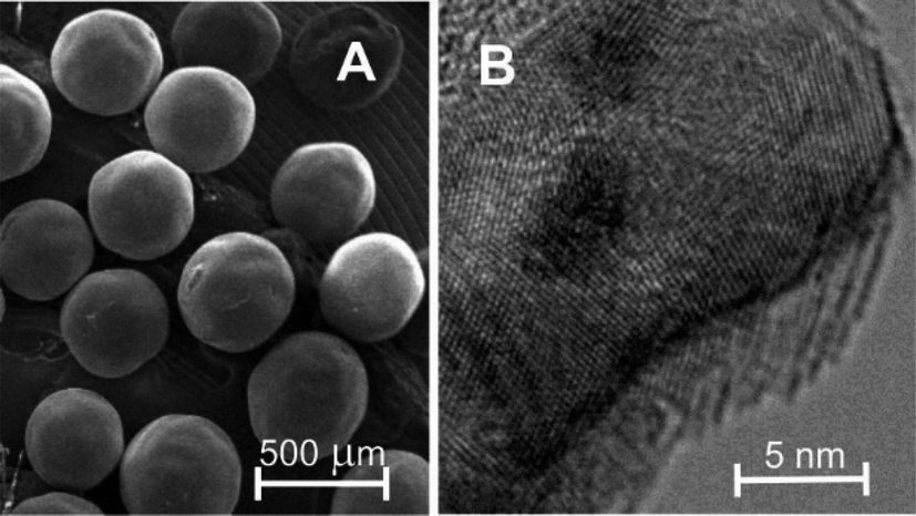 | ||
| Fig. 1 SEM image (A) and TEM image (B) of CARB, a polymer-based spherical activated carbon. | ||
An important task in this work was to determine the surface composition of CARB, since, depending on their nature, surface groups can interact with the catalyst, IL, substrate, and product. Complex 1 is very sensitive to highly coordinating and/or acidic groups such as carboxyl and phenol groups. XPS measurements were used to determine the atomic composition of the surface and to quantify the carbon bonds on the surface. It was found that the surface (to a depth of 7–10 nm) of CARB contains 94 at% C, 5 at% O, and <1 at% other elements. Analysis of the C 1s detail spectrum of CARB (Fig. 2) revealed that the carbon signal mostly consists of three major components corresponding to three different bonding environments: C–C at 284.7 eV (78 at%), C–O at 286.4 eV (7 at%), and C![[double bond, length as m-dash]](https://www.rsc.org/images/entities/char_e001.gif) O at 287.7 eV (4 at%).15 In addition, we could evidence a shakeup peak around 290.4 eV (11.5 at%).
O at 287.7 eV (4 at%).15 In addition, we could evidence a shakeup peak around 290.4 eV (11.5 at%).
 | ||
| Fig. 2 C 1s spectrum of CARB. | ||
The lack of an O–CO peak at ∼289 eV suggests that the surface does not contain strongly acidic functionalities such as carboxylic, anhydride, lactone and lactol groups, which in turn are extremely dangerous to our catalyst. This absence is in good agreement with the 900 °C heat treatment used in the activation step of the carbon spheres since this high temperature can selectively remove these acidic groups from the activated carbon surface.16 However, some weakly acidic phenol groups may be present on the surface, since the carbon signal contains 7 at% C–O bonds which can be attributed to phenol and ether functionalities. The CO bonds are likely due to ketones and quinones. The pH value of CARB was found to be 8.4 which confirms the overall presence of more basic than acidic groups making the support suitable for our catalytic applications without further modification.17
The shape of the N2 adsorption–desorption isotherm of CARB (Fig. 3A) is of type I + IV according to the IUPAC classification, which is characteristic of materials with micro- and mesoporosity.18 Due to the presence of micropores, larger adsorption occurs at low adsorbate pressures, while at higher pressures capillary condensation takes place in the mesopores. The steep increase of the isotherm close to the saturation pressure represents the pore filling of large meso/small macropores with pore diameters of 50 nm and above. The BET surface area and the available micro/mesopore volumes of the material were calculated from the isotherm and are listed in Table 1.
 | ||
| Fig. 3 N2 adsorption–desorption isotherm of CARB (A) and CARB80 (B). | ||
| Sample | S BET (m2 g−1) | V total (cm3 g−1) | V nμp (cm3 g−1) | V sμp (cm3 g−1) | V meso (cm3 g−1) | α exp (%) |
|---|---|---|---|---|---|---|
| a BET surface area. b Total pore volume, N2 volume adsorbed at p/p0 = 0.98. c Narrow micropore (<0.7 nm) volume. d Supermicropore (0.7 < d < 2 nm) volume. e Mesopore (2 < d < 50 nm) volume. f Experimental pore filling degree = [Vtotal(CARB) − Vtotal(CARB80)]/Vtotal (CARB) × 100. | ||||||
| CARB | 1728 | 1.18 | 0.10 | 0.55 | 0.33 | 0 |
| CARB-80 | 218 | 0.28 | 0.01 | 0.06 | 0.13 | 76 |
We can conclude so far that CARB is a promising candidate for SILP catalysis. It lacks acidic surface groups and does not require functionalization under harsh conditions. Moreover, it has a large surface area and contains a high amount of micropores, which offers stability against IL leaching.10
Optimizing the impregnation of CARB
The second task was to find the optimum impregnation conditions regarding the amount of ionic liquid and the resulting pore filling degree of the carbon support. The hydrogenation of 4-fluorobenzaldehyde with complex 1 as pre-catalyst at 10 bar hydrogen pressure and 3 h reaction time was chosen to compare SILP catalysts with different IL loadings (Table 2). In light of the common sensitivity of aldehydes towards highly basic conditions, DBU (1,8-diaza-bicyclo[5.4.0]undec-7-ene) was found to be a suitable co-catalyst (base).5 In fact, it has to be noted that the hydrogenation of cinnamaldehyde did not proceed in the presence of tBuOK, revealing the benefits of employing DBU as base in all reactions as reported previously.5 As solvent n-heptane was used since neither the catalysts nor the IL were soluble in this solvent and leaching was not observed (vide infra), whereas both substrates and products were highly soluble in this solvent.
In entries 1–4, the amount of IL (VIL) was changed, keeping the amount of support and catalyst constant (mCARB = 100 mg, mCAT = 5 mg) in order to find the optimum IL loading. It is clearly seen that full conversion was achieved in 3 h when CARB was impregnated with 80 weight percent IL/cat 1 solution. We refer to this material as CARB80. At both lower and higher IL loadings, the conversion drops rapidly, similar to a recent study of our group using silica as support material.21 The sharp maximum of conversion as a function of IL loading observed here is believed to be directly related to the pore structure and pore size distribution of the carbon support and can be qualitatively understood as follows: at low IL loadings, the IL/catalyst solution is contained mostly in micropores, which are filled from bottom to top and have only a small interface area with the surrounding reactant solution and yield accordingly low reaction rates. Once the micropores are completely filled, the mesopores get filled by adsorption of the IL/catalyst solution at the inner pore walls. This is where the catalyst has its highest activity due to the comparatively large interface area with the reactant solution. At even larger IL loadings, also the meso- and macropores get completely filled and the catalyst activity drops again.
Characterization of CARB80
Structural parameters derived from the N2 adsorption–desorption isotherm (Fig. 3B, Table 1) showed that both the BET surface area and the total pore volume decreased after IL/catalyst impregnation due to the coating of the carbon surface and the clogging of micropores. The presence of blocked pores means that there are pores inside CARB80 which do not contain IL but are not accessible to N2. This behavior is likely for microporous materials with pore diameters smaller than the size of the IL molecules. It also explains the discrepancy between the experimental pore filling degree of 76% (Table 1) compared to the nominal value of 42% (Table 2) for CARB80.FTIR measurements (Fig. 4) clearly support a successful impregnation of the IL/catalyst inside the porous carbon substrate, since characteristic peaks of [C2m2im][NTf2] (Fig. 4A) can be seen in the spectrum of CARB80 (Fig. 4B). The strong peaks between 1400 and 1000 cm−1 are related to the vibrations of the [NTf2] anion.19 The peak at 1054 cm−1 is assigned to the asymmetric stretch of the SNS group, the vibration at 1190 cm−1 corresponds to the asymmetric CF3 stretch while the bands at 1350 and 1140 cm−1 belong to the asymmetrical and symmetrical SO2 stretching vibration, respectively. The peaks between 1600 and 1400 cm−1 are related to the cation [C2m2im] and include the highly characteristic CC/CN coupled stretching mode of the imidazolium ring at 1587 cm−1 and the CH2 scissors deformation δ(CH2) at 1470 cm−1.20 However, the peaks of complex 1 are essentially invisible in the spectrum of CARB80 due to its low concentration in the impregnated SILP material.
 | ||
| Fig. 4 FTIR spectra of A) [C2m2im][NTf2] and B) CARB80 (the spectrum of CARB was subtracted). | ||
XPS measurements were used to analyze the surface composition of CARB80. CARB80 shows decreased C content and increased O content compared to the unaltered CARB. The sample also exhibits 6.3 at% F, 2.7 at% N and 1.4 at% S, indicating that a significant amount of IL is present in the porous carbon. It was found that the N 1s detail spectrum of CARB80 contained two components at 399.0 eV and 401.4 eV corresponding to [NTf2] and [C2m2im], respectively (Fig. 5A). The F 1s detail spectrum (Fig. 5B) shows one component at 689.0 eV which is attributed to the [NTf2] anion. The catalyst complex 1 in the CARB80 sample, however, is below the detection limit of XPS.
 | ||
| Fig. 5 XP spectra of CARB80 A) N 1s and B) F 1s. | ||
Hydrogenations using CARB80 as catalyst
As previously described,5 the first step of the catalytic cycle is the activation of catalyst 1 to form the trans-dihydride complex 2 which is the catalytically active species. The performance of this catalyst in the carbon-based SILP matrix (CARB80) was tested in the room temperature hydrogenation of different aromatic aldehydes to the corresponding alcohols in n-heptane solution and was compared to the results of a previous study of the same catalyst in a silica-based SILP matrix.21 These results are presented in Table 3. Aldehyde A1 (4-fluorobenzaldehyde) was used to investigate the influence of the hydrogen pressure and the substrate/catalyst (S/C) ratio (entries 1–5). Doubling the pressure from 10 to 20 bar boosts up the conversion by a factor of 5, whereas a further pressure increase to 30 and 40 bar has a comparatively small effect. Increasing the S/C ratio from 200 to 1000 at 40 bar hydrogen pressure yields only a moderate increase in the TON and TOF values and a substantial drop of the reaction yield (entry 5). Quantitative conversion with 10 bar H2 pressure and S/C = 200 is reached for a reaction time of 3 h (entry 6). In a previous study,21 this reaction was carried out under comparable conditions with silica instead of carbon as the support material and an approximately 10-fold faster conversion was observed (entry 7). Finally, we have also compared the hydrogenation of some other aromatic aldehydes A2–A4 under identical reaction conditions for carbon and silica supports (entries 8–13). If present, CC double bonds remained unaffected, as in the case of the challenging α,β-unsaturated cinnamaldehyde (A4). Ketones, nitriles, esters and amides were not hydrogenated under these reaction conditions as already reported recently also with silica-based SILP catalysts.21 In all cases, quantitative conversion was obtained, yet, at significantly slower reaction rates with the catalyst immobilized in the carbon matrix CARB80. The main reason for this different performance of carbon- and silica-based SILP catalysts is believed to lie in the different pore sizes of these two support materials. The silica used in the SILP20 catalyst is a typical mesoporous material with pore diameters in the 5–15 nm range. With an estimated thickness of ∼0.6 nm for a monolayer of [C2m2im][NTf2],22 these pores can be coated with several layers of IL/catalyst solution and still remain open pores with high surface area and easy access for the reaction solution. The carbon support used in this work, on the other hand, contains a high percentage of micropores with diameters <2 nm, which are either inaccessible (d < 0.6 nm) or completely filled with [C2m2im][NTf2], as evidenced by the steep rise of the N2 adsorption isotherm at low pressures (Fig. 3A). The slower conversion compared to the silica support might therefore be caused primarily by the smaller interface area and the larger diffusion paths of the carbon-based SILP catalysts.
|
|
||||||||
|---|---|---|---|---|---|---|---|---|
| Entry | Aldehyde | Support | S/C | P (bar) | Time (min) | Conversionc (%) | TON | TOF (h−1) |
| a Conditions: entry 1–4, 6, 8, 10, 12: 2 mmol substrate, 180 mg of CARB80 (5 mg of 1, 75 mg of IL, 100 mg of CARB); entry 5: 10 mmol substrate, 180 mg of CARB80 (5 mg of 1, 75 mg of IL, 100 mg of CARB). b Previous results.21 c Determined by 19F{1H} or 1H NMR spectroscopy. | ||||||||
| 1 | A1 | CARB80 | 200 | 10 | 90 | 8 | 16 | 11 |
| 2 | A1 | CARB80 | 200 | 20 | 90 | 45 | 90 | 60 |
| 3 | A1 | CARB80 | 200 | 30 | 90 | 52 | 104 | 69 |
| 4 | A1 | CARB80 | 200 | 40 | 90 | 60 | 120 | 80 |
| 5 | A1 | CARB80 | 1000 | 40 | 90 | 16 | 160 | 107 |
| 6 | A1 | CARB80 | 200 | 10 | 180 | >99 | 200 | 67 |
| 7b | A1 | SILP20 | 200 | 10 | 17 | >99 | 200 | 706 |
| 8 | A2 | CARB80 | 200 | 10 | 240 | >99 | 200 | 50 |
| 9b | A2 | SILP20 | 200 | 10 | 60 | >99 | 200 | 200 |
| 10 | A3 | CARB80 | 200 | 10 | 240 | >99 | 200 | 50 |
| 11b | A3 | SILP20 | 200 | 10 | 60 | >99 | 200 | 200 |
| 12 | A4 | CARB80 | 200 | 10 | 240 | >99 | 200 | 50 |
| 13b | A4 | SILP20 | 200 | 10 | 60 | >99 | 200 | 200 |

The sustainability of CARB80 was tested by repeated addition of aldehyde immediately after the end of the reaction (Fig. 6). This procedure was carried out six times every 2 hours and yielded an overall TON of 1400 at a constant rate of conversion (TOF = 100 h−1). These results hold great promise for a continuous flow operation of this catalytic system without a significant loss of activity in prolonged operation. Iron leaching, measured after all the reactions by ICP-OES, was below 0.3 mol% with respect to the initial loading, while IL leaching was not detected at all by 19F{1H} NMR spectroscopy. On the contrary, we observed extensive IL leaching in preliminary experiments with mesoporous carbon with average pore diameters in the 5–10 nm range, in support of our presumption that the smaller pore sizes of our current, microporous support prevent IL leaching. Untreated carbon is known to have a rather hydrophobic surface (water contact angle ∼90°)23 and is also only partly wetted by ionic liquids (contact angle of [C2C1im][NTf2] on graphite = 44°).24 Increasing the affinity between the ionic liquid and the carbon surface by coating it with an “IL-philic” layer should strengthen the confinement of the ionic liquid in the pores and repress IL leaching also for mesoporous carbon substrates. This is currently being investigated in our group.
 | ||
| Fig. 6 Catalyst recycling in the hydrogenation of 4-fluorobenzaldehyde by repeated addition of aldehyde (conditions: CARB80, 2 mL n-heptane, 2 mmol substrate, 5 mol% DBU, 25 °C, 40 bar H2). | ||
Conclusions
In the present work, a carbon-based SILP catalytic system was tested for the hydrogenation of aldehydes, comprising micro/mesoporous activated carbon spheres impregnated with an Fe(II) PNP pincer complex catalyst dissolved in an imidazolium-based IL. We characterized the carbon support, which was used as received without any surface modification, and the SILP via FTIR, BET, and XPS measurements. The influence of the hydrogen pressure and the substrate/catalyst ratio on the reaction yield and the TON and TOF values was investigated and compared to previous results obtained with a silica-based SILP system. The best carbon SILP system was catalytically active under mild conditions, without significant leaching of IL or catalyst and gave quantitative conversions for all investigated aldehydes, yet at substantially longer reaction times compared to the previous silica SILP system.21 Catalyst recycling experiments through repeated substrate addition showed unaltered quantitative conversion over four reaction cycles and showed great promise for a continuous flow operation of this catalytic system.Conflicts of interest
There are no conflicts to declare.Acknowledgements
ZC, JB, and KK thank the Austrian Science Fund (FWF) for the financial support through projects M 2068-N28 (ZC) and P28866-N34 (JB, KK). NY and GR acknowledge financial support by FWF via the Doctorate School Solids4Fun (DK+ W1243).References
- (a) Handbook of Homogeneous Hydrogenation, ed. J. G. de Vries and C. J. Elsevier, Wiley-VCH, Weinheim, 2007 Search PubMed; (b) P. Dupau, in Organometallics as Catalysts in the Fine Chemical Industry, ed. M. Beller and H. U. Blaser, Springer-Verlag, Berlin, 2012 Search PubMed; (c) N. B. Johnson, I. C. Lennon, P. H. Moran and J. A. Ramsden, Acc. Chem. Res., 2007, 40, 1291–1299 CrossRef PubMed; (d) P. A. Dub and T. Ikariya, ACS Catal., 2012, 2, 1718–1741 CrossRef.
- (a) H. U. Blaser, C. Malan, B. Pugin, F. Spindler, H. Steiner and M. Studer, Adv. Synth. Catal., 2003, 345, 103–151 CrossRef; (b) F. Naud, F. Spindler, C. J. Rueggeberg, A. T. Schmidt and H. U. Blaser, Org. Process Res. Dev., 2007, 11, 519–523 CrossRef; (c) R. Noyori and T. Ohkuma, Angew. Chem., Int. Ed., 2001, 40, 40–73 CrossRef; (d) R. Noyori, Angew. Chem., Int. Ed., 2013, 52, 79–92 CrossRef PubMed.
- Mn-catalyzed hydrogenation reactions: (a) N. A. Espinosa-Jalapa, A. Nerush, L. J. W. Shimon, G. Leitus, L. Avram, Y. Ben-David and D. Milstein, Chem. – Eur. J., 2017, 23, 5934–5938 CrossRef PubMed; (b) F. Kallmeier, T. Irrgang, T. Dietel and R. Kempe, Angew. Chem., Int. Ed., 2016, 55, 11806–11809 CrossRef PubMed; (c) S. Elangovan, C. Topf, S. Fischer, H. Jiao, A. Spannenberg, W. Baumann, R. Ludwig, K. Junge and M. Beller, J. Am. Chem. Soc., 2016, 138, 8809–8814 CrossRef PubMed; (d) S. Elangovan, M. Garbe, H. Jiao, A. Spannenberg, K. Junge and M. Beller, Angew. Chem., Int. Ed., 2016, 55, 15364–15368 CrossRef PubMed; (e) V. Papa, J. R. Cabrero-Antonio, E. Alberico, A. Spanneberg, K. Junge, H. Junge and M. Beller, Chem. Sci., 2017, 8, 3576–3585 RSC; (f) A. Bruneau-Voisine, D. Wang, T. Roisnel, C. Darcel and J.-P. Sortais, Catal. Commun., 2017, 92, 1–4 CrossRef; (g) M. B. Widegren, G. J. Harkness, A. M. Z. Slawin, D. B. Cordes and M. L. Clarke, Angew. Chem., Int. Ed., 2017, 56, 5825–5828 CrossRef PubMed; (h) F. Bertini, M. Glatz, N. Gorgas, B. Stöger, M. Peruzzini, L. F. Veiros, K. Kirchner and L. Gonsalvi, Chem. Sci., 2017, 8, 5024–5029 RSC; (i) M. Glatz, B. Stöger, D. Himmelbauer, L. F. Veiros and K. Kirchner, ACS Catal., 2018, 8, 4009–4016 CrossRef PubMed; (j) N. Gorgas and K. Kirchner, Acc. Chem. Res., 2018, 51, 1558–1569 CrossRef PubMed.
- Fe-catalyzed hydrogenation reactions: (a) C. Federsel, A. Boddien, R. Jackstell, R. Jennerjahn, P. J. Dyson, R. Scopelliti, G. Laurenczy and M. Beller, Angew. Chem., Int. Ed., 2010, 49, 9777–9780 CrossRef PubMed; (b) R. Langer, G. Leitus, Y. Ben-David and D. Milstein, Angew. Chem., Int. Ed., 2011, 50, 2120–2124 CrossRef PubMed; (c) R. Langer, M. A. Iron, L. Konstantinovski, Y. Diskin-Posner, G. Leitus, Y. Ben-David and D. Milstein, Chem. – Eur. J., 2012, 18, 7196–7209 CrossRef PubMed; (d) C. Ziebart, C. Federsel, P. Anbarasan, R. Jackstell, W. Baumann, A. Spannenberg and M. Beller, J. Am. Chem. Soc., 2012, 134, 20701–20704 CrossRef PubMed; (e) S. Fleischer, S. Zhou, K. Junge and M. Beller, Angew. Chem., Int. Ed., 2013, 52, 5120–5124 CrossRef PubMed; (f) D. Srimani, Y. Diskin-Posner, Y. Ben-David and D. Milstein, Angew. Chem., Int. Ed., 2013, 52, 14131–14134 CrossRef PubMed; (g) G. Wienhofer, M. Baseda-Kruger, C. Ziebart, F. A. Westerhaus, W. Baumann, R. Jackstell, K. Junge and M. Beller, Chem. Commun., 2013, 49, 9089–9091 RSC; (h) C. Bornschein, S. Werkmeister, B. Wendt, H. Jiao, E. Alberico, W. Baumann, H. Junge, K. Junge and M. Beller, Nat. Commun., 2014, 5, 4111 CrossRef PubMed; (i) S. Chakraborty, H. Dai, P. Bhattacharya, N. T. Fairweather, M. S. Gibson, J. A. Krause and H. Guan, J. Am. Chem. Soc., 2014, 136, 7869–7872 CrossRef PubMed; (j) S. Chakraborty, P. O. Lagaditis, M. Förster, E. A. Bielinski, N. Hazari, M. C. Holthausen, W. D. Jones and S. Schneider, ACS Catal., 2014, 4, 3994–4003 CrossRef; (k) P. O. Lagaditis, P. E. Sues, J. F. Sonnenberg, K. Y. Wan, A. J. Lough and R. H. Morris, J. Am. Chem. Soc., 2014, 136, 1367–1380 CrossRef PubMed; (l) S. Werkmeister, K. Junge, B. Wendt, E. Alberico, H. Jiao, W. Baumann, H. Junge, F. Gallou and M. Beller, Angew. Chem., Int. Ed., 2014, 53, 8722–8726 CrossRef PubMed; (m) F. Bertini, I. Mellone, A. Ienco, M. Peruzzini and L. Gonsalvi, ACS Catal., 2015, 5, 1254–1265 CrossRef; (n) O. Rivada-Wheelaghan, A. Dauth, G. Leitus, Y. Diskin-Posner and D. Milstein, Inorg. Chem., 2015, 54, 4526–4538 CrossRef PubMed; (o) Y. Zhang, A. D. MacIntosh, J. L. Wong, E. A. Bielinski, P. G. Williard, B. Q. Mercado, N. Hazari and W. H. Bernskoetter, Chem. Sci., 2015, 6, 4291–4299 RSC; (p) N. Gorgas, B. Stöger, L. F. Veiros, E. Pittenauer, G. Allmaier and K. Kirchner, Organometallics, 2014, 33, 6905–6914 CrossRef PubMed; (q) G. Wienhofer, F. A. Westerhaus, K. Junge, R. Ludwig and M. Beller, Chem. – Eur. J., 2013, 19, 7701–7707 CrossRef PubMed; (r) T. Zell, Y. Ben-David and D. Milstein, Catal. Sci. Technol., 2015, 5, 822–826 RSC; (s) S. Mazza, R. Scopelliti and X. Hu, Organometallics, 2015, 34, 1538–1545 CrossRef.
- N. Gorgas, B. Stöger, L. F. Veiros and K. Kirchner, ACS Catal., 2016, 6, 2664–2672 CrossRef PubMed.
- (a) M. Heitbaum, F. Glorius and I. Escher, Angew. Chem., Int. Ed., 2006, 45, 4732–4762 CrossRef PubMed; (b) P. McMorn and G. J. Hutching, Chem. Soc. Rev., 2004, 33, 108–122 RSC; (c) D. J. Xuereb, J. Dzierzak and R. Raja, Catal. Today, 2012, 198, 19–34 CrossRef; (d) A. Corma and H. Garcia, Adv. Synth. Catal., 2006, 348, 1391–1412 CrossRef; (e) A. J. Sandee, J. N. H. Reek, P. C. J. Kamer and P. W. N. M. van Leeuwen, J. Am. Chem. Soc., 2001, 123, 8468–8476 CrossRef PubMed; (f) J. Govan and Y. K. Gun'ko, Nanomaterials, 2014, 4, 222–241 CrossRef PubMed; (g) S. Sabater, J. A. Mata and E. Peris, ACS Catal., 2014, 4, 2038–2047 CrossRef; (h) G. Varga, Z. Timár, S. Muráth, Z. Kónya, Á. Kukovecz, S. Carlson, P. Sipos and I. Pálinkó, Top. Catal., 2017, 60, 1429–1438 CrossRef; (i) S. A. Burgess, A. Kassie, S. A. Baranowski, K. J. Fritzsching, K. Schmidt-Rohr, C. M. Brown and C. R. Wade, J. Am. Chem. Soc., 2016, 138, 1780–1783 CrossRef PubMed.
- (a) H.-P. Steinrück and P. Wasserscheid, Catal. Lett., 2015, 145, 380–397 CrossRef; (b) A. Riisager, K. Michael Eriksen, P. Wasserscheid and R. Fehrmann, Catal. Lett., 2003, 90, 149–153 CrossRef; (c) T. Selvam, A. Machoke and W. Schwieger, Appl. Catal., A, 2012, 445–446, 92–101 CrossRef; (d) R. Sheldon, Chem. Commun., 2001, 2399–2407 RSC; (e) C. Van Doorslaer, J. Wahlen, P. Mertens, K. Binnemans and D. De Vos, Dalton Trans., 2010, 39, 8377–8390 RSC; (f) Q. Zhang, S. Zhang and Y. Deng, Green Chem., 2011, 13, 2619–2637 RSC; (g) T. J. Geldbach and P. J. Dyson, J. Am. Chem. Soc., 2004, 126, 8114–8115 CrossRef PubMed; (h) C. P. Mehnert, Chem. – Eur. J., 2005, 11, 50–56 CrossRef PubMed; (i) A. Riisager, R. Fehrmann, M. Haumann and P. Wasserscheid, Eur. J. Inorg. Chem., 2006, 695–706 CrossRef; (j) P. Wasserscheid and W. Keim, Angew. Chem., Int. Ed., 2000, 39, 3772–3789 CrossRef; (k) Z. Zhang, G. Franciò and W. Leitner, ChemCatChem, 2015, 7, 1961–1965 CrossRef; (l) F. Giacalone and M. Gruttadauria, ChemCatChem, 2016, 8, 664–684 CrossRef; (m) R. Fehrmann, A. Riisager and M. Haumann, Supported Ionic Liquids: Fundamentals and Applications, Wiley-VCH, Weinheim, 2014 CrossRef.
- (a) A. Schönweiz, S. Werner, R. Franke, K.-D. Wiese, M. Haumann and P. Wasserscheid, Angew. Chem., Int. Ed., 2011, 50, 4492–4495 CrossRef PubMed; (b) U. Hintermair, G. Zhao, C. C. Santini, M. J. Muldoon and D. J. Cole-Hamilton, Chem. Commun., 2007, 1462–1464 RSC; (c) A. Riisager, B. Jorgensen, P. Wasserscheid and R. Ferhmann, Chem. Commun., 2006, 994–996 RSC; (d) M. Ruta, I. Yuranov, P. J. Dyson, G. Laurenczy and L. Kiwi-Minsker, J. Catal., 2007, 247, 269–276 CrossRef; (e) U. Hintermair, T. Höfener, T. Pullmann, G. Francio and W. Leitner, ChemCatChem, 2010, 2, 150–154 CrossRef; (f) U. Hintermair, G. Francio and W. Leitner, Chem. – Eur. J., 2013, 19, 4538–4547 CrossRef PubMed; (g) J. Scholz, S. Loekman, N. Szesni, W. Hieringer, A. Görling, M. Haumann and P. Wasserscheid, Adv. Synth. Catal., 2011, 353, 2701–2707 CrossRef; (h) J. Joni, M. Haumann and P. Wasserscheid, Appl. Catal., A, 2010, 372, 8–15 CrossRef; (i) S. Werner, N. Szesni, R. W. Fischer, M. Haumann and P. Wasserscheid, Phys. Chem. Chem. Phys., 2009, 11, 10817–10819 RSC; (j) S. Werner, N. Szesni, M. Kaiser, R. W. Fischer, M. Haumann and P. Wasserscheid, ChemCatChem, 2010, 2, 1399–1402 CrossRef.
- (a) J. Palomar, J. Lemus, M. A. Gilarranz and J. J. Rodriguez, Carbon, 2009, 47, 1846–1856 CrossRef; (b) P. Virtanen, H. Karhu, K. Kordas and J.-P. Mikkola, Chem. Eng. Sci., 2007, 62, 3660–3671 CrossRef; (c) M. Rufete-Beneite, M. C. Roman-Martinez and A. Linares-Solano, Carbon, 2014, 77, 947–957 CrossRef; (d) J. Lemus, J. Palomar, M. A. Gilarranz and J. J. Rodriguez, Adsorption, 2011, 17, 561–571 CrossRef; (e) H. Klefer, M. Munoz, A. Modrow, B. Böhringer, P. Wasserscheid and B. J. M. Etzold, Chem. Eng. Technol., 2016, 39, 276–284 CrossRef; (f) A. Weiß, M. Munoz, A. Haas, F. Rietzler, H.-P. Steinrück, M. Haumann, P. Wasserscheid and B. J. M. Etzold, ACS Catal., 2016, 6, 2280–2286 CrossRef.
- M. Rufete-Beneite and M. C. Roman-Martinez, RSC Adv., 2016, 6, 100976–100983 RSC.
- A. Weiß, M. Giese, M. Lijewski, R. Franke, P. Wasserscheid and M. Haumann, Catal. Sci. Technol., 2017, 7, 5562–5571 RSC.
- D. D. Perrin and W. L. F. Armarego, Purification of Laboratory Chemicals, Pergamon, New York, 1988, 3rd edn Search PubMed.
- (a) D. A. Shirley, Phys. Rev. B: Solid State, 1972, 5, 4709–4714 CrossRef; (b) S. Tougaard, Surf. Interface Anal., 1997, 25, 137–154 CrossRef.
- J. H. Scofield, J. Electron Spectrosc. Relat. Phenom., 1976, 8, 129–137 CrossRef.
- C. Peng, J. Lang, S. Xu and X. Wang, RSC Adv., 2014, 4, 54662–54667 RSC.
- M. S. Shafeeyan, W. M. A. W. Daud, A. Houshmand and A. Shamiri, J. Anal. Appl. Pyrolysis, 2010, 89, 143–151 CrossRef.
- H. Guedidi, L. Reinert, J.-M. Leveque, Y. Soneda, N. Bellakhal and L. Duclaux, Carbon, 2013, 54, 432–443 CrossRef.
- P. Schneider, Appl. Catal., A, 1995, 129, 157–259 CrossRef.
- M. Sobota, I. Nikiforidis, W. Hieringer, N. Paape, M. Happel, H.-P. Steinrück, A. Görling, P. Wasserscheid, M. Laurin and J. Libuda, Langmuir, 2010, 26, 7199–7207 CrossRef PubMed.
- K. Dong, L. Zhao, Q. Wang, Y. Song and S. Zhang, Phys. Chem. Chem. Phys., 2013, 15, 6034–6040 RSC.
- J. Brünig, Z. Csendes, S. Weber, N. Gorgas, R. W. Bittner, A. Limbeck, K. Bica, H. Hoffmann and K. Kirchner, ACS Catal., 2018, 8, 1048–1051 CrossRef.
- S. Bovio, A. Podesta, C. Lenardi and P. Milani, J. Phys. Chem. B, 2009, 113, 6600–6603 CrossRef PubMed.
- Z. Li, Y. Wang, A. Kozbial, G. Shenoy, F. Zhou, R. McGinley, P. Ireland, B. Morganstein, A. Kunkel, S. P. Surwade, L. Li and H. Liu, Nat. Mater., 2013, 12, 925–931 CrossRef PubMed.
- E. Bordes, L. Douce, E. L. Quivetis, A. A. H. Padua and M. C. Gomes, J. Chem. Phys., 2018, 148, 193840 CrossRef.
Footnote |
| † These authors contributed equally. |
| This journal is © The Royal Society of Chemistry 2018 |