Nanomaterial-based devices for point-of-care diagnostic applications
Daniel
Quesada-González
 a and
Arben
Merkoçi
 *ab
*ab
aNanobioelectronics & Biosensors Group, Catalan Institute of Nanoscience and Nanotechnology (ICN2), CSIC and BIST, Campus UAB, Bellaterra, 08193 Barcelona, Spain. E-mail: arben.merkoci@icn2.cat
bICREA, Institució Catalana de Recerca i Estudis Avançats, Pg. Lluís Companys 23, 08010 Barcelona, Spain
First published on 17th May 2018
Abstract
In this review, we have discussed the capabilities of nanomaterials for point-of-care (PoC) diagnostics and explained how these materials can help to strengthen, miniaturize and improve the quality of diagnostic devices. Since the optical, electrochemical and other physical properties of nanomaterials are dictated by their composition, size and shape, these factors are critical in the design and function of nanomaterial-based PoC diagnostics.
Key learning points(1) Needs and challenges of point-of-care diagnostics.(2) Nanomaterials as interesting building blocks for biosensing. (3) Overview of the different detection methods offered by using nanomaterials. (4) Advantages and drawbacks of nanomaterial-based sensing strategies. (5) Opportunities offered by paper as a cost-efficient biosensing platform. |
1. Introduction
The advancements made in medicine in the last few years are impressive. However, diseases not detected on time or not properly monitored are still currently the main causes of death. Ischemic heart diseases, respiratory infections, diabetes and bacterial infections, such as tuberculosis or diarrheal diseases, are some of the leading causes of deaths worldwide, but if detected on time, they can be prevented. Nowadays, we have potential technologies and tools to detect all of them; therefore, why so many people are still dying due to these diseases? There are two main possible reasons. First, the lack of equipment, especially in the developing countries, where the costs are not affordable for the whole population or even for medical centers. Second, the time frame between the moment when the symptoms are appreciable by the patient and when diagnostics is accomplished by a specialist. Then, how can these problems be solved? Should a doctor be present for a single patient, ready at any time with accurate and fast diagnostics or is this a utopia? Now, instead of having a real doctor, imagine having a small device that is portable, easy-to-use, and able to monitor several parameters and variables similar to a portable laboratory.1 When all the data is collected this tiny device, it can decide in a few minutes either by itself or by immediate communication with a specialist/medical doctor what action is required by the patient, with everything done at home or even in the field without requiring any kind of medical knowledge by the user. This futuristic idea is exemplified in Fig. 1, where a mother is using a portable device to diagnose what virus has her daughter, send the data to the pharmacy and conclude that some chicken soup may make the child feel better (no need for any medication at all). | ||
| Fig. 1 Caricature illustrating the simplicity expected from a PoC device. Reprinted with permission from ref. 1, Copyright 2002 American Association for the Advancement of Science. | ||
Nowadays, some portable devices that can monitor and diagnose the condition of the user are already available. A well-known example is the glucose meter, which with a few microliters of blood, can determine the glucose concentration in the sample and notify the diabetes patient if there is any action required, such as the injection of insulin or the intake of food.
It is noteworthy that mobile phones have the capability to carry out this type of tasks,2 especially since most of the population has at least one mobile phone. The tools that these devices contain include a camera, light sensor, power source, movement detector and wireless connection, among others (and more will appear in the future). In this review we show how some parts of a mobile phone such as the camera,3 light sensor4 and even the NFC (near-field communication) antenna5 are used to monitor different variables in nanomaterial-based platforms with interest for future diagnostics.
1.1. Point-of-care tests
Devices that can perform fast analysis and accurate diagnostics near the patient are known as bedside or point-of-care (PoC) tests. The ideal PoC test should be user-friendly and as simple as possible so that any user, even those without any type of medical or laboratory knowledge, will be able to use it and understand its response (as shown in the example in Fig. 1). Also, low cost is an important and desirable quality of PoC to ensure that the device is easily acquired by everyone and anywhere. Thus, one of the most popular materials employed as a substrate for PoC devices is paper,6–8 which is cheap, abundant, recyclable and biosustainable. Other qualities that PoC tests should possess are robustness (the capacity to withstand changes in environmental conditions), selectivity (the ability to respond to a unique analyte or parameter and not affected by interferences) and sensitivity (the quality to discriminate between similar values).Different methodologies exist to produce a signal in PoC devices (or in any other type of sensor and biosensor), and in most of the cases the chosen methodology will depend on the transducer employed. Optical and electrochemical-based PoC devices are probably the most popular, examples of which are pregnancy tests and glucose meter, respectively. With the development of nanotechnology, both types of devices utilize the advantages of nanomaterials by integrating them in different parts of existing sensing platforms or offering quite innovative detection systems.
1.2. Nanomaterials for point-of-care
Regarding the transducer, synthetic nanomaterials (with a diameter ranging between 1 and 100 nm) offer a wide range of possibilities due to their size, shape and properties such as biocompatibility, fluorescence, electrical and thermal conductivity, and magnetism. Nanomaterials can be classified according to their shape as: 0D (spherical nanomaterials), 1D (e.g. nanotubes and nanowires), 2D (e.g. graphene), and 3D (e.g. nanoprisms and nanoflowers).9 In the following sections POC systems based on different types of nanomaterials and the advantages and drawbacks of their application in diagnostics will be reviewed.2. Spherical nanomaterials (0D)
The most widely used nanomaterials are spherical nanomaterials owing to their simple preparation and manipulation. When a spherical nanoparticle is attached to a biomarker, a molecule that reacts only under specific pathological conditions is formed, and the resulting functionalized nanosphere can serve as a biological label for instance, to signal the presence of a given analyte or pathogen. The detection mechanisms for such nanoparticles can be quite diverse10 including measuring the light absorption of the nanoparticles attached to the analyte (after a cleaning step), measuring the shift in the peak wavelength due to the agglomeration of the nanoparticles, enhancement by secondary enzymatic reactions onto the nanoparticle surface via a quenching effect (an intensity decrease in the fluorescence signal), surface plasmon resonance (optical changes and radiative enhancements in a nanomaterial due to disturbance of the dielectric constant induced by the adsorption of a molecule), electrical or electrochemical changes (when the nanomaterial is conductive or can catalyze a reaction that is electrochemically detectable), and electrical impedance spectroscopy (changes in the electrical resistance of a medium).Among all the 0D nanomaterials, gold nanoparticles (AuNPs) have been widely reported and discussed.11 This nanomaterial stands out due to its high bioaffinity, strong colour (its wavelength varies with small changes in its diameter or its surface) and even catalytic properties. Thus, it is commonly used for both optical and electrochemical PoC devices.
2.1. 0D optical-based PoC devices
Lateral flow biosensors (LFBs)7 are optical-based PoC devices fabricated on paper substrates, one of the best-known examples of which is the common pregnancy test. LFBs evolved from thin-layer immunoaffinity chromatography,12 a method based on the formation of a “sandwich” comprising a primary biomarker (often an antibody) attached to a paper substrate (cellulose or to favor the attachment of biomarkers, nitrocellulose), an analyte (proteins, cells, bacteria, molecules and even heavy metals) and a secondary biomarker, which is conjugated to the tag nanoparticle. The formation of this sandwich triggers the appearance of colour in the “test zone” (where the first biomarker has been deposited) for the positive sample, and if the sandwich is not assembled (lack of analyte in the sample), the test zone remains colourless (a negative sample). Latex beads were commonly used on LFBs and still are used for most commercial pregnancy tests. However, the inclusion of AuNPs on LFBs,13 among other nanomaterials, improves the sensitivity of the method due to the strong colour of the nanomaterial, which is ascribed to the surface plasmon resonance effect present in metallic nanoparticles but not on latex beads. Furthermore, the shrinking of the label size down to the nanoscale eases the flow and boosts the label/analyte ratio. These improvements enable semi-quantitative assays, relating the color intensity with the analyte concentration, similarly to pH paper. By using a colorimetric reader or even a mobile phone,2 the quantification level can be improved.Besides AuNPs, other nanomaterials such as silver nanoparticles (AgNPs) have been used in LFBs; however, the wavelength variations triggered by size and shape modifications are bigger with AgNPs than with AuNPs, leading to color tonalities quite different between nanoparticles with less than 10 nm difference in size. Thus, AgNPs permit multiplexed tests to be performed14 (i.e. for the simultaneous detection of different analytes on the same device), in which a different colour is obtained in each test zone. Also, fluorescent nanoparticles such as quantum dots15 (QDs) or up-converting phosphor reporters16 (UCPs are expensive because they are made using rare elements such as europium and yttrium), are being used in LFBs. Fluorescent nanoparticles lead to greater sensitivity and specificity than non-fluorescent nanomaterials since in fluorescence methods only the signal originating from the nanomaterial is read. However, the response cannot be observed by the naked eye. Equipment is necessary to excite and read the resulting fluorescence signal.
Various signal enhancement strategies exist for nanoparticles on paper substrates;7 however, they often require the user to apply several additional steps, making the PoC system less user-friendly and increasing the human error factor. A way to simplify these steps was reported by Fu et al.17 They presented a two-dimensional paper network combining LFBs with other paper pads, which were used for storing enhancement reagents (as shown in Fig. 2A). In this PoC system, the user must add the sample to the conjugate pad, on which the analyte is captured by AuNPs, and water to the other pads and then close the system. Initially, it works like a conventional LFB strip, where AuNPs stop in the detection zone, but once the enhancement reagents reach the detection zone the colour of the AuNPs changes to dark purple as their size increases. Against the white background, the dark purple grants a higher contrast compared to the original red. The limit of detection (LOD) achieved with this enhancement strategy was four times lower than that with standard LFBs. Rodriguez et al.18 also proposed an interesting LFB to isolate, amplify and detect nucleic acids, all-in-one, equipment-free and much faster than conventional methods. Their system was comprised of an LFB strip equipped with some additional removable parts (Fig. 2B), a pad for washing the sample but retaining the purified DNA (Fig. 2b.1), a tab to prevent the evaporation of the isothermal amplification reagents (Fig. 2b.2), and some hydrophobic tape barriers to prevent DNA and other solvents from flowing prematurely to the LFB strip (Fig. 2b.3). Besides the LFB strips format, other possibilities to store nanomaterials on paper have been reported, but with the same signaling mechanism in the previously mentioned immunoassays. One example is the prototype proposed by Pauli et al.,19 a lab-on-a-syringe used to collect urine and pump it to paper pads stored in serially connected cartridges. The first cartridge contained AuNPs for the capture of the analyte, a cancer biomarker, and the second cartridge contained the detection pad. The detection pad consisted of nitrocellulose paper with detection antibodies inside a wax ring to focus the flow to pass through the antibodies. Similar to AuNPs-based LFBs, the inner part of the ring will turn redder with a higher amount of analyte. In contrast to LFBs, the lab-on-a-syringe requires the user to control the flow, thus it less user-friendly than a paper strip. However, it permits the modification of the incubation times for the AuNPs with analyte, which can lead to improved sensitivities. Also, a filter can be coupled to the syringe to reduce matrix effects.
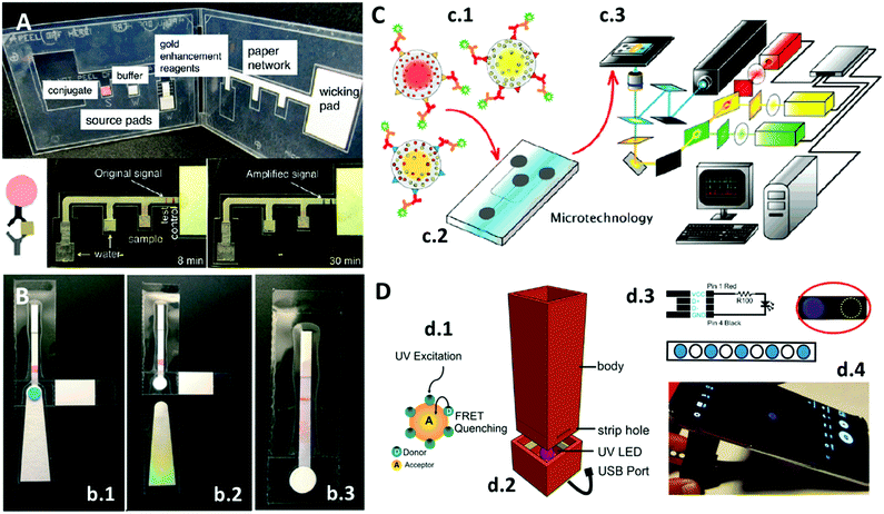 | ||
| Fig. 2 (A) PoC colorimetric device in which the signal of the LFB system is increased via a paper network consisting of paper pads storing the colour enhancement reagent. Adapted with permission from ref. 17, Copyright 2012 American Chemical Society. (B) LFB system to extract, amplify and detect nucleic acids: (b.1) sample is added on the sample port, (b.2) absorbent pad is removed after washing steps, and (b.3) after the addition of the amplification reagents, the purified analytes flow across the LFBs. Adapted with permission from ref. 18, Copyright 2016 Royal Society of Chemistry. (C) Multiplexed barcode system containing QDs: (c.1) QDs of different colours encapsulated into microbeads with specific biomarkers for different targets, (c.2) microfluidics system, and (c.3) detection platform. Adapted with permission from ref. 22, Copyright 2007 American Chemical Society. (D) Mobile phone integrated PoC system: (d.1) graphene QDs are quenched in the presence of acceptor compounds, (d.2) 3D-printed device with UV LED, (d.3) LED mechanism and paper substrate containing dried graphene QDs, and (d.4) mobile phone measuring the quenching of QDs. Adapted with permission from ref. 3, Copyright 2017 Nature Publishing Group. | ||
The application of nanopaper, also known as bacteria cellulose paper, is remarkable because it is produced by bacteria. As reported by Morales-Narváez et al.,20 0D nanoparticles can be stored and even produced on this colorless substrate resulting in plasmonic or fluorescent paper with great potential as an alternative to enzyme-linked immunosorbent assay (ELISA) plates. Their work demonstrated that PoC devices fabricated with nanopaper can take other forms besides ELISA plates such as cuvettes or simple spots on a piece of paper. Plasmonic resonance, fluorescence and quenching effects are some of the measurements that can be performed with these systems by using nanomaterials such as AgNPs, AuNPs and QDs. Similar to nanopaper, hydrogels can be used to store nanomaterials for use in PoC applications, which Yetisen et al.21 demonstrated with AgNPs and a phenylboronic acid-functionalized hydrogel. Their system could filter urine samples and retain glucose. Then, within five minutes a laser could measure the diffraction provoked by the interaction of the AgNPs and glucose. Surprisingly the system is reusable, unlike paper-based systems.
As previously mentioned, QDs are small 0D nanomaterials with fluorescent properties. Klostranec et al.22 utilized the intense signal of QDs to construct a multiplex system for the detection of different blood infectious disease-related targets using a “barcode” system (Fig. 2C). Different colored QDs were encapsulated into microbeads (Fig. 2c.1), and each bead was conjugated with antibodies specific to a different target, and the particles then were mixed inside a microfluidic system (Fig. 2c.2) with the sample. The incubation inside the microfluidics was controlled electrokinetically. Data collection was performed with software and a detection platform (Fig. 2c.3), which the authors claimed could be miniaturized for PoC diagnosis in the future. Their platform can identify independently the wavelength of each QD type, normalize it and, similarly to a barcode reading, estimate the amount of each target.
Another interesting work involving QDs was reported by Álvarez-Diduk et al.3 As shown in Fig. 2D, they took advantage of the fluorescence quenching effect occurring on graphene QDs in the presence of some polyphenolic compounds (Fig. 2d.1). They fabricated a 3D-printed dark chamber (Fig. 2d.2) with a UV LED powered by a mobile phone to excite the QDs (Fig. 2d.4). Using wax-printed traced spots on a paper strip, the QDs were physisorbed inside the spots to give an ELISA plate-like system (Fig. 2d.3). When polyphenolic compounds are dropped onto the spots, the fluorescence is quenched and captured by a mobile phone camera (Fig. 2d.4). The images can be analyzed directly on the mobile phone with an app or later with computer software.
2.2. 0D electrochemical-based PoC devices
Electrochemical measurements allow the identification of electrical phenomena related to a chemical change. The function of nanomaterials in this type of measurement is not limited to analyte labelling. Nowadays, nanoparticles are commonly used in commercial inks for the fabrication of electrodes. 0D nanomaterials as AuNPs or AgNPs and 1D nanomaterials such as carbon nanotubes (CNTs) are the most commonly used nanoparticles. As an example, da Silva et al.23 used commercial AgNPs to fabricate a miniaturized and portable Ag/AgCl reference electrode with a known and stable potential. They printed the electrode on two different flexible substrates, paper and polyethylene terephthalate (PET), using a high resolution piezoelectric inkjet material printer (Fig. 3A). After printing, the AgNPs ink was cured at 120 °C and treated with bleach (sodium hypochlorite, NaClO) to produce an Ag/AgCl mixture, which served as a pseudo reference electrode.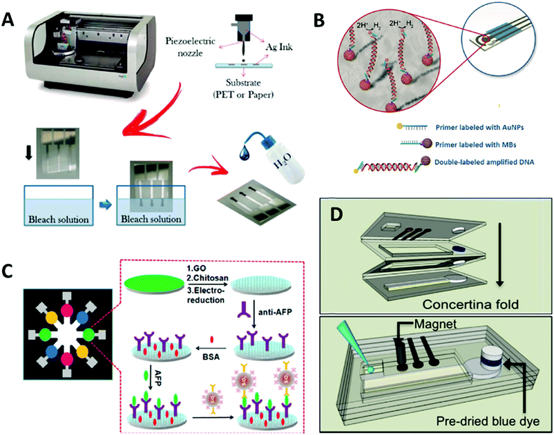 | ||
| Fig. 3 (A) Ag/AgCl reference electrodes fabricated from AgNPs using inkjet technology and bleach treatment. Adapted with permission from ref. 23, Copyright 2014 American Chemical Society. (B) Combination of AuNPs and MBs for the detection of DNA on an SPCE. Adapted with permission from ref. 25, Copyright 2015 John Wiley and Sons. (C) Paper PoC device for the electrochemical measurement of eight samples. Adapted with permission from ref. 30, Copyright 2013 American Chemical Society. (D) Paper origami PoC for the electrochemical detection of AgNPs. Unfolded (up) and folded (down). Adapted with permission from ref. 31, Copyright 2016 American Chemical Society. | ||
The reduction of silver is catalyzed by AuNPs, which in turn are extensively reported as transducers in electrochemical assays due to their high affinity to biological molecules.24 Another reaction that is often applied in electrochemistry and catalyzed by AuNPs is the hydrogen evolution reaction, which is the formation of H2 gas by the reduction of H+ ions. This reaction was measured by de la Escosura-Muñiz et al.25 who, combining DNA amplification strategies, magnetic beads (MBs) and AuNPs, developed a system on screen printed carbon electrodes (SPCE) that discriminates dog DNA from Leishmania parasite DNA hosted inside the cells. MBs and AuNPs are linked to the amplified DNA and, using a magnet, the conjugate is placed onto the working electrode of the SPCE for the signal to be measured efficiently (Fig. 3B). Iridium oxide nanoparticles (IrO2NPs) are another 0D nanomaterial used due to their catalytic properties towards the water oxidation reaction,26 which is the production of oxygen from water, and their application in impedimetric sensors.27,28 Impedance is a technique used to measure the frequency changes in the dielectric medium close to the nanoparticles. Thus, by binding biomarkers on IrO2 NPs, it is possible to detect variations in the conductivity of the medium depending on the capture of the biomarker by the target analyte.
Regarding AuNP-based LFBs, which are analogous to optical detection, some researchers are trying to integrate electrochemical sensing strategies into paper strips to achieve lower detection limits and higher sensitivity than colorimetric techniques.29 However, this requires the detection zone of the strips to be cut and dissolved in acid, thus the detection is performed with external electrodes on the dissolved nanoparticles. The addition of this extra step enhances the quantification on LFBs, but the methodology still needs to be improved either by including the step in an automated PoC device or by finding an alternative to dissolving part of the strip. A more user-friendly paper-based PoC tool was designed by Wu et al.,30 which permits the electrochemical analysis of eight samples sequentially (Fig. 3C). This device is comprised of eight electrodes pre-treated with antibodies specific to the target analyte. The samples are added to the electrodes and then SiO2 nanoparticles are dispensed on the electrodes (note that SiO2 nanoparticles are inexpensive and easy to load with various compounds such as dyes, proteins and enzymes). In this case, the SiO2 nanoparticles are loaded with antibodies specific to the analyte to perform a sandwich assay with horseradish peroxidase, the enzyme that triggers the electrochemical reaction. The electrodes are washed and then a reactive solution is added to the core of the device, which then flows to the electrodes, thereby activating an electrochemical reaction. Another interesting paper PoC device was fabricated by Cunningham et al.,31 an origami-styled system that as proof-of-concept was used for the detection of AgNPs by oxidizing them using a gold working electrode. The device consists of four folded paper layers (Fig. 3D), where the first layer contains the electrodes, inlet and outlet; the second and third layers contain a paper circuit delimited by wax and a blue dye that works as an indicator for the stoppage of the flow; and the forth layer contains a “sink” to redirect all the flow there.
2.3. 0D magnetic PoC devices
MBs and magnetic nanoparticles (MNPs) are often used as supports in PoC devices, usually in the washing and pre-concentration/amplification steps or in the precipitation of the analyte and other nanoparticles for example onto an electrode.25 Some researchers are also taking advantage of the magnetic properties of MNPs and use these as transducers32,33 by means of nuclear magnetic resonance (NMR). This technique is highly sensitive due to the low back-ground signal since non-magnetic substances exhibit no interference. In addition, NMR can detect all the tags present in the detection zone; whereas in optical and electrochemical sensors this is not always possible (in optical sensors, generally only the tags on the substrate surface are visible; and in electrochemical sensors, it is often required that the tags are in contact with the electrode to be able to generate a signal). In addition, the detection time is faster than electrochemical assays. However, NMR systems are expensive and may not be affordable to all possible users.Liong et al.32 proposed a microfluidics PoC device (Fig. 4) to detect amplified nucleic acids from a bacterium related to tuberculosis. The device can perform DNA amplification, MNPs-DNA incubation, washing and NMR detection. The device has three inlets for DNA, MNPs and washing buffer; some mixing channels for the incubation steps and an NMR coil that counts the amount of MNPs, which is proportional to the initial value of DNA concentration. As the main drawback in this device, although the NMR detection is fast, the amplification and incubation steps can prolong the duration of the assay by more than two hours. Anyhow, it is faster than other tuberculosis detection methods based on cell culture and microscopy. Chung et al.33 developed another NMR-based microfluidics PoC device, which they used for the detection of a biomarker in urine. Although its matrix is complex, the noise signal is low because non-magnetic substances do not interfere with the readout, as previously mentioned. Their device exhibited a LOD 8 times lower than a comparable reported colorimetric dipstick method.
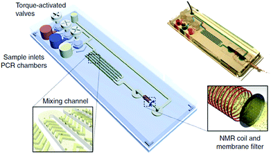 | ||
| Fig. 4 NMR-based microfluidic PoC device. Reprinted with permission from ref. 32, Copyright 2013 Nature Publishing Group. | ||
3. One-dimensional nanomaterials (1D)
1D nanomaterials are materials in which growth is oriented in one dimension, in a linear way. Their thickness can be as small as just one nanometer such as single-walled carbon nanotubes (SWCNTs), but their length could be a million times larger, such as hundreds of micrometers. The shape of these nanomaterials has an important effect on their application, where their length and diameter define their absorption wavelengths. Moreover, their length and thickness also grant mechanical strength, which is useful in the creation of larger nanostructured materials. Nonetheless, the growth of 1D nanomaterials is not simple and often requires meticulous synthetic routes that in turn determine their homogeneity.Nanowires are the simplest 1D nanomaterial, which can be created from other 0D nanomaterials or directly, and copper, nickel, silver, gold, platinum and silicone the most used elements. In the work of Mostafalu and Sonkusale,34 they introduced nanowires (made from platinum, nickel and copper) into paper substrates to create electrodes for electrocardiogram monitoring by means of tissue-electrode impedance, which work in dry conditions. This approach does not require the addition of an electrolytic gel between the electrodes and the skin, which is advantageous since gels dry quickly and are degraded with movement. The high surface area of the nanowires provides a good quality response in the electrodes, which ranged from 100 to 1 KΩ in the impedimetric measurements. Besides medical application, Mostafalu and Sonkusale demonstrated that the same paper electrodes worked properly as cathodes in an acidic battery.
In recent years, CNTs and SWCNTs have been widely used in electrochemical applications35–37 since these nanomaterials are highly conductive, both electrically and thermally. Additionally, CNTs are easily functionalized not only with biological compounds, but also with other nanomaterials (especially with metallic oxide nanoparticles), provoking an enhancement in their electrical properties, among others.35 CNTs have also been utilized in several commercial inks for the fabrication of screen printed electrodes (also, AgNPs are commonly used for the fabrication of reference electrodes and CNTs are used for the fabrication of counter and working electrodes36). In comparison to metallic nanowires, CNTs contribute to the fabrication of larger nanostructured materials with new properties such as high flexibility, elasticity and low weight since they are hollow inside. Also, CNTs are more robust than nanowires against temperature variations because the thermal expansion coefficient of carbon bonds is much lower than that in metals. However, it is important to consider that many reactions that can be applied on their surface will not be reversible, making the lifetime of CNTs shorter than other materials applied in sensing. As an example of the use of these materials, the work of Nemiroski et al.37 should be mentioned, where they integrated electrodes made with CNTs into a mobile phone system via the audio jack of the device (the audio jack has the advantage that it can send and receive information at the same time).
In a very smart way and for the first time, Azzarelli et al.5 used SWCNT to apply NFC technology for sensing. NFC technology can detect an antenna without requiring it to have an electrical power supply. This technology nowadays is present in most smartphone models, hotel door lock systems, metro stations, toys and even in mail stamps. Thus, NFC tags are becoming cheaper daily and easier to fabricate and modify. They tuned an NFC tag by replacing part of the circuit with SWCNTs, which by means of a chemiresistive reaction, alter the conductivity in the circuit depending on the presence of different compounds in the air, consequently making it act as an on/off logic gate inside the NFC tag (Fig. 5a). This technique was applied for the detection of compounds in the air, but for future PoC applications it can be used to detect analytes in the breath or probably even in bodily fluids such as blood and sweat.
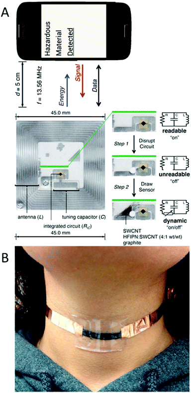 | ||
| Fig. 5 (A) NFC tag circuit modified with SWCNTs to work as an on/off logic gate in the presence of different analytes. Adapted with permission from ref. 5, Copyright 2014 National Academy of Sciences. (B) Chewing gum containing CNTs adapted for motion monitoring. Reprinted with permission from ref. 38, Copyright 2015 American Chemical Society. | ||
One more surprising use of CNTs was by Darabi et al. in chewing gum.38 They washed a chewing gum with water and ethanol and mixed it with a solution containing CNTs. Then, the mixture was stretched and folded several times in one direction to favor the orientation of the CNTs. This sensor worked properly for the detection of humidity in the medium (dryness of the mouth can be caused by certain medications or illnesses, by damage to the salivary glands or by hormonal changes) by measuring the electrical resistance in the gum. Also, as a motion sensor, as shown in Fig. 5b, it can detect not only body (neck in the figure) movements, but also the breath of the user. This device can be very interesting for PoC diagnostics (biting problems, dry mouth, and pulsations, and even take advantage of chemical reactions to detect different targets). However, there are two important drawbacks that preclude the introduction of the device into the mouth: its response is measured using electrical circuits and CNTs are currently classified as cytotoxic nanomaterials.
4. Single-layer nanomaterials (2D)
The compounds classified as 2D-nanomaterials can expand themselves in two directions and are composed of a monolayer of atoms or an ultrathin layer of a few atom. Albeit there exist several inorganic 2D nanomaterials, graphene has been by far the most used 2D material in the last years. Although graphene is considered a material composed of a single layer of atoms, it is quite difficult to find it in that state because it is usually found in groups of graphene layers. Depending on the number of layers, the electrical, optical and mechanical properties of graphene may differ. Other important parameters that affect the behavior of graphene are its oxidation level, the number of structural defects, purity degree, etc.,39 which can be controlled via its synthetic route.Graphene can be combined with QDs to work as a quencher (silencing the fluorescence signal of QDs when both are in contact). This property was harnessed for the fabrication of LFBs by Morales-Narváez et al.15 In their system, they dispensed two lines of QDs on a paper substrate, as the test and control, where the first line was capable of capturing some bacteria (by means of antibodies attached on QDs). After adding the sample on the LFBs, a solution of graphene oxide (GO) is added, which is the oxidized form of graphene containing epoxy bridges, carboxyl and hydroxyl groups. GO will turn off the fluorescence of the QDs in the control line and the test line if there are no bacteria in the sample. However, in presence of bacteria captured on the test line it will produce a gap between the GO and QDs, resulting in the emission of fluorescence. In comparison to traditional LFBs, this method prevents the formation of false positives during the assay since a negative sample will always turn off both lines (in the case where something external causes the test line not to be quenched, the control line will be also affected, obtaining an invalid strip but not a false positive). However, the assay time (more than 1 h) is longer than that for standard LFBs (usually of 5–10 min) due to the extra step of GO addition and drying, including the waiting time for the bacteria to flow across the strip.
Cheeveewattanagul et al.40 coated nanopaper with GO and introduced on this composite a suspension of antibodies attached to QDs. Again, the quenching effect keeps the fluorescence of the QDs silenced. Then, when an analyte (e.g. bacteria or proteins for which the antibodies are selective) is added, a gap is produced between the QDs and GO, negating the quenching effect and allowing fluorescence (Fig. 6). This technique is quite advantageous since it does not require washing steps, is portable and fast. Thus, it is a promising alternative to ELISA tests.
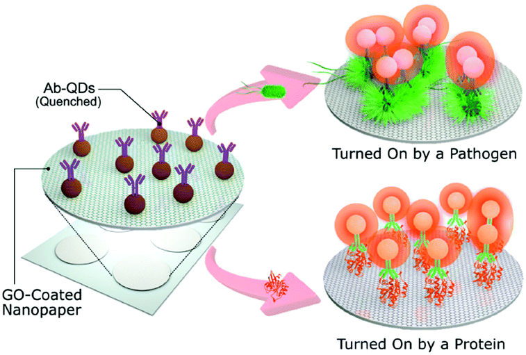 | ||
| Fig. 6 Nanopaper coated with GO. QDs can be stored inside remaining quenched but when the analyte, e.g. bacteria or proteins, is added fluorescence is observed. Adapted with permission from ref. 40, Copyright 2017 John Wiley and Sons. | ||
Owing to its electrical properties, graphene can be used for the fabrication of working electrodes.41,42 Antibodies can be conjugated onto the surface of graphene by coating pure graphene with polymers or by exploiting the chemistry of the carboxylic or hydroxyl groups in GO. Moreover, since graphene is planar, the antibodies can all be oriented perpendicularly to the graphene layer to increase the probability of capturing the analyte.41 Furthermore, graphene electrodes are sufficiently sensitive to allow label-free sensing, and small changes (i.e. electrochemical41,42 or impedimetric39,43 alterations) on the electrode surface are easy to detect. On the other hand, as a drawback, graphene demands highly meticulous control of its synthesis for reproducibility, especially regarding the number of layers and structural defects.
Baptista-Pires et al.43 designed a new solvent-free method for printing GO on different substrates using wax-printed patterns via printing on nitrocellulose membranes and vacuum filtration. GO remains on the non-wax-printed areas and is transferred to the target substrate by pressure. To demonstrate the possibilities of this technique, a touch sensor was printed, which was based on the resistance changes provoked by a finger in contact with the GO-printed circuit. This GO touch sensor is shown in Fig. 7A, which was connected to an LED and a power source (Fig. 7a.1), where the sensor works as a simple switch, turning on/off the LED (Fig. 7a.2 and a.3, respectively). This technology can be used to replace current touchscreens, which use controversial elements such as indium and rare-Earth metals,2 and in wearable PoC applications that require flexible devices (e.g. skin tattoo sensors34) or those based on contact-sensing (e.g. pressure or motion sensors38).
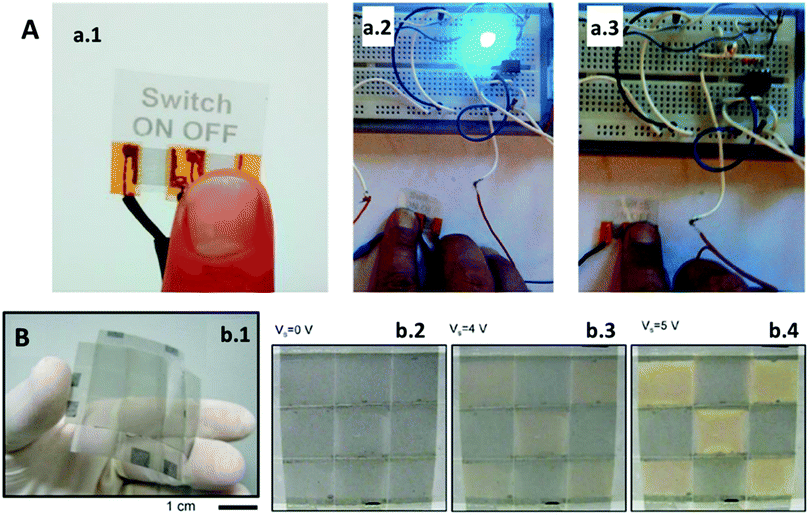 | ||
| Fig. 7 (A) GO tactile device: (a.1) GO switch works by skin contact turning a LED from (a.2) ON to (a.3) OFF status. Adapted with permission from ref. 43, Copyright 2016 American Chemical Society. (B) Electrochromic device composed of (b.1) flexible graphene electrodes whose transmittance increases when a current is applied: (b.2) 0 V and (b.3 and b.4) chess pattern visible at a higher voltage. Adapted with permission from ref. 44, Copyright 2014 Nature Publishing Group. | ||
Besides its mentioned characteristics, graphene is also an electrochromic material, and it can be tuned to change its colour in a reversible way depending on the current supplied. Polat et al.44 developed different electrochromic flexible devices using this property. In one of their devices they attached two plastic substrates coated on one side with graphene electrodes and a liquid electrolyte in between. When a voltage is applied across the electrodes, graphene turns translucent because the voltage is enough to penetrate the graphene layers creating structural defects, which fade its characteristic black colour. Their final device is shown in Fig. 7B, which was fabricated using various graphene electrodes. The device is flexible (Fig. 7b.1) and graphene can resist curvature with a 1 cm radius without being damaged. By applying different voltages on some of the electrodes, they create a chess pattern since transmittance is increased on the layers where the current is increased, including 0 V (Fig. 7b.2), 4 V (Fig. 7b.3), and 5 V (Fig. 7b.4). Thanks to this technology, electrochemical signaling can be converted into optical responses in situ, resulting in more user-friendly wearable PoC devices.
5. Other nanomaterials (3D)
There are an extensive variety of 3D materials varying both in shape and size, which lead to different possibilities in the final sensing application. Non-spherical nanoparticles exhibit properties quite similar to 0D nanomaterials; however, changes in shape often lead to absorbance changes (i.e. the colour of a solution of gold nanospheres may be different from a solution of nanocubes or nanotriangles, even when their chemical composition and size are the same). Taking advantage of this fact, plasmonic-based PoC sensors can be fabricated, such as that reported by Fu et al.4 Their device is portable and can be coupled into a mobile phone, using its light sensor, which is included on most modern mobile phones to improve their photograph quality or control the screen brightness. The device consists of a plate, where the sample is added, and an LED, which illuminates the sample in the plate and reaches the light sensor. To demonstrate the capabilities of their device they used it to measure the plasmonic changes occurring on triangular silver nanoprisms in the absence of a cancer biomarker. This is an indirect detection method, which triggers a shape transformation in the nanoparticles with hydrogen peroxide. Li et al.45 also used a 3D silver nanomaterial, nanoporous silver, which can be used as signal enhancer, label and metallic ion carrier. Their system consists of a multiplex electrochemical origami paper device (Fig. 8) that uses nanoporous silver loaded with different metallic ions as labels for tumor sensing. A silver electrode is used as the reference electrode (Fig. 8A) and screen-printed carbon electrodes as the counter and working electrodes (Fig. 8B). This paper device can be folded (Fig. 8C) and integrated into an electrical circuit (Fig. 8D).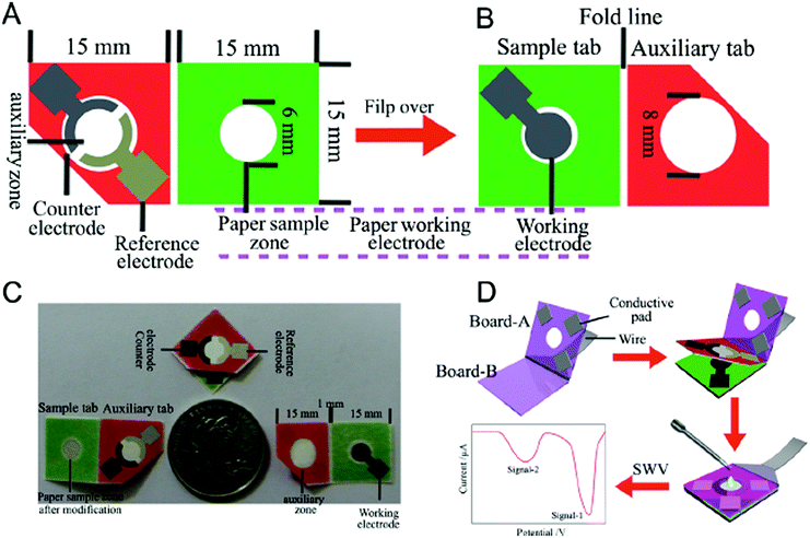 | ||
| Fig. 8 Multiplex electrochemical origami paper device: (A) front part: silver reference electrode and carbon counter electrode; (B) back part: carbon working electrode; (C) size comparison of the device and (D) its application for electrochemical measurements. Adapted with permission from ref. 45, Copyright 2014 Elsevier. | ||
Some non-spherical nanoparticles exhibit electrochromic properties such as the WO3 nanoparticles used by Marques et al.46 on a paper substrate. The nanoparticles change from yellow to blue in the presence of electrochemically active bacteria. Thus, this is a simple sensor that functions similarly to ELISA assays but without time-consuming steps or the use of delicate reagents (i.e. biological reagents have short expiration dates; whereas, nanomaterials can last long periods of time, even when stored at room temperature). Photonic crystals (PC) are other example of electrochromic materials often composed of other nanoparticles, which are assembled following a crystalline pattern. These nanomaterials demonstrate good adaptability in different types of sensors due to their resistance to being bent,47 and are used in microfluidic systems both in polymeric channels48 and paper,49 which permit label-free sensing (a colour change occurs when the analyte attaches or passes near the PC). Cullen et al.50 converted PC into simple PoC wearable stickers that can be settled on clothes to warn its user in a war zone about possible aftermaths related to the expansive wave of a blast (Fig. 9). PC are broken when subjected to high pressure as consequence of an explosion thus changing their colour, which notifies the user that the blast may have induced non-visible injuries such as internal trauma or brain damage.
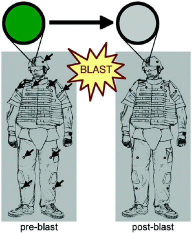 | ||
| Fig. 9 PC-based wearable that changes colour in response to the shock wave of a blast. Reprinted with permission from ref. 50, Copyright 2011 Elsevier. | ||
6. Conclusions
Daily, PoC devices are becoming indispensable tools for diagnostics, which are required not only by medical specialists at hospitals or the doctor's office but anyone, even at home or outdoors. Although most of the discussed devices are only demonstrated as proof-of-concept, it is clearly shown that nanomaterials exhibit several advantages when integrated in PoC systems.Table 1 summarizes the different nanomaterial types, with the most common examples of each classification, the possible detection methods that the final PoC can employ and some of the strengths and weaknesses in each case. Depending on the properties of the nanomaterials and the way they are integrated within PoC devices, various detection technologies can be used, where optical and electrochemical detection are the most reported.
| Nanomaterial type | Examples of nanomaterials | PoC detection principle | Advantages | Disadvantages |
|---|---|---|---|---|
| 0D | • AuNPs | • Optical | • Simple synthetic procedures | • No special structural properties |
| • AgNPs | • Fluorescent | • Small size | • Some 0D nanomaterials can easily agglomerate | |
| • QDs | • Electrochemical | • Easy to bioconjugate | ||
| • UPCs | • Magnetic | • Adaptable into other nanomaterials | ||
| • Magnetic nanoparticles | ||||
| 1D | • Nanowires | • Electrochemical | • Highly conductive | • Complex synthesis |
| • CNTs | • Motion | • Orientable | • Difficult to control their shape | |
| • Structurally resistant | ||||
| 2D | • Graphene | • Electrochemical | • Easy to modify | • Difficult to separate a single graphene sheet |
| • Fluorescence | • Flexible | • Structural defects are common | ||
| • Tactile | • Fluorescence quencher | |||
| 3D | • Non-spherical nanoparticles | • Optical | • Can combine the properties of other nanomaterials | • Like 0D nanomaterials, 3D nanomaterials can easily agglomerate |
| • PCs | • Electrochemical | • Tunable optical properties | • Usually, not as small as 0D nanomaterials | |
Although electrical techniques employing nanomaterials as electrodes or electrocatalysts are well-known to exhibit higher sensitivity and lower detection limits, optical techniques are emerging given their simplicity and easy integration in paper/plastic platforms, including easy and efficient coupling with smartphones.
The synergy of nanomaterials with a variety of biosensing systems and communication technologies is excepted to yield innovative PoC systems that may develop from research labs to fulfil the ASSURED (Affordable, Sensitive, Specific, User-friendly, Rapid & Robust, Equipment-free and Deliverable to end-users) criteria by the WHO6 for applications in diagnostics.
Conflicts of interest
There are no conflicts of interest to declare.Acknowledgements
The ICN2 is funded by the CERCA Programme/Generalitat de Catalunya. The ICN2 is supported by the Severo Ochoa program of the Spanish Ministry of Economy, Industry and Competitiveness (MINECO, grant no. SEV-2013-0295). We acknowledge support from the Spanish MINECO under project PCIN-2016-066 (program Euronanomed 2). This work has been done in the framework of PhD Programme in Chemistry of Universitat Autònoma de Barcelona.References
- M. A. Burns, Science, 2002, 296, 1818–1819 CrossRef PubMed.
- D. Quesada-González and A. Merkoçi, Biosens. Bioelectron., 2017, 92, 549–562 CrossRef PubMed.
- R. Álvarez-Diduk, J. Orozco and A. Merkoçi, Sci. Rep., 2017, 7, 976 CrossRef PubMed.
- Q. Fu, Z. Wu, F. Xu, X. Li, C. Yao, M. Xu, L. Sheng, S. Yu and Y. Tang, Lab Chip, 2016, 16, 1927–1933 RSC.
- J. M. Azzarelli, K. A. Mirica, J. B. Ravnsbæk and T. M. Swager, PNAS, 2014, 111(51), 18162–18166 CrossRef PubMed.
- A. K. Yetisen, M. S. Akram and C. R. Lowe, Lab Chip, 2013, 13, 2210–2251 RSC.
- D. Quesada-González and A. Merkoçi, Biosens. Bioelectron., 2015, 73, 47–63 CrossRef PubMed.
- M. Sher, R. Zhuang, U. Demirci and W. Asghar, Expert Rev. Mol. Diagn., 2017, 17(4), 351–366 CrossRef PubMed.
- J. N. Tiwari, R. N. Tiwari and K. S. Kim, Prog. Mater. Sci., 2012, 57, 724–803 CrossRef.
- M. Perfézou, A. Turner and A. Merkoçi, Chem. Soc. Rev., 2012, 41, 2606–2622 RSC.
- M. Wuithschick, A. Birnbaum, S. Witte, M. Sztucki, U. Vainio, N. Pinna, K. Rademann, F. Emmerling, R. Kraehnert and J. Polte, ACS Nano, 2015, 9(7), 7052–7071 CrossRef PubMed.
- S. Birnbaum, C. Udén, C. G. M. Magnusson and S. Nilsson, Anal. Biochem., 1992, 206, 168–171 CrossRef PubMed.
- R. H. Shyu, H. F. Shyu, H. W. Liu and S. S. Tang, Toxicon, 2002, 40, 255–258 CrossRef PubMed.
- C. W. Yen, H. de Puig, J. Tam, J. Gómez-Márquez, I. Bosch, K. Hamad-Schifferli and L. Gehrke, Lab Chip, 2015, 15(7), 1638–1641 RSC.
- E. Morales-Narváez, T. Naghdi, E. Zor and A. Merkoçi, Anal. Chem., 2015, 87, 8573–8577 CrossRef PubMed.
- P. L. A. M. Corstjens, C. J. de Dood, D. Kornelis, E. M. T. K. Fat, R. A. Wilson, T. M. Kariuki, R. K. Nyakundi, P. T. Loverde, W. R. Abrams, H. J. Tanke, L. V. Lieshout, A. M. Deelder and G. J. Van Dam, Parasitology, 2014, 141, 1841–1855 CrossRef PubMed.
- E. Fu, T. Liang, P. Spicar-Mihalic, J. Houghtaling, S. Ramachandran and P. Yager, Anal. Chem., 2012, 84, 4574–4579 CrossRef PubMed.
- N. M. Rodriguez, W. S. Wong, L. Liu, R. Dewar and C. M. Klapperich, Lab Chip, 2016, 16, 753–763 RSC.
- G. E. N. Pauli, A. de la Escosura-Muñiz, C. Parolo, I. H. Bechtold and A. Merkoçi, Lab Chip, 2015, 15, 399 RSC.
- E. Morales-Narváez, H. Golmohammadi, T. Naghdi, H. Yousefi, U. Kostiv, D. Horák, N. Pourreza and A. Merkoçi, ACS Nano, 2015, 9(7), 7296–7305 CrossRef PubMed.
- A. K. Yetisen, Y. Montelongo, F. da Cruz Vasconcellos, J. L. Martinez-Hurtado, S. Neupane, H. Butt, M. M. Qasim, J. Blyth, K. Burling, J. B. Carmody, M. Evans, T. D. Wilkinson, L. T. Kubota, M. J. Monteiro and C. R. Lowe, Nano Lett., 2014, 14, 3587–3593 CrossRef PubMed.
- J. M. Klostranec, Q. Xiang, G. A. Farcas, J. A. Lee, A. Rhee, E. I. Lafferty, S. D. Perrault, K. C. Kain and W. C. W. Chan, Nano Lett., 2007, 7(9), 2812–2818 CrossRef PubMed.
- E. T. S. G. da Silva, S. Miserere, L. T. Kubota and A. Merkoçi, Anal. Chem., 2014, 86, 10531–10534 CrossRef PubMed.
- S. J. Park, T. A. Taton and C. A. Mirkin, Science, 2002, 295, 1503–1506 CrossRef PubMed.
- A. de la Escosura-Muñiz, L. Baptista-Pires, L. Serrano, L. Altet, O. Francino, A. Sánchez and A. Merkoçi, Small, 2016, 12(2), 205–213 CrossRef PubMed.
- L. Rivas, A. de la Escosura-Muñiz, J. Pons and A. Merkoçi, Electroanalysis, 2014, 26(6), 1287–1294 CrossRef.
- L. Rivas, C. C. Mayorga-Martínez, D. Quesada-González, A. Zamora, A. de la Escosura-Muñiz and A. Merkoçi, Anal. Chem., 2015, 87(10), 5167–5172 CrossRef PubMed.
- C. C. Mayorga-Martinez, A. Chamorro-García, L. Serrano, L. Rivas, D. Quesada-González, L. Altet, O. Francino, A. Sánchez and A. Merkoçi, J. Mater. Chem. B, 2015, 3, 5166–5171 RSC.
- X. Mao, M. Baloda, A. S. Gurung, Y. Lin and G. Liu, Electrochem. Commun., 2008, 10, 1636–1640 CrossRef.
- Y. Wu, P. Xue, Y. Kang and K. M. Hui, Anal. Chem., 2013, 85, 8661–8668 CrossRef PubMed.
- J. C. Cunningham, M. R. Kogan, Y. J. Tsai, L. Luo, I. Richards and R. M. Crooks, ACS Sens., 2016, 1, 40–47 CrossRef.
- M. Liong, A. N. Hoang, J. Chung, N. Gural, C. B. Ford, C. Min, R. R. Shah, R. Ahmad, M. Fernandez-Suarez, S. M. Fortune, M. Toner, H. Lee and R. Weissleder, Nat. Commun., 2013, 4, 1752 CrossRef PubMed.
- H. J. Chung, K. L. Pellegrini, J. Chung, K. Wanigasuriya, I. Jayawardene, K. Lee, H. Lee, V. S. Vaidya and R. Weissleder, PLoS One, 2015, 10(7), e0133417 Search PubMed.
- P. Mostafalu and S. Sonkusale, RSC Adv., 2015, 5, 8680–8687 RSC.
- A. Ali, P. R. Solanki, S. Srivastava, S. Singh, V. V. Agrawal, R. John and B. D. Malhotra, ACS Appl. Mater. Interfaces, 2015, 7, 5837–5846 Search PubMed.
- S. Teixeira, R. S. Conlan, O. J. Guy and M. G. F. Sales, Electrochim. Acta, 2014, 136, 323–329 CrossRef.
- A. Nemiroski, D. C. Christodouleas, J. W. Hennek, A. A. Kumar, E. J. Maxwell, M. T. Fernández-Abedul and G. M. Whitesides, PNAS, 2014, 111(33), 11984–11989 CrossRef PubMed.
- M. A. Darabi, A. Khosrozadeh, Q. Wang and M. Xing, ACS Appl. Mater. Interfaces, 2015, 7, 26195–26205 Search PubMed.
- E. Morales-Narváez, L. Baptista-Pires, A. Zamora-Gálvez and A. Merkoçi, Adv. Mater., 2017, 29, 1604905 CrossRef PubMed.
- N. Cheeveewattanagul, E. Morales-Narváez, A. R. H. A. Hassan, J. F. Bergua, W. Surareungchai, M. Somasundrum and A. Merkoçi, Adv. Funct. Mater., 2017, 27, 1702741 CrossRef.
- S. Teixeira, R. S. Conlan, O. J. Guy and M. G. F. Sales, J. Mater. Chem. B, 2014, 2, 1852–1865 RSC.
- S. K. Tuteja, Priyanka, V. Bhalla, A. Deep, A. K. Paul and C. R. Suri, Anal. Chim. Acta, 2014, 809, 148–154 CrossRef PubMed.
- L. Baptista-Pires, C. C. Mayorga-Martínez, M. Medina-Sánchez, H. Montón and A. Merkoçi, ACS Nano, 2016, 10, 853–860 CrossRef PubMed.
- E. O. Polat, O. Balcı and C. Kocabas, Sci. Rep., 2014, 4, 6484 CrossRef PubMed.
- W. Li, L. Li, S. Ge, X. Song, L. Ge, M. Yan and J. Yu, Biosens. Bioelectron., 2014, 56, 167–173 CrossRef PubMed.
- A. C. Marques, L. Santos, M. N. Costa, J. M. Dantas, P. Duarte, A. Gonçalves, R. Martins, C. A. Salgueiro and E. Fortunato, Sci. Rep., 2015, 5, 9910 CrossRef PubMed.
- X. Xu, H. Subbaraman, S. Chakravarty, A. Hosseini, J. Covey, Y. Yu, D. Kwong, Y. Zhang, W. C. Lai, Y. Zou, N. Lu and R. T. Chen, ACS Nano, 2014, 8(12), 12265–12271 CrossRef PubMed.
- C. J. Choi and B. T. Cunningham, Lab Chip, 2007, 7, 550–556 RSC.
- B. R. Schudel, C. J. Choi, B. T. Cunningham and P. J. A. Kenis, Lab Chip, 2009, 9, 1676–1680 RSC.
- D. K. Cullen, Y. Xu, D. V. Reneer, K. D. Browne, J. W. Geddes, S. Yang and D. H. Smith, NeuroImage, 2011, 54, S37–S44 CrossRef PubMed.
| This journal is © The Royal Society of Chemistry 2018 |


