
 Open Access Article
 This Open Access Article is licensed under a
 Creative Commons Attribution 3.0 Unported Licence
The excess electron in polymer nanocomposites†
Fernan
Saiz
 and
Nick
Quirke
*
and
Nick
Quirke
*
Department of Chemistry, Imperial College, London, UK. E-mail: n.quirke@ic.ac.uk
First published on 29th October 2018
Abstract
We have used ab initio molecular dynamics and density-functional theory (DFT) calculations at the B3LYP/6-31G** level of theory to evaluate the energy and localisation of excess electrons at a number of representative interfaces of polymer nanocomposites. These modelled interfaces are made by combining liquid water and amorphous slabs of polyethylene and silica. The walls of the amorphous silica slabs are built with two surface chemistries: Q4 or fully-dehydroxylated and Q3/Q4 or partially-hydroxylated with a silanol content between 1.62 and 6.86 groups per nm2. Our results indicate that in silica/polyethylene systems an excess electron would sit at the interface with energies between −1.75 eV with no hydroxylation and −0.99 eV with the highest silanol content. However, in the presence of a free water film, the chemistry of the silica surface has a negligible influence on the behaviour of the excess electron. The electron sits preferentially at the water/vapour interface with an energy of minus a few tenths of an eV. We conclude that the moisture content in a wet polymer nanocomposite has a profound influence on the electron trapping behaviour as it produces much lower trapping energies and a higher excess-electron mobility compared to the dry material.
I. Introduction
Electron transfer underpins technologies such as photovoltaics,1,2 organic thin film transistors, light-emitting diodes,3 photocatalysis,4 DNA based molecular electronics,5,6 as well as energy transfer in nature7 including radiation damage and repair.8,9 The injection of excess electrons plays a major role in the performance of electrical insulation with significant economic consequences.10 Polymers are commonly employed as insulators in electric and electronic devices such as capacitors,11–13 transistors,14,15 fuel cell membranes,16,17 and in high-voltage cables.18 When polymers are used for high-voltage cables their insulating properties such as the electrical conductivity or breakdown strength degrade over time due to exposure to heat, light, moisture, surfactants, mechanical stress, and high electric fields.19,20 This degradation process is thought to be related to the trapping processes of charge carriers, the so-called space charge.19It has been suggested that the insulating properties of polymers can be improved by the addition of nanoparticles to form nanocomposites: a homogeneously-dispersed blend of a dielectric material with a filler whose particles have radii of up to a few tens of a nanometre.21 Polymer nanocomposites made by blending a polymer with oxide nanoparticles have been reported to have higher effective permittivities,22,23 and enhanced electrical breakdown strength24 than those of the base polymer. It is thought this enhancement is a consequence of a reduction of injected (excess) electron mobility caused by trapping at the new interfaces created by the presence of nanoparticle surfaces, in addition to those already present in the base polymer (through nanovoids25 and chemical defects and impurities26). In polyethylene, the addition of nanoparticles has been shown to suppress space charge.27
A common choice of nanoparticle additive is silicon oxide (SiO2). Thermally grown oxides on silicon and silicon carbide supports exhibit high electric breakdown field strengths of up to 9.2 MV cm−1.28 Photon stimulated tunnelling (PST) of electrons at the Si/SiO2 interface show the presence of very deep electron traps of 2.77 ± 0.05 eV (below the conduction band).29 Electron trapping is known to have a dramatic effect on the performance and reliability of electronic devices employing silicon dioxide as gate insulators and in charge trap flash memory devices.30,31 While it is clear that addition of silica nanoparticles changes the electrical characteristics of polymer nanocomposites, there is some doubt as to whether these effects are due to the presence of nanoparticles (with or without a surface coating) or due to water adsorption or entrained solvent associated with the creation of the nanocomposite.32
Therefore, the goal of this work is to study the properties of excess electrons at a number of interfaces relevant to nanocomposites by combining amorphous polyethylene, water, and amorphous silica phases using density functional theory (DFT). Our aim is to understand at a fundamental level the nanoscopic processes underlying the experimental data discussed above, in particular the possible role of water. This DFT work significantly extends our previous studies of pure polyethylene25,26,33–35,41 to encompass mixtures.
In the past DFT has been used to study the degree of localisation of excess electrons at polyethylene interfaces36,37 and in bulk38,39 by assuming that the excess electron can be described by Kohn–Sham orbitals. However, it has been unclear to what extent the use of these orbitals could be justified40 to model excess electrons, especially when employing hybrid functionals as the Koopmans’ theorem is only valid for closed-shell Hartree–Fock theory. Nevertheless, we have recently used the all-electron CRYSTAL1759 code at the B3LYP level of theory to compare the representation of an excess electron in polyethylene in bulk and its vacuum interfaces by the lowest-unoccupied molecular orbital (LUMO) of a N electron system and the highest-occupied molecular orbital (HOMO) of an N + 1 system (the +1 electron balanced by a uniform background charge).41 These two representations have also been compared with the single-electron Lanczos behaviour34 employing an excess electron-polyethylene pseudopotential fitted34 to experimental data for the bottom of the conduction band of alkanes measured with respect to vacuum. Although both orbitals localise excess electrons at similar positions in the interface and have similar localisation lengths, the excess electron energy predicted by the LUMO(N) corrected to a zero at the vacuum level, agrees best with the Lanczos’ for the larger vacuum gaps41 and hence will be used in this work.
The surface chemistry of nanoparticles used to create nanocomposites affects the dispersion of nanoparticles in a polymer matrix as well as the measured electrical properties. Thus, we vary the silica surface chemistry in this study to make it more or less hydrophilic. A silica surface can be characterised by the coordination number Qn of the surface silicon atoms. We create both Q3 and Q4 amorphous surfaces. On a Q4 surface all dangling silicon atoms are bridged with four oxygen neighbours, similarly, on a Q3 surface silicon atoms are connected with three oxygen neighbours and a hydroxyl group –OH (silanol). The Q4 surface is obtained experimentally by calcination of Q3 and Q2 surfaces at 900 K42 and is hydrophobic with a heat of immersion of 22 mN m−1 whereas the silanated surfaces are hydrophilic.43 We also consider the effect of adding a free water film to the silica surface and the role of silanols formed spontaneously in the ab initio simulations.
The manuscript is organised as follows. In Section II, we briefly describe the methods employed to build the bulk and interfacial systems and the parameterisation of the DFT calculations. Given the large amount of detail, we present the full methodology in the ESI.† In Section III, we present the degrees of localisation and energies of excess electrons in bulk systems and for the interfacial systems of amorphous polyethylene and water, amorphous polyethylene and silica, and water and amorphous silica. In Section IV, we compare the excess electron properties in bulk and at interfaces, we also predict the valence and conduction band offsets at the interfaces. Finally, Section V concludes our main findings and looks at the implications for future work.
II. Simulation methods
In this section we describe the main procedures used to prepare the systems of amorphous polyethylene, amorphous silica, and liquid water, and their interfaces as well as the ab initio calculations to obtain their excess-electron properties. Full details are given in Section SI of the ESI.†Slabs of amorphous silica are prepared in a two-stage process. In the first stage, we use the classical molecular package LAMMPS44 to generate a bulk system made with 3 × 3 × 2 unit cells in the beta-cristobalite lattice. We then follow a melting-quench process to yield an amorphous cube with a density of 2.18 g cm−3, close to the experimental value of 2.20 g cm−3.45 The resulting configuration is then imported to the Materials Studio package,46 where a vacuum gap of 2 nm is imposed in the z-direction to create two surfaces. We then bridge a small number of Si atoms to four O atoms on the surface and in the inner regions of the slab. We next optimise the geometry with the COMPASS247 force field available in the Forcite Module and then with the DFTB+ Module and finally with ab initio package CP2k48 in its QUICKSTEP49 implementation. CP2k uses GTH pseudopotentials50,51 and double-ζ basis sets with polarization functions (DZVP) as well as Grimme scheme52 to include long-range forces. This bridging and optimisation is repeated until the surface is stable at which point we run an ab initio molecular dynamics simulation with CP2k with a timestep of 0.25 × 10⁻³ ps. The final Q4 (no dangling silanol Si–OH groups) surface has a cross section of 1.578 nm × 1.572 nm in the y and z directions and a length of 2.475 nm in the x-direction. We believe that this length is sufficiently long to reproduce bulk-like conditions in the inner layers of this silica slab as Goumans et al.53 showed that a slab of quartz-silica with a thickness of 1.125 nm is sufficiently large to represent bulk-like behaviour in the innermost layers. We use this Q4 surface to create others with Q3/Q4 chemistries, in which a few Si–O are broken in the Q4 surface and replaced with silanol Si–OH groups with concentrations of up to 6.86 groups per nm2.54 Once the silanol groups are built, the slabs are optimised with CP2k and run with ab initio molecular dynamics again.
The amorphous polyethylene systems are also prepared using the Materials Studio software using four chains of 40 carbons with the COMPASS2 force field. The amorphous solid has the same cross section as the amorphous silica slab and a depth of 1.76 nm. Chains are not allowed to cross the boundaries in the x direction to avoid splitting the chains when a vacuum gap of 2.0 nm is imposed (see later) though periodic boundary conditions are still applied in all three directions. These configurations are then relaxed with CP2k with the local-density approximation (LDA) and the long-range forces are described by the Dion–Rydberg–Schroeder–Langreth–Lundqvist (DRSLL) nonlocal van der Waals density functional.55 After the structure is optimised, we run a short ab initio molecular dynamics simulation of 1 ps to further relax the structure.
Finally, ensembles of liquid water at 300 K are first prepared using the TIP04/2005 model,56 which gives excellent density predictions at 278 K. The system is composed of 150 molecules, occupying a parallelepiped region with the same cross section as the silica and polyethylene samples. We next run an ab initio molecular dynamics simulation with CP2k for 25 ps with a timestep of 0.25 × 10⁻³ ps to relax the bond lengths with the PBE57 functional revised for small molecules (revPBE58) in the bulk and, with a vacuum gap of 2.0 nm, to create a water/vapour interface. We have used the revPBE functional because from simulations with a cubic system of 343 molecules at constant temperature 300 K and pressure of 1 bar, we have found that this revised form improves significantly the agreement with the experimental density with respect to the original parameterisation PBE: the disagreement is only 3.9% using revPBE, whereas it deviates up to 13.4% with PBE. Note though that the high computational cost of these ab initio molecular dynamics calculations restricts the length of time for which we can simulate these water systems. One ps of simulated time with CP2k needs to be run on 64 processors for nearly 10 hours for the bulk phase and 13 hours with the 2.0 nm vacuum gap.
Once the pure systems have been prepared, we build interfaces of water/polyethylene, silica/polyethylene, and silica/water/silica. The first is prepared with no vacuum using the revPBE functional and Grimme scheme. The second is prepared with and without a 2.0 nm vacuum gap, which requires the LDA/DRSLL setup for the former and the PBEsol59/Grimme for the latter. The use of LDA is justified because the polymer chains evaporate after a few ps of simulation. The third type of interface is prepared with the same vacuum gap and employs the revPBE functional. Once the computational setup is ready, the geometry of each two-component system is optimised with CP2k to avoid undesirable orbital overlap between the atoms at each surface. Thanks to this optimisation, the simulations require a shorter time to equilibrate. The systems are run in C2PK for 7.5 ps for polyethylene/silica and 15 ps for polyethylene/water and 15 ps for water/silica/water to obtain a sufficient number of configurations with a timestep of 0.25 × 10⁻³ ps.
The resulting configurations from the ab initio molecular dynamics run are then used by the all-electron CRYSTAL17 DFT code60 to obtain their excess-electron properties. The DFT calculations are carried out using the hybrid B3LYP exchange–correction functional, which as shown in our previous work41 is able to reproduce the experimental band gap of crystalline polyethylene and the energy and degree of spatial localisation of excess electrons in amorphous polyethylene. A standard all-electron 6-31G**61,62 basis set is used to represent the local atomic orbitals in terms of primitive Cartesian Gaussian functions. Polarization functions (p-functions for hydrogens and d-functions for carbons, oxygens, and silicons) are used to ensure that the orbitals can distort from their original atomic symmetry, and to adapt to the molecular surroundings leading to a better prediction of the total energy of the system with high hydrogen content.63 The size of the systems allows us to restrict the reciprocal space integrations to the Γ-point of the Brillouin zone and ground-state energy convergence is enforced at 1 × 10⁻⁶ Ha. We have used the default parameters in CRYSTAL17 to calculate the two-electron coulombic and exchange integrals.
Periodic boundary conditions are imposed on the x, y, z directions in systems with no vacuum using the keyword CRYSTAL and on the x and y directions in systems with a 2.0 nm vacuum gap using the keyword SLAB. We refer hereinafter as ‘3D-periodic’ to the first type of simulations and ‘2D-slab’ to the second. We use this second type of calculations in systems where surface dipoles are present, such as liquid water or silica slabs with hydroxylated walls, to obtain a well-defined vacuum level, where the zero of the electrostatic potential Vz is defined by the CRYSTAL code in such a way that Vz(+∞) = −Vz(−∞). See, for example, the case with a slab of amorphous silica with a silanol surface concentration of 1.61 nm−2 in Fig. S1 in the ESI.† In this case, the permanent dipole in the silica slab divides the space in two parts, with higher and lower potential, having two equally valid vacuum states. An electron extracted from the material will chose the side with a positive potential to have a negative (minimum) potential energy in the vacuum. Hence, we correct the energies of the LUMO using
| LUMOcorrected = LUMOuncorrected − e〈Vz〉vacuum, | (1) |
LUMOcorrected = LUMOuncorrected − (Eband![[thin space (1/6-em)]](https://www.rsc.org/images/entities/char_2009.gif) 1,bulk-like − Eband1,bulk) − e〈Vz〉vacuum, 1,bulk-like − Eband1,bulk) − e〈Vz〉vacuum, | (2) |
1,bulk-like and Eband1,bulk corresponds the core-level shift of the energies of the band 1 in the bulk case and the bulk-like region from a second simulation with a 2.0 nm vacuum gap with a Q4 surface. Eqn (2) is also applied to obtain excess electron energies for amorphous polyethylene slabs.
III. Results and discussion
III. 1. Pure systems of silica and water
Before studying the interfacial systems, we first analyse the behaviour of excess electrons in bulk water and silica, as represented by the LUMO of our N-electron system. This analysis complements our recent work on bulk amorphous polyethylene and its vacuum interfaces.41 In bulk polyethylene an excess electron localises in naturally occurring nanovoids25 with radii less than 0.4 nm. In the presence of large empty gaps between planar amorphous slabs, the excess electron localises on the unfilled side of the polyethylene surface, its density peaking at 0.2 nm into the vacuum with a localisation length of 0.34 nm and an energy of around −0.2 eV in good agreement with single-electron methods.For pure silica, a 3D-periodic calculation with CRYSTAL17 predicts that 80% of the LUMO's charge sits in a small cavity between atomic rings in the bulk phase as shown in Fig. 1. We obtain a corrected DFT excess electron energy of −1.54 eV for the 3D-periodic and −1.43 eV for the 2D-slab calculations (see Table 1). This strong localisation in the bulk of amorphous silica has been also observed in other DFT studies using plane waves64 which predict a comparable excess electron localisation energy of −1.25 eV. Our 2D-slab calculations allow us to investigate the effect of adding silanol groups on the silica walls. The results in Table 1 indicate the LUMO energy increases with increasing surface hydroxylation, which suggests that the electron prefers to move away from the hydroxyl groups. This preference has been also observed in polycrystalline MgO, where hydroxyl groups form shallower and more diffuse electron traps than those created on the dehydroxylated surface.65
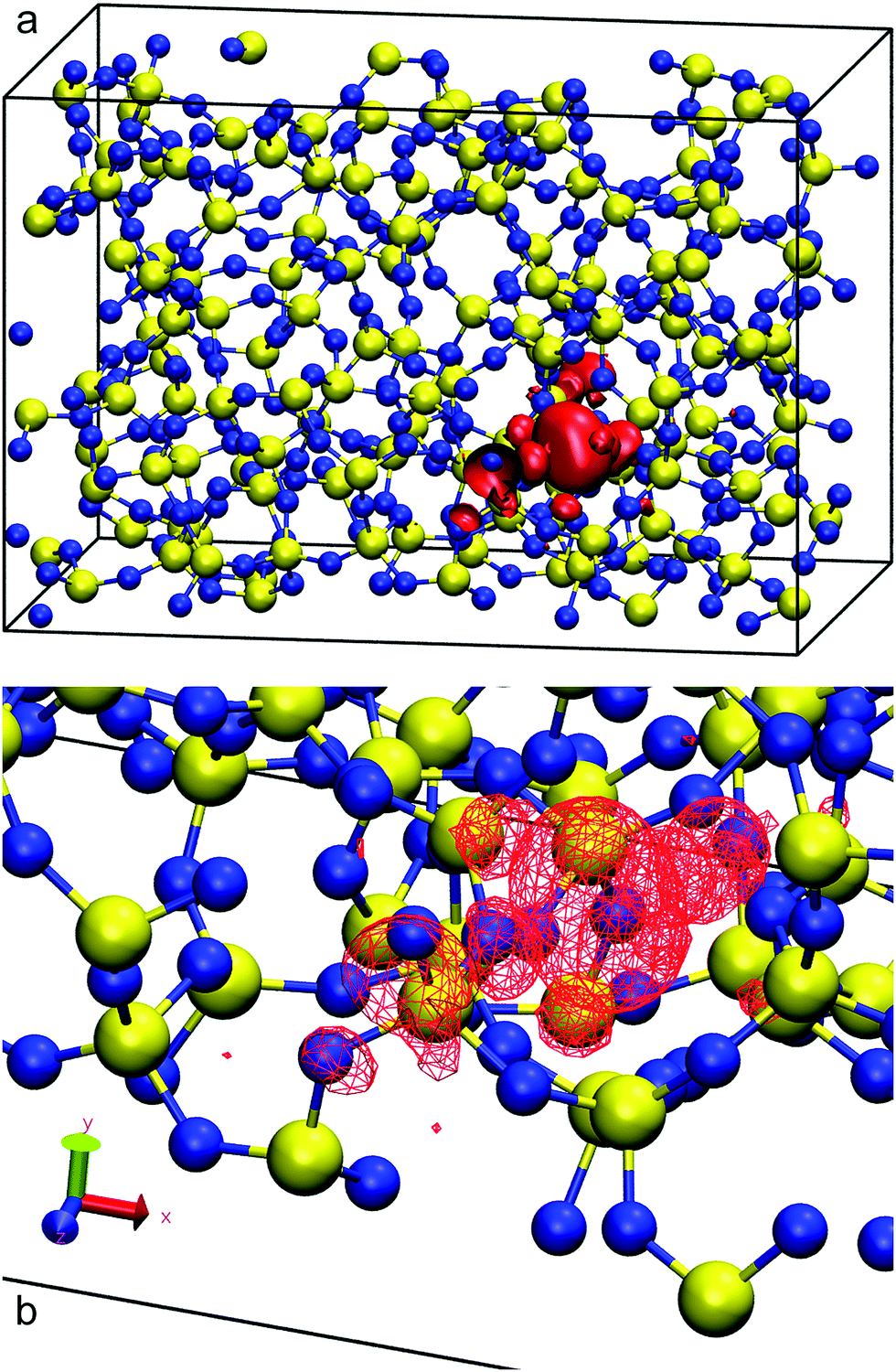 | ||
| Fig. 1 Red isosurfaces show electron charge densities of 14.05 × 10⁻⁴ electron per Bohr3 of the LUMO's 80% charge of amorphous silica, occupying a cavity between rings (a). Panel (b) shows a zoomed view of the cavity occupied by the LUMO. Silicon atoms are painted in yellow and oxygen in blue. | ||
| System | Calculation details | E LUMO E exp (eV) | E gap (eV) |
|---|---|---|---|
| Bulk a-SiO2 | 3D-periodic | −1.54 | 4.00 |
| Q4 surface SiO2 + 2.0 nm vacuum | 3D-periodic | −1.43 | 5.84 |
| Q4 surface SiO2 + 2.0 nm vacuum | 2D-slab | −2.06 | 5.75 |
| Q3Q4 surface SiO2 with [SiOH] = 1.61 nm−2 + 2.0 nm vacuum | 2D-slab | −1.65 | 6.36 |
| Q3Q4 surface SiO2 with [SiOH] = 3.22 nm−2 + 2.0 nm vacuum | 2D-slab | −1.33 | 6.20 |
| Q3Q4 surface SiO2 with [SiOH] = 4.84 nm−2 + 2.0 nm vacuum | 2D-slab | −1.49 | 5.97 |
| Q3Q4 surface SiO2 with [SiOH] = 6.86 nm−2 + 2.0 nm vacuum | 2D-slab | −1.25 | 5.99 |
| Bulk a-SiO2 | Experiment | −0.973 | 8.874 |
| Bulk water 150 molecules | 3D-periodic | — | 6.30 ± 0.19 |
| Slab of liquid water 150 molecules + 2.0 nm vacuum | 2D-slab | −0.12 ± 0.30 | 6.04 ± 0.39 |
| Slab of liquid water 200 molecules + 2.0 nm vacuum | 2D-slab | −0.03 ± 0.37 | 5.53 ± 0.59 |
| Bulk water | Experiment | −0.1275 | 6.974 |
| Bulk a-PE chains with ghost atoms separated by 0.148 nm | 3D-periodic with LDA in CP2k | −0.10 ± 0.37 | 7.66 ± 0.07 |
| Bulk a-PE rings with ghost atoms separated by 0.148 nm | 3D-periodic with LDA in CP2k | −0.14 ± 0.37 | 7.58 ± 0.07 |
| Bulk a-PE chains with ghost atoms separated by 0.148 nm | 3D-periodic with revised PBE in CP2k | 0.04 ± 0.38 | 7.72 ± 0.05 |
| Bulk a-PE rings with ghost atoms separated by 0.148 nm | 3D-periodic with revised PBE in CP2k | −0.14 ± 0.08 | 7.58 ± 0.07 |
| Bulk a-PE | Experiment | <0.076 | 8.877 |
Turning now to liquid water, Fig. 2 illustrates the distribution of 80% of the LUMO charge in the bulk phase with a 3D-periodic calculation and with vacuum in a 2D-slab simulation. In both cases, the electron with 80% of its charge is found between 0 and 25 ps in a region that encloses 46 molecules for the bulk and 42 molecules for the ensemble with a vapour (vacuum) interface. These two specific volumes are similar to those reported using a Lanczos algorithm, where the wavefunction overlapped around 37 water molecules within two 3D-periodic cubic simulation cells of 1.817 nm (200 molecules) and 2.464 nm (499 molecules).66 In the presence of a water interface, the excess electron sits at the interface as shown by the averaged profiles along the z-direction plotted in Fig. 3. Our simulations predict a diffusion coefficient for the excess electron of 1.16 × 10⁻⁹ m2 s−1 for the 3D-periodic system and an order of magnitude higher at 10.68 × 10⁻⁹ m2 s−1 for the 2D-slab with vacuum (see Fig. S2 and S3 in the ESI†), which compare reasonably well with the experimental measurement of 4.90 × 10⁻⁹ m2 s−1 at 298 K for bulk water.67
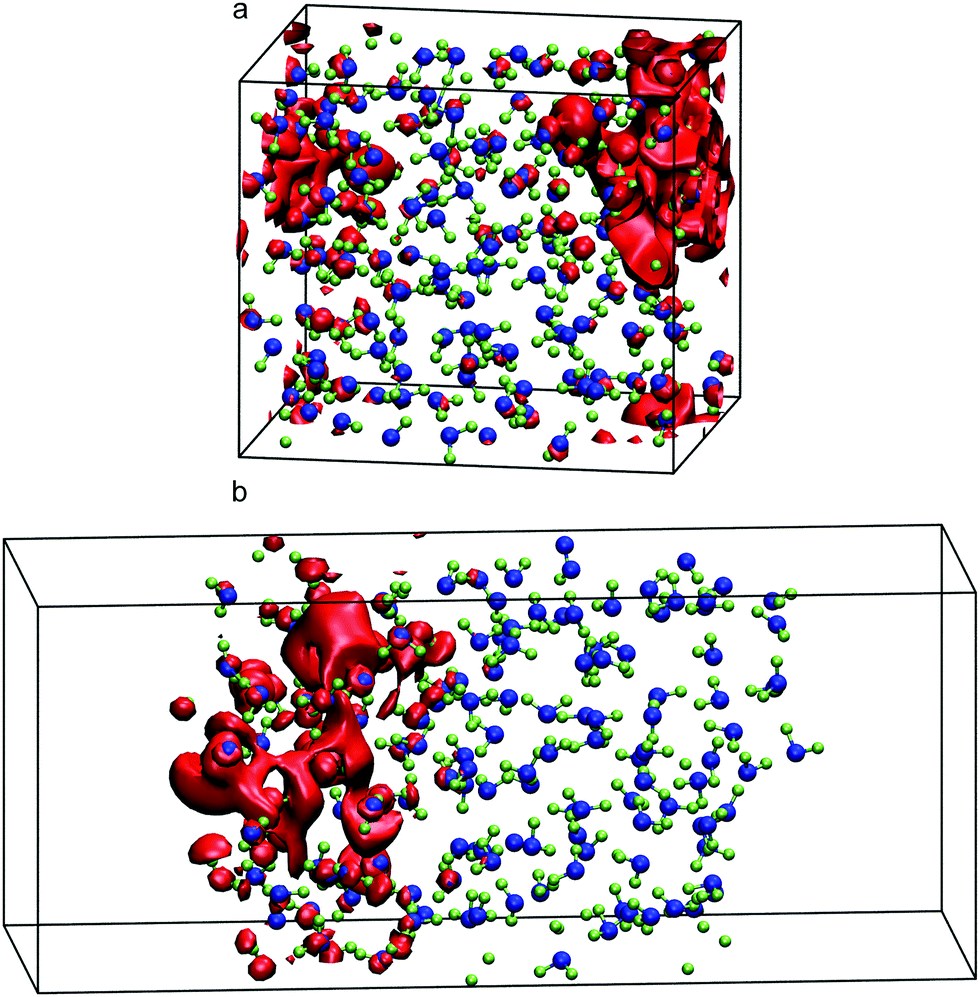 | ||
| Fig. 2 Red isosurfaces show 80% of the excess electron charge with values of 1.67 × 10⁻⁴ electron per Bohr3 in bulk (a) and 2.59 × 10⁻⁴ electron per Bohr3 with a 2.0 nm vacuum gap (b) of the LUMO of the neutral system of 150 molecules of bulk liquid water. Oxygen atoms are painted in blue and hydrogens in green. | ||
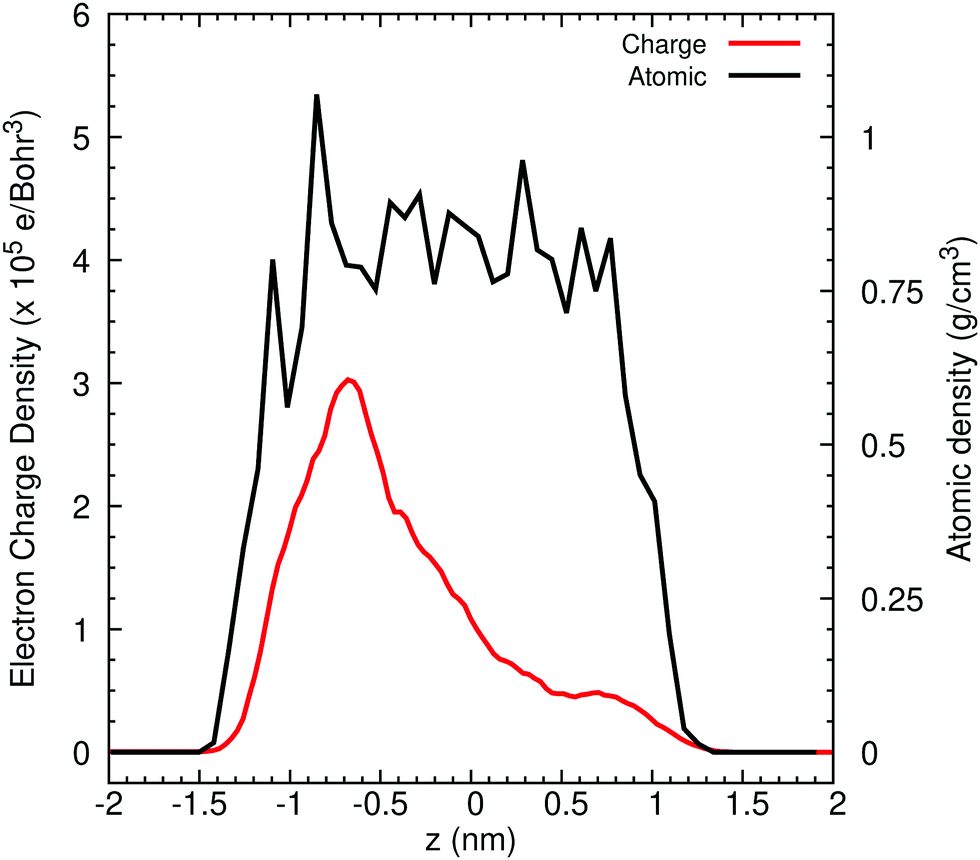 | ||
| Fig. 3 Averaged profiles of the LUMO charge and atomic densities across the z direction in a water/vacuum system with 150 molecules for different time intervals of ab initio molecular dynamics simulation. | ||
As previously discussed, the ground-state energy of the excess electron simulations is approximated as that of the LUMO(N). By averaging the energies of this orbital every 0.25 ps between 10.0 and 25.0 ps, we find an excess-electron energy of −0.12 (±0.30) eV in a 2D-slab simulation with its centre of charge located at z = −4.09 nm from the centre of mass of the 150-molecule system. With 200 molecules, this energy increases slightly to −0.03 (±0.37) eV but note the large standard deviation. Our predictions are in good agreement with those obtained with single-electron pseudopotential methods and experiments. For instance, Turi et al.68 found that the excess electron localises in cavities of bulk water with an average energy of −0.23 eV averaging over 500 configurations and 500 molecules. His predictions and ours compare well with experimental measurement of −0.12 eV (see Table 1). Note that, one advantage of using CRYSTAL17 with respect to pseudopotential methods, is that we can extract the energy of all electronic bands, including the HOMO. Doing so, we obtain an electronic band gap of 6.04 (±0.39) eV with 150 molecules and 5.53 (±0.59) eV with 200 molecules using 2D-slab water simulations, which underestimate the experiments by around 1.2 eV. This difference may arise from the presence of the interface or be reduced using more accurate techniques such as GW. Note relying strictly on a pure generalised gradient approximation (GGA) produces worse predictions.69 Of course, we can always tune the contribution of the Hartree–Fock exchange in B3LYP or other hybrid DFT functionals to obtain the experimental result.
III. 2. Interfaces of amorphous polyethylene and water
Taking as a reference the behaviour of excess electrons in pure water, we now analyse the interfacial system made by combining water with a slab of amorphous polyethylene. Unfortunately, in this case we cannot calculate the energy of the LUMO from a 2D-slab calculation with a system made of water, polyethylene, and vacuum as it requires running ab initio molecular dynamics with CP2k. This CP2k calculation requires in turn choosing an appropriate exchange–correlation functional and here we find that any PBE functional will ultimately cause the polymer chains to evaporate in the presence of vacuum. The alternative is to use LDA, which we find severely overestimates the density of water at 300 K. We therefore study interfacial systems of amorphous polyethylene and water with revPBE, but without a vacuum phase, thus preventing the disintegration of the polyethylene phase. Fig. 4 shows that in these systems the electron prefers to sit on a water region near the interface with polyethylene similar to the water/vacuum case. This result is consistent with the nature of polyethylene, a compound that repels injected negative charge carriers due to its negative electron affinity.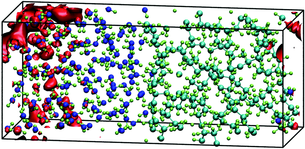 | ||
| Fig. 4 Red isosurfaces show an electron charge density of 1.65 × 10⁻⁴ electron per Bohr3 of the LUMO of the interfacial system of water and amorphous polyethylene at 15 ps of a 3D-periodic ab initio simulation that encloses 80% of the excess electron charge. | ||
Although we cannot provide LUMO energies, we believe that the impact of the polymer on the localisation and energy of the solvated electron should be small and therefore, we can assume that its energy can be taken from the 2D-slab calculations of water and vacuum. Furthermore, this two-component system offers us the possibility of studying the transport of the extra charge across the interfaces via calculating the valence (VBO) and conduction band (CBO) offsets. The former are determined using the method of layer-decomposed density of states proposed by Shi and Ramprasad70 since the traditional line-up method71 is more appropriate for crystalline systems as it assumes that the variation of the electrostatic potential is only affected by the changes of the outmost atomic layers assembled at the interface formed by two compounds. In contrast, in our work, the potential will also change due to the lack of periodic arrangement of the atomic positions in our amorphous and liquid systems. This aperiodicity obliges to us to apply the method of layer-decomposed density of states for a number of configurations (obtained every 0.25 ps) to obtain robust statistical results. In each configuration, we calculate the density of states with CRYSTAL17 in 15 slices of atoms with a thickness of 0.26 nm and from each slice spectrum we find the HOMO. We plot the HOMOs of each layer vs. its position perpendicular to the interface (e.g. z) and the valence band offset is taken as the maximum difference between the HOMOs in water and polyethylene (see Fig. S4 in the ESI†):
| VBO = max(EHOMO,a-PE − EHOMO,water), | (3) |
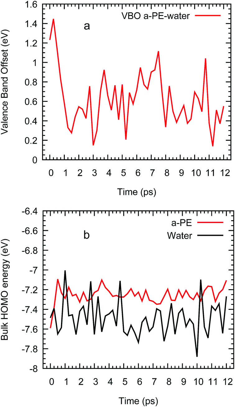 | ||
| Fig. 5 Valence band offset of an interfacial system of water and amorphous polyethylene vs. time (a) and HOMO of bulk water and polyethylene (b) from ab initio molecular simulations. | ||
Having determined the valence band offsets, we now calculate the conduction band offsets (CBO) which are defined as
| CBO = VBO + (Eg,a-PE − Eg,water) | (4) |
III. 3. Interfaces of amorphous polyethylene and silica
The isosurface at 80% of an excess electron charge represented by the LUMO from a 3D-periodic calculation with amorphous polyethylene and silica is illustrated for a Q4 surface in Fig. 6(a) and for a Q3/Q4 surface with a silanol concentration of 6.86 nm−2 in Fig. 6(b) after 7.5 of a CP2k run with PBEsol. These two isosurfaces show that the addition of OH groups on the surface makes the excess electron migrate to the inner layers of the silica, which is demonstrated quantitatively in the average charge profile drawn in Fig. 6(c) for all five silanol concentration. In contrast, when we impose a vacuum on both sides of the interfacial system, the excess electron sits at the silica/polyethylene interface for any finite silanol concentration, see the isosurfaces in Fig. 7(a) and (b) and the average charge profiles in Fig. 7(c) after 7.5 of a CP2k run with LDA to avoid polymer evaporation.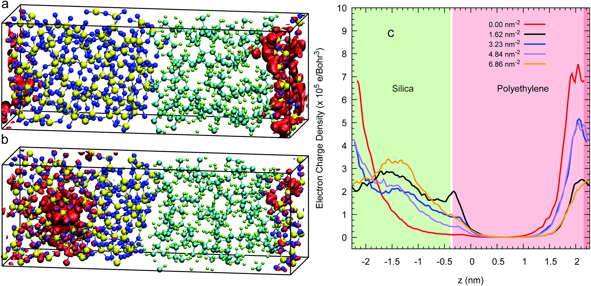 | ||
| Fig. 6 Panels (a) and (b) illustrate red isosurfaces with an electron charge density of 1.442 × 10⁻⁴ and 1.077 × 10⁻⁴ electron per Bohr3, respectively, of the 80% of the LUMO charge of the interfacial system of polyethylene (right) and amorphous silica (left) whose surfaces are Q4 (a) and Q3/Q4 with a silanol concentration of 6.86 nm2 (b) at 7.5 ps drawn from 3D simulations with no vacuum. Panel (c) plots the average longitudinal profile of the LUMO's charge density for a number of silanol concentrations. | ||
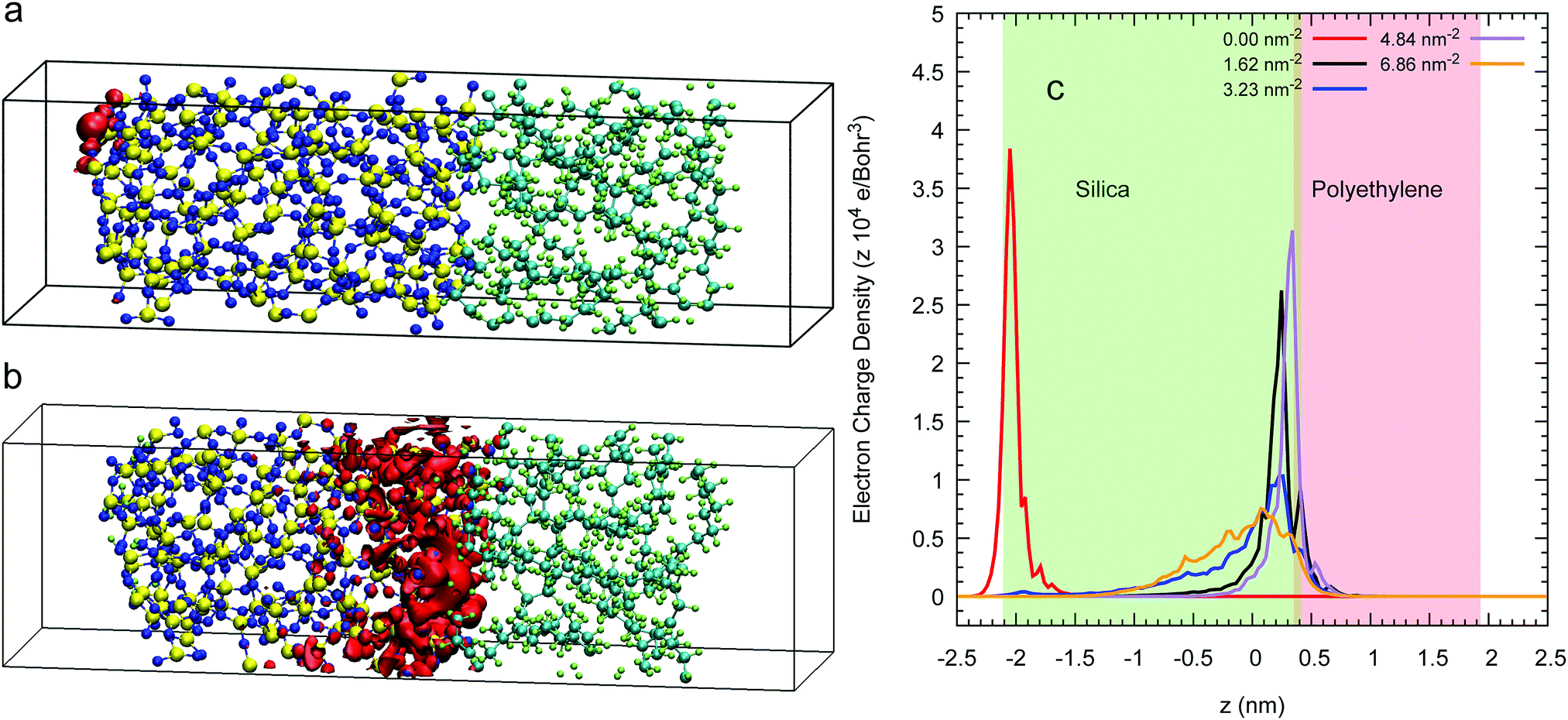 | ||
| Fig. 7 Panels (a) and (b) illustrate red isosurfaces with an electron charge density of 51.52 × 10⁻⁴ and 1.96 × 10⁻⁴ electron per Bohr3 of the 80% of the LUMO’ charge of the interfacial system of polyethylene (right) and amorphous silica (left) whose surfaces are Q4 (a) and Q3/Q4 with a silanol concentration of 6.86 nm2 (b) at 7.5 ps drawn from 2D SLAB simulations with vacuum. Panel (c) plots the average longitudinal profile of the LUMO's charge density for a number of silanol concentrations. Space not painted in colour represents vacuum. | ||
In addition, we also compare the valence band-offsets obtained from the 3D-periodic and 2D-slab Q4 calculations. We obtain 1.14 (±0.19) eV for the 3D-periodic case and 0.84 (±0.36) eV for the 2D-slab case. Using eqn (4) to calculate the CBO in this system by (experimental silica's band gap of 8.8 eV and the DFT amorphous polyethylene's of 8.01 eV) the CBOs will be 0.79 eV lower than the VBOs, at 0.33 eV for the 3D-periodic and 0.05 eV for the 2D-slab. The latter figure consistent with the dominant role of the interfaces in determining excess electron behaviour in the 2D slab.
For these 2D-slab cases, we plot in Fig. 8 the LUMO energies vs. silanol concentrations after correcting with respect to the vacuum level. Our results show that the energy of the excess electron increases with increasing concentration. We argue that this increase is caused by the increasing delocalisation of this orbital. The most negative energy is −1.75 eV with the Q4 surface, which is consistent with the value of −1.54 eV obtained when this slab is isolated with vacuum on both sides. When the silanol content increases, the LUMO position transits from the left interface to the right wall with some charge penetrating into the polyethylene. The hydroxylated silica/PE interfaces act as deep traps with energies between −1.75 eV and −0.99 eV (but see the next section for what happens if free water is present).
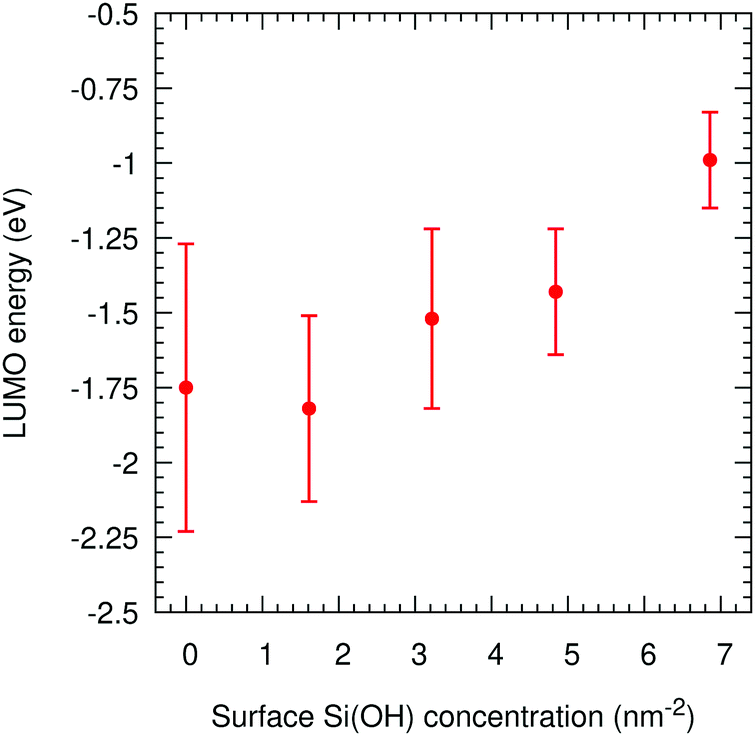 | ||
| Fig. 8 LUMO energies in amorphous polyethylene and silica vs. the silanol concentration on the surface for 2D-SLAB calculations. | ||
III. 4. Interfaces of amorphous silica and water
We now study excess electrons in systems made with an amorphous silica slab sandwiched with two ensembles of 150 water molecules on both sides as shown in Fig. 9 using the revPBE functional. These systems do not need to include polyethylene slabs which will repel the extra charge due to the negative electron affinity of this polymer. This behaviour is shown in water/polyethylene and silica/polyethylene interfaces, where the excess electron sits away from the polymer, which has little effect on its degree of localisation and energy. This water/silica/water system is run with CP2k and revPBE for 15 ps, during which the interfacial chemistry spontaneously produces four silanols on each silica wall equivalent to a silanol surface concentration of 1.62 nm−2. This concentration is slightly higher than the 1.37 nm−2 reported on nanoporous silica surfaces modelled with an NVT molecular dynamics for 30 ps using CP2k and the BLYP functional.72 However, both values underestimate the experimental range between 4.2 and 5.7 nm−2 collected in ref. 53 for a range of different treatments to rehydroxylate silica surfaces. This disagreement is expected given the different length and time scales in simulations and experiments.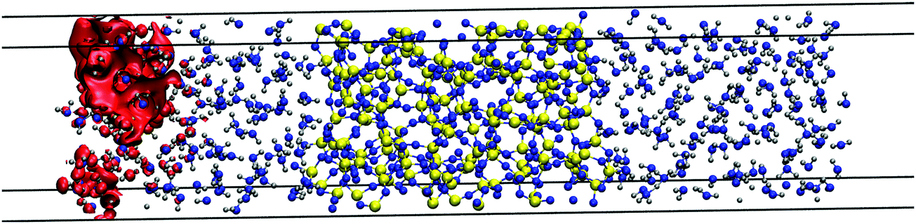 | ||
| Fig. 9 Red isosurface of 2.42 × 10⁻⁴ electron per Bohr3 shows the position of the 80% of the LUMO's charge at 10 ps of a system made with amorphous silica and two systems of 150 water molecules. | ||
Once the system is well stabilised after 7 ps, the spatial localisation of the excess electron shows a very similar picture as in the water/vacuum case given that this particle again sits near the vacuum on the left liquid ensemble as shown at several CP2k simulation times in Fig. 10(a). Moreover, this same behaviour is also seen in the LUMO energies of this system in Fig. 10(b), which show an increase as water density slightly decreases and silanol groups are formed on both surfaces with an average value of −0.27 (±0.53) eV between 4 and 15 ps. With a standard deviation nearly two times higher than the absolute value of the average, our DFT methodology predicts that the excess electron in this system oscillates around the same average energy as in the case of a vacuum/water systems, leading us to conclude that, in the presence of water, the detailed interfacial chemistry of the silica surface does not influence the behaviour of the excess electron in nanocomposite materials.
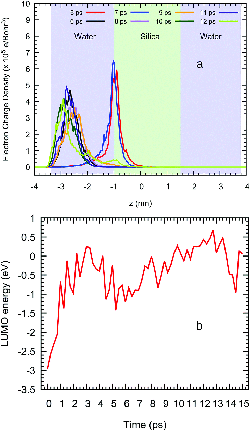 | ||
| Fig. 10 (a) Average profile of the LUMO charge density across the z direction and (b) the energy of this orbital vs. the ab initio simulation time in a water/silica/water system. | ||
IV. Conclusion
We have calculated the energy and degree of localisation of excess electrons at a number of interfaces made by combining amorphous polyethylene, silica, and liquid water to be representative of interfaces to be found in wet and dry polymer nanocomposites. For pure silica we find an excess electron would be strongly localised with an energy of around −1.5 eV. Hydroxylating the silica surface and adding a polyethylene interface produces a strong dependence of the excess electron behaviour on the silanol concentration. An excess electron sits at the interface with an energy of between −1.75 eV for the Q4 surface chemistry and −0.99 eV for the Q3/Q4, becoming less localised with increasing silanol density. However, in the presence of a water film, the detailed interfacial chemistry of the silica surface becomes irrelevant and the excess electron sits preferentially at the water/vapour interface with an energy of minus a few tenths of an eV. We conclude that the moisture content of a polymer nanocomposite has a profound influence on the electron trapping behaviour with a wet interfacial material producing much lower trapping energies and a high excess electron mobility (from the Einstein relation). We would then expect that a wet nanocomposite with a percolating water film would show increased electrical conductivity, independent of surface chemistry, which is consistent with our experimental data for low density polyethylene octylnanosilica composites.32Conflicts of interest
There are no conflicts to declare.Acknowledgements
The authors acknowledge the financial support of EPSRC through grant EP/N002288/1, Advanced Polymer Material for Energy Security – POLYMAT and HPC support through ARCHER project e446. This work was supported by EPSRC through a Service Level Agreement with STFC Scientific Computing Department and by the UK Materials Chemistry Consortium (Grant EP/L000202). NQ thanks Alun Vaughan for useful discussions.References
- C. J. Lombardo, M. S. Glaz, Z.-E. Ooi, D. A. Vanden Bout and A. Dodabalapur, Phys. Chem. Chem. Phys., 2012, 14, 13199–13203 RSC.
- C. Groves, J. C. Blakesley and N. C. Greenham, Nano Lett., 2010, 10, 1063–1069 CrossRef CAS PubMed.
- L. G. Kaake, P. F. Barbara and X. Y. Zhu, J. Phys. Chem. Lett., 2010, 1, 628–635 CrossRef CAS.
- M. A. Henderson, J. M. White, H. Uetsuka and H. Onishi, J. Am. Chem. Soc., 2003, 125, 14974–14975 CrossRef CAS PubMed.
- Y. Okahata, T. Kobayashi, K. Tanaka and M. Shimomura, J. Am. Chem. Soc., 1998, 120, 6165–6166 CrossRef CAS.
- R. Rinaldi, E. Branca, R. Cingolani, R. Di Felice, A. Calzolari, E. Molinari, S. Masiero, G. Spada, G. Gottarelli and A. Garbesi, Ann. N. Y. Acad. Sci., 2002, 960, 184–192 CrossRef CAS PubMed.
- P. F. Barbara, T. J. Meyer and M. A. Ratner, J. Phys. Chem., 1996, 100, 13148–13168 CrossRef CAS.
- B. L. Mahaney and K. Meek, J. Biochem., 2009, 417, 639–650 CrossRef CAS PubMed.
- Z. G. Yu and X. Song, Phys. Rev. Lett., 2001, 86, 6018–6021 CrossRef CAS PubMed.
- Around 9% of the generated electricity is lost through transmission and distribution, amounting to an estimated financial loss of 3 trillion U.S. dollars a year worldwide according to the International Electrotechnical Commission: http://www.iec.ch/, accessed February 2018.
- B. Chu, X. Zhou, K. Ren, B. Neese, M. Lin, Q. Wang, F. Bauer and Q. M. Zhang, Science, 2006, 313, 334–336 CrossRef CAS PubMed.
- V. Sharma, C. Wang, R. G. Lorenzini, R. Ma, Q. Zhu, D. W. Sinkovits, G. Pilania, A. R. Oganov, S. Kumar, G. A. Sotzing, S. A. Boggs and R. Ramprasad, Nat. Commun., 2014, 5, 4845 CrossRef CAS PubMed.
- T. D. Huan, S. Boggs, G. Teyssedre, C. Laurent, M. Cakmak, S. Kumar and R. Ramprasad, Prog. Mater. Sci., 2016, 83, 236–239 CrossRef CAS.
- M. H. Yoon, H. Yan, A. Facchetti and T. J. Marks, J. Am. Chem. Soc., 2005, 127, 10388–10395 CrossRef CAS PubMed.
- M. E. Roberts, N. Queraltó, S. C. B. Mannsfeld, B. N. Reinecke, W. Knoll and Z. Bao, Chem. Mater., 2009, 21, 2292–2299 CrossRef CAS.
- M. A. Hickner, H. Ghassemi, Y. S. Kim, B. R. Einsla and J. E. McGrath, Chem. Rev., 2004, 104, 4587–4612 CrossRef CAS PubMed.
- Y. J. Wang, J. Qiao, R. Baker and J. Zhang, Chem. Soc. Rev., 2013, 42, 5768–5787 RSC.
- S. Dadbin, M. Frounchi, M. H. Saeid and F. Gangi, J. Appl. Polym. Sci., 2002, 86, 1959–1969 CrossRef CAS.
- L. A. Dissado and J. C. Fothergill, Electrical Degradation and Breakdown in Polymers, P. Peregrinus, London, 1992 Search PubMed.
- W. L. Hawkins, Polymer Degradation and Stabilization, Springer-Verlag, Berlin, 1984 Search PubMed.
- See review on silicate nanocomposites by S. S. Ray and M. Okamoto, Prog. Polym. Sci., 2003, 28, 1539–1641 CrossRef CAS.
- See review by Y. Tanaka, N. Ohnuma, K. Katsunami and Y. Ohki, IEEE Trans. Electr. Insul., 1991, 26, 258–265 CrossRef CAS.
- Y. Rao and C. P. Wong, J. Appl. Polym. Sci., 2004, 92, 2228–2231 CrossRef CAS.
- R. C. Smith, C. Liang, M. Landry, J. K. Nelson and L. S. Schadler, IEEE Trans. Dielectr. Electr. Insul., 2008, 15, 187–196 CAS.
- Y. Wang, D. MacKernan, D. Cubero, D. Coker and N. Quirke, J. Chem. Phys., 2014, 140, 154902 CrossRef.
- M. Meunier, A. Aslanides and N. Quirke, J. Chem. Phys., 2001, 115, 2876–2881 CrossRef CAS.
- X. Huang, P. Jiang and Y. Yin, Appl. Phys. Lett., 2009, 95, 242905 CrossRef.
- C. M. Osburn and D. W. Ormond, J. Electrochem. Soc., 1972, 119, 591–597 CrossRef CAS.
- V. V. Afanas'ev and A. Stesmans, Phys. Rev. Lett., 1997, 78, 2437 CrossRef.
- Defects in Microelectronic Materials and Devices, ed. D. M. Fleetwood, S. T. Pantelides and R. D. Schrimpf, CRC Press, Boca Raton, 2009 Search PubMed.
- T. Y. Chan, K. K. Young and C. Hu, IEEE Electron Device Lett., 1987, 8, 93–95 Search PubMed.
- S. Virtanen, A. S. Vaughan, L. Yang, F. Saiz and N. Quirke, Dielectric Breakdown Strength and Electrical Conductivity of Low Density Polyethylene Octylnanosilica Composite, IEEE Conference on Electrical Insulation and Dielectric Phenomena (IEEE CEIDP), IEEE, pp. 58-61, ISSN: 0084-9162, 2016, see also S. Virtanen, A. S. Vaughan, L. Yang, F. Saiz and N. Quirke, Electrical Conductivity and Moisture Uptake Studies of Low Density Polyethylene Octyl-nanosilica Composite, conference paper, 25th Nordic Insulation Symposium on Materials, Components and Diagnostics, 2017.
- M. Meunier and N. Quirke, J. Chem. Phys., 2000, 113, 369–376 CrossRef CAS.
- D. Cubero, N. Quirke and D. F. Coker, J. Chem. Phys., 2003, 119, 2669–2679 CrossRef CAS.
- D. Cubero and N. Quirke, J. Chem. Phys., 2004, 120, 7772–7778 CrossRef CAS PubMed.
- M. C. Righi, S. Scandolo, S. Serra, S. Iarlori, E. Tosatti and G. Santoro, Phys. Rev. Lett., 2001, 87, 076802 CrossRef CAS PubMed.
- M. Unge, T. Christen and C. Törnkvist, Electronic structure of polyethylene—Crystalline and amorphous phases of pure polyethylene and their interfaces, Annual Report Conference on Electrical Insulation and Dielectric Phenomena (CEIDP), IEEE, 2012, pp. 525–530 Search PubMed.
- S. Serra, S. Iarlori, E. Tosatti, S. Scandolo, M. C. Righi and G. E. Santoro, Chem. Phys. Lett., 2002, 360, 487–493 CrossRef CAS.
- M. Unge and T. Christen, Chem. Phys. Lett., 2014, 613, 15–18 CrossRef CAS.
- R. Stowasser and R. Hoffmann, J. Am. Chem. Soc., 1999, 121, 3414–3420 CrossRef CAS.
- F. Saiz, D. Cubero and N. Quirke, Phys. Chem. Chem. Phys., 2018 10.1039/C8CP01330F.
- L. T. Zhuravlev, Colloids Surf., A, 2000, 173, 1–38 CrossRef CAS.
- M. Schneemilch and N. Quirke, J. Chem. Phys., 2018, 148, 194704 CrossRef CAS PubMed.
- S. J. Plimpton, J. Comput. Phys., 1995, 117, 1–19 CrossRef CAS.
- R. J. Hemley, A. P. Jephcoat, H. K. Mao, L. C. Mingt and M. H. Manghnanit, Nature, 1988, 334, 52–54 CrossRef CAS.
- Dassault Systèmes BIOVIA, Materials Studio Suite, v.5.5.2, San Diego, Dassault Systèmes, 2017 Search PubMed.
- H. Sun, J. Phys. Chem. B, 1998, 102, 7338–7364 CrossRef CAS.
- J. Hutter, M. Iannuzzi, F. Schiffmann and J. VandeVondele, Comput. Mol. Sci., 2014, 4, 15–25 CrossRef CAS.
- J. VandeVondele, M. Krack, F. Mohamed, M. Parrinello, T. Chassaing and J. Hutter, Comput. Phys. Commun., 2005, 167, 103–128 CrossRef CAS.
- S. Goedecker, M. Teter and J. Hutter, Phys. Rev. B: Condens. Matter Mater. Phys., 1996, 54, 1703 CrossRef CAS.
- M. Krack, Theor. Chem. Acc., 2005, 114, 145–152 Search PubMed.
- S. Grimme, J. Comput. Chem., 2006, 27, 1787–1799 CrossRef CAS PubMed.
- T. P. M. Goumans, A. Wander, W. A. Brown and C. R. A. Catlow, Phys. Chem. Chem. Phys., 2007, 9, 2146–2152 RSC.
- L. T. Zhuralev, Langmuir, 1987, 3, 316–318 CrossRef.
- M. Dion, H. Rydberg, E. Schröder, D. C. Langreth and B. I. Lundqvist, Phys. Rev. Lett., 2005, 92, 246401 CrossRef PubMed.
- J. L. Abascal and C. Vega, J. Chem. Phys., 2005, 123, 234505 CrossRef CAS PubMed.
- J. P. Perdew, K. Burke and M. Ernzerhof, Phys. Rev. Lett., 1986, 77, 3865–3868 CrossRef PubMed.
- B. Hammer, L. B. Hansen and J. K. Nørskov, Phys. Rev. B: Condens. Matter Mater. Phys., 1999, 59, 7413 CrossRef.
- J. P. Perdew, A. Ruzsinszky, G. I. Csonka, O. A. Vydrov, G. E. Scuseria, L. A. Constantin, X. Zhou and K. Burke, Phys. Rev. Lett., 2008, 100, 136406 CrossRef PubMed.
- R. Dovesi, R. Orlando, A. Erba, C. M. Zicovich-Wilson, B. Civalleri, S. Casassa, L. Maschio, M. Ferrabone, M. De La Pierre, P. D’Arco, Y. Noel, M. Causa, M. Rerat and B. Kirtman, Int. J. Quantum Chem., 2014, 114, 1287–1317 CrossRef CAS.
- G. A. Petersson, A. Bennett, T. G. Tensfeldt, M. A. Al-Laham, W. A. Shirley and J. Mantzaris, J. Chem. Phys., 1988, 89, 2193–2218 CrossRef CAS.
- G. A. Petersson and M. A. Al-Laham, J. Chem. Phys., 1991, 94, 6081–6090 CrossRef CAS.
- E. G. Lewards, Computational Chemistry, Springer, New York, 2nd edn, 2011, ch. 5, pp. 232–255 Search PubMed.
- Al-M. El-Sayed, M. B. Watkins, V. V. Afanas’ev and A. L. Shluger, Phys. Rev. B: Condens. Matter Mater. Phys., 2014, 89, 125201 CrossRef.
- M. Chiesa, M. C. Paganini and E. Giamello, Chem. Phys. Chem., 2004, 5, 1897–1900 CrossRef CAS PubMed.
- R. E. Larsen, W. J. Glover and B. J. Schwartz, Science, 2010, 329, 65–69 CrossRef CAS PubMed.
- K. H. Schmidt, P. Han and D. M. Bartels, J. Phys. Chem., 1992, 96, 199–206 CrossRef CAS.
- L. Turi, Á. Madarász and P. J. Rossky, J. Chem. Phys., 2006, 125, 014308 CrossRef PubMed.
- M. Chen, H.-Y. Ko, R. C. Remsing, M. F. Calegari Andrade, B. Santra, Z. Sun, A. Selloni, R. Car, M. L. Klein, J. P. Perdew and X. Wu, Proc. Natl. Acad. Sci. U. S. A., 2017, 114, 10846–10851 CrossRef CAS PubMed.
- N. Shi and R. Ramprasad, IEEE Trans. Dielectr. Electr. Insul., 2008, 15, 170–177 CAS.
- C. G. Van de Walle and R. M. Martin, Phys. Rev. B: Condens. Matter Mater. Phys., 1987, 35, 8154–8165 CrossRef CAS.
- J. M. Rimsza, J. Yeon, A. C. T. van Duin and J. Du, J. Phys. Chem. C, 2016, 120, 24803–24816 CrossRef CAS.
- Taken as the electron affinity from the photoemission experiments made by V. W. Ballarotto, M. Breban, K. Siegrist, R. J. Phaneuf and E. D. Williams, J. Vac. Sci. Technol., B, 2002, 20, 2514–2518 CrossRef CAS on devices covered by ultrathin SiO2 layers.
- S. W. King, J. Brockman, M. French, M. Jaehnig, M. Kuhn and B. French, J. Appl. Phys., 2014, 116, 113703 CrossRef.
- J. V. Coe, A. D. Earhart, M. C. Cohen, G. J. Hoffman, H. W. Sarkas and K. H. Bowen, J. Chem. Phys., 1997, 107, 6023–6031 CrossRef CAS . See also J. V. Coe, Int. Rev. Phys. Chem., 2001, 20, 33–58 Search PubMed . This value of 6.9 eV is in good agreement by 7.3 eV obtained with start-of-the-art GW calculations by C. Fang, W.-F. Li, R. S. Koster, J. Klimeš, A. van Blaaderen and M. A. van Huis, Phys. Chem. Chem. Phys., 2015, 17, 365–375 RSC.
- K. J. Less and E. G. Wilson, J. Phys. C: Solid State Phys., 1973, 6, 3110–3120 CrossRef CAS.
- Measured value for the alkane C36H74 of 8.8 eV by E. Cartier and P. Pfluger, Phys. Rev. B: Condens. Matter Mater. Phys., 1986, 34, 8822–8827 CrossRef CAS.
Footnote |
| † Electronic supplementary information (ESI) available. See DOI: 10.1039/c8cp04741c |
| This journal is © the Owner Societies 2018 |