
 Open Access Article
 This Open Access Article is licensed under a
 Creative Commons Attribution 3.0 Unported Licence
CO2 interaction with violarite (FeNi2S4) surfaces: a dispersion-corrected DFT study†
Sergio
Posada-Pérez
 a,
David
Santos-Carballal
b,
Umberto
Terranova
b,
Alberto
Roldan
b,
Francesc
Illas
a and
Nora H.
de Leeuw
*bc
a,
David
Santos-Carballal
b,
Umberto
Terranova
b,
Alberto
Roldan
b,
Francesc
Illas
a and
Nora H.
de Leeuw
*bc
aDepartament de Ciència de Materials i Química Física & Institut de Química Teòrica i Computacional (IQTCUB), Universitat de Barcelona, c/ Martí i Franquès 1, 08028 Barcelona, Spain
bSchool of Chemistry, Cardiff University, Main Building, Park Place, Cardiff CF10 3AT, UK. E-mail: deLeeuwN@cardiff.ac.uk; Tel: +44 (0)29 2087 0219
cDepartment of Earth Sciences, Utrecht University, Princetonplein 8A, 3584 CD Utrecht, The Netherlands
First published on 16th July 2018
Abstract
The unbridled emissions of gases derived from the use of fossil fuels have led to an excessive concentration of carbon dioxide (CO2) in the atmosphere with concomitant problems to the environment. It is therefore imperative that new cost-effective catalysts are developed to mitigate the resulting harmful effects through the activation and conversion of CO2 molecules. In this paper, we have used calculations based on the density functional theory (DFT), including two semi-empirical approaches for the long-range dispersion interactions (-D2 and -D3), to explore the interaction of CO2 with the surfaces of spinel-structured violarite (FeNi2S4). This ternary sulfide contains iron ions in the highest possible oxidation state, while the nickel atoms are in the mixed 2+/3+ valence state. We found that CO2 interaction with violarite is only moderate due to the repulsion between the oxygen lone pairs and the electronic clouds of the sulfur surface atoms. This suggests that the CO2 activation is not dictated by the presence of nickel, as compared to the pure iron-isomorph greigite (Fe3S4). These results differ from findings in (Ni,Fe) ferredoxin enzymes, where the Ni/Fe ratio influences the redox potential, which suggests that the periodic crystal structure of violarite may hinder its redox capability.
1. Introduction
The unbridled anthropogenic emissions of carbon dioxide (CO2) into the Earth's atmosphere from burning fossil fuels have caused a rise in the average global temperature, owing mostly to the greenhouse effect.1 Current estimates suggest that CO2 emissions will continue to increase until 2040, in line with the global energy demands,2 with potentially irreversible consequences to life on Earth. For this reason, many efforts have been dedicated to capture and utilise CO2 as a chemical feedstock to produce platform chemicals.3Commonly, the limiting rate during CO2 conversion is the activation of the C![[double bond, length as m-dash]](https://www.rsc.org/images/entities/char_e001.gif) O bond, which typically implies the bending of the molecule, a process often induced by occupation of the lowest unoccupied molecular orbital (LUMO) of the neutral molecule, thus displaying a clear antibonding character.4 This is, however, a challenging process because CO2 is extremely stable and most often interacts only weakly with many surfaces. Activation may be achieved by adding promoters to an otherwise inactive surface5 or by making use of more reactive catalytic materials. In this respect, a significant number of studies have been reported in the literature on the CO2 adsorption, activation, and conversion on metals,6,7 metal-oxides,8,9 and metal organic frameworks.10,11 Recently, it has been shown that molybdenum carbide surfaces strongly activate this very stable molecule.12,13 In the current search for new catalysts, transition metal sulfides have gained attention as a promising alternative, due to their high abundance, low cost, and prominent catalytic features. For example, iron sulfides have been suggested as catalysts for the activation and conversion of CO2,14,15 thereby also supporting the iron–sulfur hypothesis for the origin of life by Wächtershäuser and co-workers, which proposes that many of the prebiotic chemical reactions may have been catalysed by (Ni,Fe) sulfide minerals.16,17 Previous studies have revealed that Ni is vital to modulate an adequate redox potential in (Ni,Fe) complexes, e.g. ferredoxin enzymes, and therefore to control their (bio-)catalytic activity.18,19 However, the catalytic properties of the (Ni,Fe) sulfide environment within a periodic crystal structure, and thus whether Ni may enhance or hinder the redox capability in (Ni,Fe) sulfides compared to the pure iron sulfides, are not yet fully understood.
O bond, which typically implies the bending of the molecule, a process often induced by occupation of the lowest unoccupied molecular orbital (LUMO) of the neutral molecule, thus displaying a clear antibonding character.4 This is, however, a challenging process because CO2 is extremely stable and most often interacts only weakly with many surfaces. Activation may be achieved by adding promoters to an otherwise inactive surface5 or by making use of more reactive catalytic materials. In this respect, a significant number of studies have been reported in the literature on the CO2 adsorption, activation, and conversion on metals,6,7 metal-oxides,8,9 and metal organic frameworks.10,11 Recently, it has been shown that molybdenum carbide surfaces strongly activate this very stable molecule.12,13 In the current search for new catalysts, transition metal sulfides have gained attention as a promising alternative, due to their high abundance, low cost, and prominent catalytic features. For example, iron sulfides have been suggested as catalysts for the activation and conversion of CO2,14,15 thereby also supporting the iron–sulfur hypothesis for the origin of life by Wächtershäuser and co-workers, which proposes that many of the prebiotic chemical reactions may have been catalysed by (Ni,Fe) sulfide minerals.16,17 Previous studies have revealed that Ni is vital to modulate an adequate redox potential in (Ni,Fe) complexes, e.g. ferredoxin enzymes, and therefore to control their (bio-)catalytic activity.18,19 However, the catalytic properties of the (Ni,Fe) sulfide environment within a periodic crystal structure, and thus whether Ni may enhance or hinder the redox capability in (Ni,Fe) sulfides compared to the pure iron sulfides, are not yet fully understood.
In this work, we have focused on determining whether the CO2 molecule is activated upon interaction with this FeNi2S4 thiospinel and the role of the Ni atom on the catalytic properties by comparison with other pure iron sulfide phases. We have employed calculations based on the density functional theory (DFT) and periodic slab models to study the CO2 interaction with several different {001} and {111} low Miller index surface terminations of the stoichiometric ternary thiospinel violarite (FeNi2S4).20 In particular, we have explored the performance of a number of exchange correlation functionals and dispersion correction approximations, before comparing and rationalising our results with previous reports on greigite (Fe3S4), and magnetite (Fe3O4).9,15
2. Computational details
The periodic DFT-based calculations described in the present work have been carried out using the Vienna ab initio simulation package (VASP).21 The valence electron density was expanded in a plane-wave basis set and the effect of the core electrons (up to and including the 3p for Fe and Ni, 2p for S and 1s for C and O) on the valence region was described by the projector augmented wave (PAW) method by Blöchl,22 as implemented by Kresse and Joubert.23 The kinetic energy cut-off for the plane-wave basis set was truncated at 600 eV leading to negligible Pulay stress. The threshold for the convergence of the electronic optimization was 10−5 eV, while the relaxation of the atomic positions was allowed until the forces acting on all the atoms were smaller than 0.01 eV Å−1. Γ-Centred Monkhorst–Pack grids of 5 × 5 × 5 and 5 × 5 × 1 k-points in the reciprocal space were used for the simulation of the bulk and surface slabs, respectively.24 A single Γ-centred k-point was used for the simulation of the isolated CO2 molecule in a broken symmetry cell of 9 Å × 10 Å × 11 Å to avoid spurious interactions.For each of our simulations, we have optimised the geometries and evaluated the energies at two different levels of the generalized gradient approximation (GGA), i.e. using the Perdew–Wang 91 (PW91)25,26 and the Perdew–Burke–Ernzerhof (PBE)27,28 exchange–correlation functionals and taking into account spin polarization. The PW91 calculations were corrected with the spin interpolation formula of Vosko et al.29 To remain consistent with previous reports,9,14,15 long-range dispersion interactions were added to all the simulations via the D230 and the zero-damping D3 (zero)31 semi-empirical methods. Note that different vdW schemes show the same trends albeit with some differences in the absolute values.32 The global scaling parameter of s6 = 0.75 developed for the D2 correction of the PBE functional was also used for the PW91 calculations, in line with previous studies.9,14,33
The DFT+U formalism was used following the method suggested by Dudarev34,35 to better describe the local character of the strongly correlated 3d electrons of the Fe and Ni atoms. Following earlier works, a Ueff value of 1.0 eV was applied to the Fe 3d states when using the PW91 functional.33 For the calculations with the PBE functional, we have chosen larger Ueff values for 3.5 eV and 4.5 eV for the Fe and Ni 3d orbitals, which had been found to be required for the closely related PBEsol functional.36 The atomic charges and spin moments were analysed using the Bader Atoms in Molecules formalism37 according to the implementation by Henkelman et al.38,39 which is compatible with VASP. For each surface, the most favourable adsorption mode has been analysed further by means of the charge density difference (CDD). The CDD plots have been obtained following eqn (1),
| ρ = ρA–B − ρA − ρB | (1) |
3. Results and discussion
3.1. Bulk model
FeNi2S4 has a face-centred cubic (fcc) crystal structure with space group Fd![[3 with combining macron]](https://www.rsc.org/images/entities/char_0033_0304.gif) m (No. 227). The conventional cubic unit cell contains eight formula units of FeNi2S4, where the 32 sulfur anions form an approximately close-packed arrangement along the [111] direction, with 8 metal atoms located on the tetrahedral “A” positions (Wyckoff 8a sites) and 16 on the octahedral “B” positions (Wyckoff 16d sites). In the so-called normal violarite mineral, the Fe atoms occupy the tetrahedral positions while the Ni ions are filling the octahedral holes. In the inverse thiospinel, half of the Ni cations occupy the tetrahedral sites, with the other Ni cations and the Fe atoms located in the octahedral positions. Theoretical works based on DFT and Monte-Carlo simulations, where Ueff = 1.0 eV was applied to Fe, have revealed a completely inverse distribution of cations,33 in agreement with powder diffraction measurements between 100 and 573 K,40 Mössbauer data41 and extended X-ray absorption42 studies. However, a more recent computational study, where both Fe and Ni d orbitals were corrected with a Hubbard Hamiltonian by 3.5 and 4.5 eV, respectively, has shown that normal violarite is energetically more stable than the inverse form by 0.40 eV.43 Santos-Carballal et al.43 hypothesised that the synthesis of violarite produces the inverse spinel as a kinetic product, whilst its formation in the ores deep below the Earth's surface leads to the thermodynamic product with the normal distribution of cations. Calculations for the bulk phases have been carried out using the conventional cubic unit cell with an inverse spinel structure, see Fig. 1. Optimized lattice parameters of 9.402, 9.635, 9.713 and 9.709 Å have been predicted by the PW91-D2+U, PBE-D2+U, PBE-D3+U and PBE+U functionals respectively. These results compare well with the experimental value of 9.465 Å and show that, whereas changing from PW91 to PBE introduces a noticeable difference, the effect of the dispersion correction is minimal. The difference between PW91 and PBE is quite surprising and at variance with reported behaviour in other systems, e.g. the full set of transition metals.44 Inverse violarite is a ferrimagnetic thiospinel with metallic character, where the magnetic moments of the atoms filling the tetrahedral positions are aligned antiparallel to the spin moments of the ions occupying the octahedral sites,45,46 leading to a magnetisation of saturation of ∼4.00 μB per formula unit.43 Disappointingly, the PW91+U functional is unable to describe the appropriate spinel magnetic configuration. Note that, regardless of the methodology used, we have set the initial magnetic moments parallel within each sublattice and antiparallel to the other sublattice. They were allowed to relax during our simulations. However, the calculations with the PBE+U functional predict the correct magnetic order, as shown in Table 1. In view of the close similarity of the PW91 and PBE functionals, we attribute the different descriptions of the two exchange–correlation approximations to the different Ueff value used for the Fe and Ni 3d electrons.
m (No. 227). The conventional cubic unit cell contains eight formula units of FeNi2S4, where the 32 sulfur anions form an approximately close-packed arrangement along the [111] direction, with 8 metal atoms located on the tetrahedral “A” positions (Wyckoff 8a sites) and 16 on the octahedral “B” positions (Wyckoff 16d sites). In the so-called normal violarite mineral, the Fe atoms occupy the tetrahedral positions while the Ni ions are filling the octahedral holes. In the inverse thiospinel, half of the Ni cations occupy the tetrahedral sites, with the other Ni cations and the Fe atoms located in the octahedral positions. Theoretical works based on DFT and Monte-Carlo simulations, where Ueff = 1.0 eV was applied to Fe, have revealed a completely inverse distribution of cations,33 in agreement with powder diffraction measurements between 100 and 573 K,40 Mössbauer data41 and extended X-ray absorption42 studies. However, a more recent computational study, where both Fe and Ni d orbitals were corrected with a Hubbard Hamiltonian by 3.5 and 4.5 eV, respectively, has shown that normal violarite is energetically more stable than the inverse form by 0.40 eV.43 Santos-Carballal et al.43 hypothesised that the synthesis of violarite produces the inverse spinel as a kinetic product, whilst its formation in the ores deep below the Earth's surface leads to the thermodynamic product with the normal distribution of cations. Calculations for the bulk phases have been carried out using the conventional cubic unit cell with an inverse spinel structure, see Fig. 1. Optimized lattice parameters of 9.402, 9.635, 9.713 and 9.709 Å have been predicted by the PW91-D2+U, PBE-D2+U, PBE-D3+U and PBE+U functionals respectively. These results compare well with the experimental value of 9.465 Å and show that, whereas changing from PW91 to PBE introduces a noticeable difference, the effect of the dispersion correction is minimal. The difference between PW91 and PBE is quite surprising and at variance with reported behaviour in other systems, e.g. the full set of transition metals.44 Inverse violarite is a ferrimagnetic thiospinel with metallic character, where the magnetic moments of the atoms filling the tetrahedral positions are aligned antiparallel to the spin moments of the ions occupying the octahedral sites,45,46 leading to a magnetisation of saturation of ∼4.00 μB per formula unit.43 Disappointingly, the PW91+U functional is unable to describe the appropriate spinel magnetic configuration. Note that, regardless of the methodology used, we have set the initial magnetic moments parallel within each sublattice and antiparallel to the other sublattice. They were allowed to relax during our simulations. However, the calculations with the PBE+U functional predict the correct magnetic order, as shown in Table 1. In view of the close similarity of the PW91 and PBE functionals, we attribute the different descriptions of the two exchange–correlation approximations to the different Ueff value used for the Fe and Ni 3d electrons.
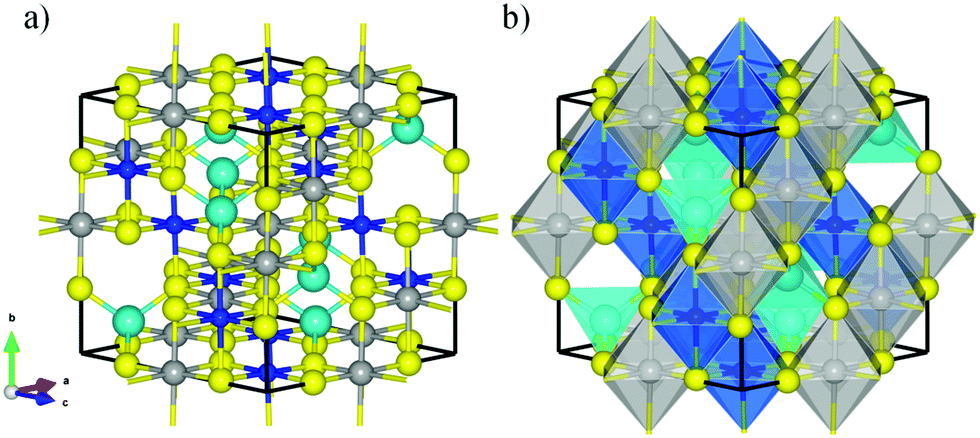 | ||
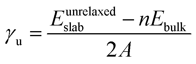
| Fig. 1 (a) Lateral view and (b) polyhedral representation of the conventional unit cell of violarite. Balls in yellow, grey, soft blue, and dark blue represent the S, Fe, NiA, and NiB atoms, respectively. NiA atoms are represented using bigger balls than NiB ions. | ||
| Atom | PW91-D2+U | PBE-D2+U | PBE-D3+U | PW91-D2+U | PBE-D2+U | PBE-D3+U |
|---|---|---|---|---|---|---|
| Q (e−) | m s (μB) | |||||
| Fe | 0.90 | 1.10 | 1.10 | 2.76 | 3.69 | 3.74 |
| NiB | 0.55 | 0.55 | 0.53 | 0.36 | 1.15 | 1.19 |
| NiA | 0.44 | 0.51 | 0.57 | 0.30 | −0.97 | −1.11 |
| S | −0.47 | −0.53 | −0.54 | 0.14 | 0.04 | 0.05 |
3.2. Surface models
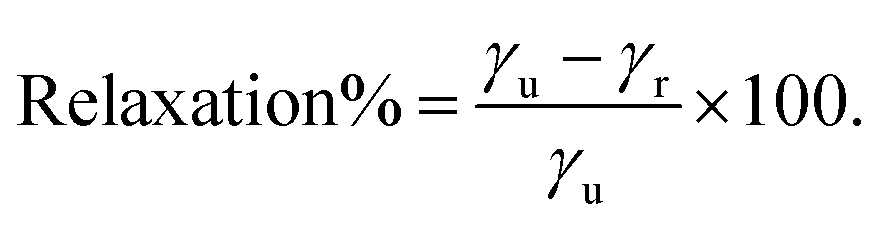
The different non-polar terminations of the two low Miller index surfaces studied here were created from the bulk optimised structure using the METADISE code (minimum energy techniques applied to dislocation, interface and surface energies).47 This code analyses any dipole perpendicular to the surface following the approach pioneered by Tasker.48 Hence, it considers the crystal structure as a stack of atomic planes parallel to the surface plane, where three possibilities arise: type 1 characterised by zero charge planes; type 2 where the planes are charged, but their periodic arrangement cancels the dipole moment; and type 3, where surface reconstructions (e.g. atom vacancies) are required to quench the dipole moment formed by the alternating charged planes. At this point it is also worth noting that the Tasker rule is not broken by surface relaxations as long as the atoms forming the stoichiometric unit do not leave their planes. We have used both possible charge arrangements for the cations, i.e. Ni3+(Fe2+Ni3+)S42− and Ni3+(Fe2.5+Ni2.5+)S42− to ensure the construction of all non-polar slabs. The former distribution of oxidation assumes different charges for the octahedral Ni and Fe ions, which is in agreement with experimental data for the inverse FeNi2S4,42 whereas the latter considers that all the atoms located on the octahedral positions have the same charge (Ni+2.5 and Fe+2.5), in line with the itinerant electron magnetism properties of magnetite (Fe3O4).49To minimise the surface stress, we relaxed different number of atomic layers until energy convergence, leading to a surface model where the top half of the slab was allowed to relax without restrictions, while the bottom half was kept frozen at the atomic bulk positions. The surface energy (γu) of the unrelaxed slabs measures the excess energy of the pristine surface with respect to the bulk, before accounting for surface relaxation, and it is calculated as
 | (2) |
 | (3) |
The stabilization by the surface energy is expressed as a percentage following eqn (4):
 | (4) |
| Eads = ECO2/Surf − (ESurf + ECO2) | (5) |
| Surface termination | γ u (J m−2) | γ r (J m−2) | Relaxation% | Bulk charge |
|---|---|---|---|---|
| PW91-D2+U | ||||
| 1 | 1.50 | 1.24 | 17.33 | Ni3+(Fe2+Ni3+)S42− |
| 2 | 1.27 | 0.69 | 45.67 | Ni 3+ (Fe 2+ Ni 3+ )S 4 2− |
| 3 | 2.01 | 1.67 | 16.92 | Ni3+(Fe2+Ni3+)S42− |
| 4 | 1.27 | 0.87 | 31.50 | Ni3+(Fe2+Ni3+)S42− |
| 5 | 1.50 | 1.01 | 32.67 | Ni3+(Fe2+Ni3+)S42− |
| 6 | 1.95 | 1.65 | 15.38 | Ni3+(Fe2+Ni3+)S42− |
| 7 | 1.02 | 0.69 | 32.35 | Ni3+(Fe2.5+Ni2.5+)S42− |
| 8 | 0.99 | 0.64 | 35.35 | Ni 3+ (Fe 2.5+ Ni 2.5+ )S 4 2− |
| 9 | 1.01 | 0.68 | 32.67 | Ni3+(Fe2.5+Ni2.5+)S42− |
| PBE-D2+U | ||||
| 1 | 1.40 | 1.06 | 24.29 | Ni3+(Fe2+Ni3+)S42− |
| 2 | 1.10 | 0.25 | 77.27 | Ni 3+ (Fe 2+ Ni 3+ )S 4 2− |
| 3 | 1.74 | 1.21 | 30.46 | Ni3+(Fe2+Ni3+)S42− |
| 4 | 1.10 | 0.56 | 49.09 | Ni3+(Fe2+Ni3+)S42− |
| 5 | 1.40 | 0.72 | 48.57 | Ni3+(Fe2+Ni3+)S42− |
| 6 | 1.78 | 0.69 | 61.24 | Ni3+(Fe2+Ni3+)S42− |
| 7 | 0.93 | 0.44 | 52.69 | Ni3+(Fe2.5+Ni2.5+)S42− |
| 8 | 0.87 | 0.42 | 51.72 | Ni3+(Fe2.5+Ni2.5+)S42− |
| 9 | 0.94 | 0.51 | 45.74 | Ni3+(Fe2.5+Ni2.5+)S42− |
| PBE-D3+U | ||||
| 1 | 1.38 | 1.05 | 23.91 | Ni3+(Fe2+Ni3+)S42− |
| 2 | 1.09 | 0.35 | 67.89 | Ni 3+ (Fe 2+ Ni 3+ )S 4 2− |
| 3 | 1.74 | 1.22 | 29.89 | Ni3+(Fe2+Ni3+)S42− |
| 4 | 1.09 | 0.71 | 34.86 | Ni3+(Fe2+Ni3+)S42− |
| 5 | 1.38 | 0.70 | 49.28 | Ni3+(Fe2+Ni3+)S42− |
| 6 | 1.77 | 0.69 | 61.02 | Ni3+(Fe2+Ni3+)S42− |
| 7 | 0.90 | 0.58 | 35.56 | Ni3+(Fe2.5+Ni2.5+)S42− |
| 8 | 0.82 | 0.56 | 31.71 | Ni3+(Fe2.5+Ni2.5+)S42− |
| 9 | 0.91 | 0.58 | 36.26 | Ni3+(Fe2.5+Ni2.5+)S42− |
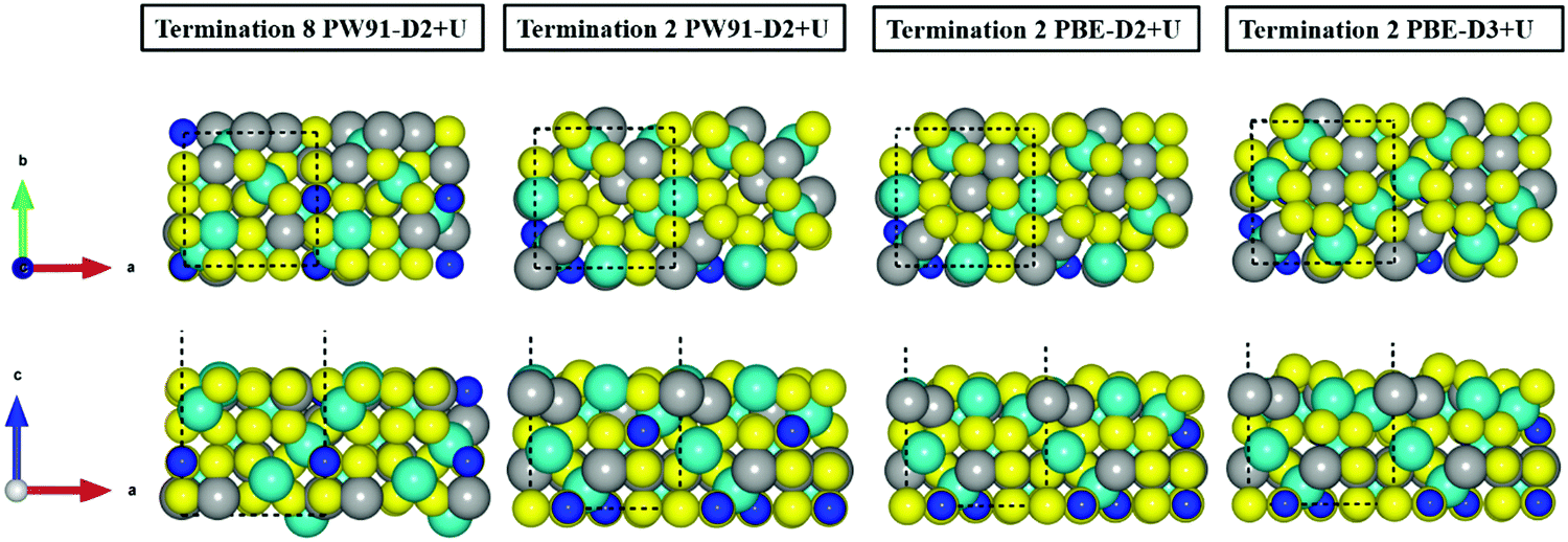 | ||
| Fig. 2 Top (above) and side (bottom) views of the relaxed terminations 8 and 2 of the FeNi2S4{001} surface. Balls in yellow, grey and blue represent the S, Fe and Ni atoms, respectively. NiA atoms are represented with larger balls than NiB ions. | ||
| Surface termination | γ u (J m−2) | γ r (J m−2) | Relaxation% | Bulk charge |
|---|---|---|---|---|
| PW91-D2+U | ||||
| 1 | 1.30 | 0.98 | 24.62 | Ni3+(Fe2+Ni3+)S42− |
| 2 | 1.30 | 1.02 | 21.54 | Ni3+(Fe2+Ni3+)S42− |
| 3 | 2.68 | 1.26 | 52.99 | Ni3+(Fe2+Ni3+)S42− |
| 4 | 1.85 | 0.69 | 62.70 | Ni 3+ (Fe 2.5+ Ni 2.5+ )S 4 2− |
| PBE-D2+U | ||||
| 1 | 1.14 | 0.99 | 13.16 | Ni3+(Fe2+Ni3+)S42− |
| 2 | 1.14 | 1.06 | 7.02 | Ni3+(Fe2+Ni3+)S42− |
| 3 | 1.01 | 0.99 | 1.98 | Ni3+(Fe2+Ni3+)S42− |
| 4 | 1.85 | 0.97 | 47.57 | Ni 3+ (Fe 2.5+ Ni 2.5+ )S 4 2− |
| PBE-D3+U | ||||
| 1 | 1.29 | 1.06 | 17.83 | Ni3+(Fe2+Ni3+)S42− |
| 2 | 1.29 | 0.96 | 25.58 | Ni3+(Fe2+Ni3+)S42− |
| 3 | 2.11 | 1.34 | 36.49 | Ni3+(Fe2+Ni3+)S42− |
| 4 | 1.78 | 0.98 | 44.94 | Ni 3+ (Fe 2.5+ Ni 2.5+ )S 4 2− |
Fig. 3 illustrates the inward movement of FeB and NiA ions, originally sited above the S topmost layer, to (i) the subsurface layer (PW91-D2+U), or to (ii) a single plane in line with the S atoms (PBE-(D2,D3)+U).
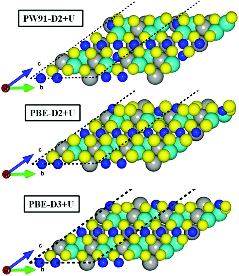 | ||
| Fig. 3 Side view of the relaxed termination 4 of the FeNi2S4{111} surface. Balls in yellow, grey and blue represent the S, Fe and Ni atoms, respectively. NiA atoms are represented using larger balls than NiB ions. | ||
3.3. Interaction between CO2 and FeNi2S4 surfaces
Here we consider the interaction of CO2 with the different surface models described in the previous section. The calculations start by approaching a pre-activated CO2 molecule to all non-equivalent sites on the FeNi2S4{001} and {111} surfaces. A pre-activated geometry was used as an initial set-up, using a bent molecule with apex angle of 130° in three different orientations with respect to the surfaces (see Fig. ESI-3, ESI†). In all our simulations, we placed the CO2 molecule at 1.5 Å from the surface to favour the attractive forces over the repulsive ones between the adsorbate and substrate. However, during geometry optimisation, both the surface and the molecule are free to move and change their geometries. As is also discussed in the following, the CO2 molecule actually becomes linear during the optimisation process, independently of the site, surface termination, and functional used.Regardless of which long-range dispersion correction method was applied, calculations with the PBE+U related functionals resulted in the CO2 molecule recovering its linear conformation on surface termination 2 (Table ESI-2, ESI†). Using PBE-D2+U, we obtained only one geometry with a negative adsorption energy (−0.18 eV), while PBE-D3+U led to an adsorption energy of −0.68 eV due to the reconstruction experienced on the surface upon CO2 interaction (Fig. 4a). In the latter case, the CO2 molecule is located parallel to the surface above the top S surface atom, which migrates from the top layer towards the bulk, and it is aligned with the top S layer. Despite the rather large adsorption energy, the CO2 molecule is not activated but recovers its linear geometry with a CO bond distance of 1.18 Å, as in the gas phase. Furthermore, the distance between surface and the adsorbate is 3.13 Å. In general terms, the simulated wavenumbers of both the asymmetric and symmetric stretching modes remained very similar to the experimental and computational values reported for the isolated CO2 molecule (Table ESI-3, ESI†). The weak binding, which does not depend on the functional used, can be rationalised in terms of the oxygen–sulfur repulsion between the molecule's oxygen lone pairs and the electronic clouds of the sulfur surface atoms. This repulsion is quite clear from the CDD plot in Fig. 4b for the geometry obtained with the PBE-D3+U functional, showing a large electrostatic repulsion between O and S atoms, which is the responsible for the large distance between the molecule and the surface.
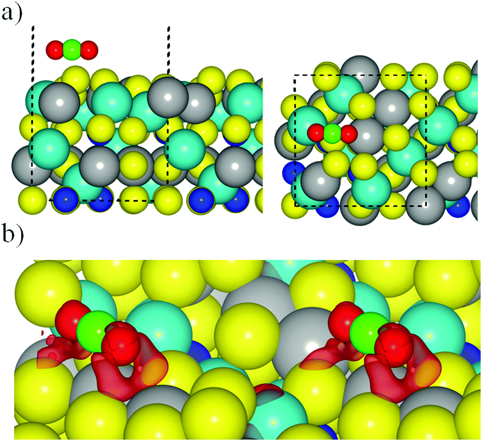 | ||
| Fig. 4 (a) Most favourable geometry for the interaction between the CO2 and termination 2 of FeNi2S4{001} surface using PBE-D3 functional. Side and top views are in left and right panels respectively. (b) CDD plot using PBE-D3 on FeNi2S4[001] surface, where red labels show the negative charge density. The cell has been replicated to improve the visualization. Sphere colouring as in previous figures. | ||
The Grimme dispersion effect on the CO2–surface interactions was quantified through comparison of the most accurate dispersion method (D3) with pure DFT (PBE) calculations. Table ESI-4 (ESI†) shows that D3 increases the CO2 interaction by around 0.14–0.20 eV, slightly lower than has been found in previous works, where the CO2 interaction with carbides and nitrides was studied.50,51
O bonds pointing to NiA atoms in the top layer. In contrast to the {001} surface terminations, there are no differences in the adsorption energies between the most favourable geometries obtained with PBE-D2+U and PBE-D3+U, both of which release 0.56 eV upon CO2 adsorption. The wavenumbers of the fundamental vibrational modes for the most favourable adsorption configurations of CO2 are reported in Tables ESI-3 and ESI-7 (ESI†).
 | ||
| Fig. 5 Adsorption energy of CO2 on magnetite and various iso-structural iron sulfides of different compositions, using different exchange correlation approximations. Left and right panels exhibit the data for the {001} and {111} surfaces, respectively. | ||
This discussion makes it clear that the origin of the weak interaction cannot be attributed to the crystal structure alone, since violarite, greigite and magnetite all feature the spinel structure. Furthermore, although the greigite and magnetite studies were performed using two different functionals, there is enough evidence to claim that the presence of sulfur atoms at the surface hinders CO2 adsorption and activation, as clearly summarized in Fig. 5. Nevertheless, when we compare the results for Fe3S4 and FeNi2S4 surfaces obtained using the same PW91-D2+U computational approach (blue bars in Fig. 5), it appears that the incorporation of Ni atoms in the spinel structure favours the interaction with CO2, although not sufficiently strongly to activate the molecule.
4. Conclusions
This work reports a systematic study of the interaction between CO2 and different terminations and ion arrangements of the {001} and {111} surfaces of the FeNi2S4 spinel violarite, using state of the art DFT-based methods, including dispersion and the on-site Hubbard correction for the 3d levels of the transition metal atoms. The accuracy of the present computational approach is established by comparing to experimental results for the bulk crystal structure. In particular, the PW91-D2+U method provides an optimized value of the lattice parameter in very good agreement with experiment, with values obtained with the PBE-(D2,D3)+U methods being only slightly inferior. The choice of the functional does not play a critical role in the structure of the {111} surface, but in the case of the {001} orientation the most stable surface termination predicted by PW91-D2+U varies from that obtained by PBE-(D2,D3)+U.The interaction of CO2 with both violarite surfaces is moderate, although without activation of the molecule and showing only negligible charge transfer from the surface. This weak interaction is attributed to the repulsion between the lone pair electrons of the oxygen atoms of the CO2 molecule and the spatially extended electronic clouds of the surface sulfur atoms, in agreement with previous findings for the interaction of CO2 with Fe3S4 surfaces. The substitution of Fe atoms by Ni is found to have a strengthening effect on the binding, but not enough to activate the CO2 molecule.
Conflicts of interest
There are no conflicts to declare.Acknowledgements
We acknowledge the Engineering and Physical Sciences Research Council (EPSRC grants no. EP/K035355/2, EP/H046313/1, EP/K001329/1 and EP/K016288/1), Spanish MINECO/FEDER (grant CTQ2015-64618-R) and, in part, Generalitat de Catalunya (grants 2017SGR13 and XRQTC) for funding. This work was performed using the computational facilities of the Advanced Research Computing @ Cardiff (ARCCA) Division, Cardiff University. The authors also acknowledge the use of HPC Wales and associated support services in the completion of this work. S. P.-P. acknowledges financial support from Spanish MINECO predoctoral grant associated to CTQ2012-30751 and F. I. acknowledges additional support from the 2015 ICREA Academia Award for Excellence in University Research. All data created during this research are openly available from the Cardiff University's Research Portal at http://dx.doi.org/10.17035/d.2018.0046360243.References
- X. Lim, Nature, 2015, 526, 628 CrossRef PubMed.
- U. E. I. Administration, International Energy Outlook, Washington DC, 2013, http://www.eia.gov/forecasts/ieo/pdf/0484%282013%29.pdf Search PubMed.
- D. Preti, C. Resta, S. Squarcialupi and G. Fachinetti, Angew. Chem., Int. Ed., 2011, 50, 12551 CrossRef PubMed.
- H.-J. Freund and M. W. Roberts, Surf. Sci. Rep., 1996, 25, 225 CrossRef.
- F. Viñes, A. Borodin, O. Höfft, V. Kempter and F. Illas, Phys. Chem. Chem. Phys., 2005, 7, 3866 RSC.
- G. D. Weatherbee and C. H. Bartholomew, J. Catal., 1984, 87, 352 CrossRef.
- K. P. Kuuhl, T. Hatsukade, E. R. Cave, D. N. Abram, J. Kibsgaard and F. Jaramillo, J. Am. Chem. Soc., 2014, 136, 14107 CrossRef PubMed.
- E. A. Carter, Science, 2008, 321, 800 CrossRef PubMed.
- D. Santos-Carballal, A. Roldán, N. Y. Dzade and N. H. de Leeuw, Philos. Trans. R. Soc., A, 2018, 376, 20170065 CrossRef PubMed.
- H. Furukawa and O. M. Yaghi, J. Am. Chem. Soc., 2009, 131, 8875 CrossRef PubMed.
- A. Demessence, D. M. D’Alessandro, M. L. Foo and J. R. Long, J. Am. Chem. Soc., 2009, 131, 8784 CrossRef PubMed.
- S. Posada-Pérez, F. Viñes, P. J. Ramirez, A. B. Vidal, J. A. Rodriguez and F. Illas, Phys. Chem. Chem. Phys., 2014, 16, 14912 RSC.
- X. Liu, C. Kunkel, P. Ramírez de la Piscina, N. Homs, F. Viñes and F. Illas, ACS Catal., 2017, 7, 4323 CrossRef.
- N. Y. Dzade, A. Roldán and N. H. de Leeuw, J. Chem. Phys., 2015, 143, 094703 CrossRef PubMed.
- A. Roldán and N. H. de Leeuw, Faraday Discuss., 2016, 188, 161 RSC.
- G. Wächtershäuser, Prog. Biophys. Mol. Biol., 1992, 58, 85 CrossRef.
- E. Blöchl, M. Keller, G. Wächtershäuser and K. O. Stetter, Proc. Natl. Acad. Sci. U. S. A., 1992, 89, 8117 CrossRef.
- M. E. Pandelia, W. Nitschke, P. Infossi, M. T. Giudici-Orticoni, E. Bill and W. Lubitz, Proc. Natl. Acad. Sci. U. S. A., 2011, 108, 6097 CrossRef PubMed.
- W. Buckel and R. K. Thauer, Biochim. Biophys. Acta, 2013, 1827, 94 CrossRef PubMed.
- S. Haider, A. Roldan, R. Grau-Crespo and N. H. de Leeuw, J. Phys. Chem. C, 2014, 118, 1958 CrossRef.
- G. Kresse and J. Furthmuüller, Phys. Rev. B: Condens. Matter Mater. Phys., 1996, 54, 11169 CrossRef.
- P. E. Blöchl, Phys. Rev. B: Condens. Matter Mater. Phys., 1994, 50, 17953 CrossRef.
- G. Kresse and D. Joubert, Phys. Rev. B: Condens. Matter Mater. Phys., 1999, 59, 1758 CrossRef.
- H. J. Monkhorst and J. D. Pack, Phys. Rev. B: Solid State, 1976, 13, 5188 CrossRef.
- J. P. Perdew, J. A. Chevary, S. H. Vosko, K. A. Jackson, M. R. Pederson, D. J. Singh and C. Fiolhais, Phys. Rev. B: Condens. Matter Mater. Phys., 1992, 46, 6671 CrossRef.
- J. P. Perdew, J. A. Chevary, S. H. Vosko, K. A. Jackson, M. R. Pederson, D. J. Singh and C. Fiolhais, Phys. Rev. B: Condens. Matter Mater. Phys., 1993, 48, 4978 CrossRef.
- J. P. Perdew, K. Burke and M. Ernzerhof, Phys. Rev. Lett., 1996, 77, 3865 CrossRef PubMed.
- J. P. Perdew, K. Burke and M. Ernzerhof, Phys. Rev. Lett., 1997, 78, 1396 CrossRef.
- S. H. Vosko, L. Wilk and M. Nusair, Can. J. Phys., 1980, 58, 1200 CrossRef.
- S. Grimme, J. Comput. Chem., 2006, 27, 1787 CrossRef PubMed.
- S. Grimme, J. Anthony, S. Ehrlich and H. Krieg, J. Chem. Phys., 2010, 132, 154104 CrossRef PubMed.
- J. P. Prates-Ramalho, J. R. B. Gomes and F. Illas, RSC Adv., 2013, 3, 13085 RSC.
- S. Haider, R. Grau-Crespo, A. J. Devey and N. H. de Leeuw, Geochim. Cosmochim. Acta, 2012, 88, 275 CrossRef.
- S. L. Dudarev, G. A. Botton, S. Y. Savrasov, C. J. Humphreys and A. P. Sutton, Phys. Rev. B: Condens. Matter Mater. Phys., 1998, 57, 1505 CrossRef.
- V. I. Anisimov, M. A. Korotin, J. Zaanen and O. K. Andersen, Phys. Rev. Lett., 1998, 68, 345 CrossRef PubMed.
- J. P. Perdew, A. Ruzsinszky, G. I. Csonka, O. A. Vydrov, G. E. Scuseria, L. A. Constantin, X. Zhou and K. Burke, Phys. Rev. Lett., 2008, 100, 136406 CrossRef PubMed.
- R. F. W. Bader, Atoms in Molecules: A Quantum Theory, Oxford University Press, Oxford, UK, 1990 Search PubMed.
- G. Henkelman, A. Arnaldsson and H. Jonsson, Comput. Mater. Sci., 2006, 36, 354 CrossRef.
- W. Tang, E. Sanville and G. Henkelman, J. Phys.: Condens. Matter, 2009, 21, 084204 CrossRef PubMed.
- C. Tenailleau, B. Etschmann, R. M. Ibberson and A. Pring, Am. Mineral., 2006, 91, 1442 CrossRef.
- D. J. Vaughan and J. R. Craig, Am. Mineral., 1985, 70, 1036 Search PubMed.
- J. Charnock, C. D. Garner, R. A. D. Pattrick and D. J. Vaughan, Am. Mineral., 1990, 75, 247 Search PubMed.
- D. Santos-Carballal, A. Roldan, R. Grau-Crespo and N. H. de Leeuw, Phys. Rev. B: Condens. Matter Mater. Phys., 2015, 91, 195106 CrossRef.
- P. Janthon, S. M. Kozlov, F. Viñes, J. Limtrakul and F. Illas, J. Chem. Theory Comput., 2013, 9, 163 CrossRef PubMed.
- C. Tenailleau, B. Etschmann, R. M. Ibberson and A. Pring, Am. Mineral., 2006, 91, 1442 CrossRef.
- C. Tenailleau, A. Pring, B. Etschmann, J. Brugger, B. Grguric and A. Putnis, Am. Mineral., 2006, 91, 706 CrossRef.
- G. W. Watson, E. T. Kelsey, N. H. de Leeuw, D. J. Harris and S. C. Parker, J. Chem. Soc., Faraday Trans., 1996, 92, 433 RSC.
- P. W. Tasker, J. Phys. C: Solid State Phys., 1979, 12, 4977 CrossRef.
- D. Santos-Carballal, A. Roldan, R. Grau-Crespo and N. H. de Leeuw, Phys. Chem. Chem. Phys., 2014, 16, 21082 RSC.
- R. Morales-Salvador, A. Morales-Gracia, F. Viñes and F. Illas, Phys. Chem. Chem. Phys., 2018, 20, 17117 RSC.
- A. Morales-Gracia, A. Fernandez-Fernandez, F. Viñes and F. Illas, J. Mater. Chem. A, 2018, 6, 3381 RSC.
Footnote |
| † Electronic supplementary information (ESI) available. See DOI: 10.1039/c8cp03430c |
| This journal is © the Owner Societies 2018 |