 Open Access Article
Creative Commons Attribution 3.0 Unported Licence
Self-assembly and friction of glycerol monooleate and its hydrolysis products in bulk and confined non-aqueous solvents†
Joshua L.
Bradley-Shaw
a,
Philip J.
Camp
 *a,
Peter J.
Dowding
b and
Ken
Lewtas
ac
aSchool of Chemistry, University of Edinburgh, David Brewster Road, Edinburgh EH9 3FJ, Scotland, UK. E-mail: philip.camp@ed.ac.uk
bInfineum UK Ltd, P.O. Box 1, Milton Hill, Abingdon OX13 6BB, UK
cLewtas Science & Technologies, 246 Banbury Road, Oxford OX2 7DY, UK
First published on 22nd June 2018
Abstract
Atomistic molecular dynamics simulations are used to study the self-assembly and friction of glycerol monooleate mixed with oleic acid, glycerol, calcium oleate, or water in n-heptane and toluene solvents. The aim is to determine how chemical degradation products of glycerol monooleate could lead to changes in structural and frictional properties. In bulk solution, almost all mixtures studied contain self-assembled reverse micelles. Under confinement between sheared mica surfaces, the reverse micelles disintegrate, but the distribution of molecules between the surfaces and the centre of the fluid layer depends sensitively on the chemical composition, with more polar mixtures showing stronger adsorption. The measured kinetic friction coefficient is correlated with the extent of surface adsorption: while degradation products lead to increases in the friction coefficient in most cases, all changes are more pronounced when there is less surface adsorption.
1 Introduction
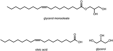
Lubricants are an important and widely used class of industrial chemicals. In engine applications, they are usually composed of a base oil (typically a mixture of C20–C40 raffinate products) and various additives such as viscosity modifiers, dispersants, detergents, friction modifiers, and anti-wear compounds. One of the key purposes of a lubricant is to reduce frictional forces between moving parts of a machine, and so friction modifiers are crucial components of modern lubricant formulations. In the classic Bowden–Tabor model, friction modifiers are surfactant-type molecules such as fatty acids that adsorb preferentially at the solid–oil interface to form a monolayer or multilayers, and provide a soft barrier between moving solid surfaces close to contact.1–3Glycerol monooleate (GMO) is a friction modifier that is used extensively in the lubricant industry; its molecular structure is shown in Fig. 1. It has been claimed4 that GMO lubricates metal surfaces by being hydrolysed to oleic acid (OlH) (also shown in Fig. 1) which then adsorbs on to the surfaces and prevents metal–metal contact as per the Bowden–Tabor picture.2 This is reminiscent of an old model of steel surfaces being lubricated by fatty acids produced through hydrolysis of esters by small amounts of water.5 In contrast, diamond-like carbon surfaces are lubricated by interaction with GMO in its original form.6,7
GMO is a non-ionic surfactant, and when dissolved in non-aqueous media, it is known to self-assemble into reverse micelles (RMs), with the polar head groups in the interior of the RM.8–12 In the original experimental work by Shrestha et al.8–11 the presence of RMs was determined by small-angle X-ray scattering. In subsequent work by the current authors, the sizes and structures of RMs were detailed by combining small-angle neutron scattering (SANS) and molecular-dynamics (MD) simulations.12 A GMO RM is typically around 15 Å in radius, and contains 20–30 molecules depending on solvent. Aromatic solvents penetrate the RM more than aliphatic solvents, while the RM size remains roughly constant, and so there are fewer GMO molecules per RM in aromatic solvents. Small polar molecules, such as water, ethanol, or acetic acid are absorbed into the interior of the RM.12 RM formation may play a role in friction modification, if only as a competing mechanism for the normal picture of adsorption at the solid–oil interface. Recently, MD simulations have been used to examine the role of GMO RMs in modifying the frictional forces between sheared parallel mica surfaces.13 With n-heptane as the base oil, preformed GMO RMs remain intact under both static and shear conditions, and lead to a slightly lower friction coefficient than if the GMO molecules are adsorbed equally on both surfaces. With toluene as the base oil, the RMs are less stable and are seen to disintegrate on the application of shear. Added water at low concentrations (1 wt%) leads to a reduction of friction because of its own lubricating effect at the mica surface and/or because it stabilises RMs at the surface.
GMO may be hydrolysed at engine temperatures to form oleic acid and glycerol (shown in Fig. 1), and if oleic acid is not as good a friction modifier as GMO, then this could lead to a reduction in performance. The hydrolysis of GMO was studied by Murgia et al.14 who found that the product composition depends strongly on the water content and external conditions. Aqueous potassium permanganate oxidises GMO to glycerol-1-o-nonanoic acid and nonanoic acid, although the necessary conditions for such oxidations are unlikely to occur in engines. In the context of frying food, the oxidation products of methyl oleate (similar to GMO) have been studied using GC-FTIR and GC-MS techniques at 180 °C.15 Here a huge range of carbonyl compounds and alcohols is formed.
Returning to oleic acid, there will always be free metallic cations such as Ca2+, Fe2+, or Pb2+ dispersed in the lubricant, arising either from calcium carbonate nanoparticle detergents, or from the engine parts. This raises the possibility of forming metal-oleate salts with stoichiometry M(oleate)2. Oleic acid could also undergo further degradation in the engine, with oxidations to form epoxides, dihydroxystearic acids, and keto-stearic acids being likely pathways.16 These oxidation products could subsequently break down to form smaller alcohols.
The range of possible products from hydrolysis of GMO, and its subsequent breakdown, is bewildering. It would be impractical to embark on a comprehensive study of the structural and frictional properties of all possible degradation products. Therefore, the focus of this work will be a comparative assessment of the self-assembly and frictional properties of GMO, oleic acid, glycerol, and calcium oleate (CaOl2), with and without added water. This selection of compounds was made on the basis that fatty acids have long been implicated in lubrication,4,5 glycerol would be the other product from the hydrolysis of GMO to form oleic acid, and there is an abundant source of calcium in lubricant detergents. This assessment will be carried out using atomistic MD simulations of lubricants made up of a simple base oil (n-heptane or toluene) containing friction modifiers, with and without added water. The self-assembly of the additives will be studied in bulk solutions, while the frictional properties will be assessed for the fluid confined and sheared between parallel mica surfaces.
Atomistic molecular simulations have been used to study the frictional properties of a very wide range of molecular systems,17 including polymers and hydrocarbons,18–24 silanes,25 fatty acids and amines,26–32 glycerin,33 glycerides,34 zinc dialkyldithiophosphates,35 molybdenum sulfides,36,37 room-temperature ionic liquids,38,39 and carbon nanoparticles.40 In very recent work, Ewen et al. carried out a comprehensive survey of various organic friction modifiers adsorbed on iron oxide surfaces, and lubricated by a very thin film of hexadecane.41 Using non-equilibrium MD simulations, it was found that molecules with glyceride head groups reduce friction more than those with amide or carboxylic head groups.
The self-assembly of GMO and its hydrolysis products in bulk solution will be studied under ambient conditions, T = 298 K and P = 1 atm. Under confinement between mica surfaces, the load will be increased substantially to the equivalent of P = 1000 atm, and the shear rate will be in the region of 109 s−1. These numbers may appear astronomically high, but the transient loads in engine crankcases can be as high as 104 atm, and surface asperities separated by 1 nm and moving at a relative velocity of 1 m s−1 give a local shear rate of 109 s−1. The choice of mica surfaces is motivated by the possibility of testing the predictions of this work with surface force apparatus, or in situ neutron or X-ray reflectometry measurements, both of which require smooth surfaces. Finally, the solutions will be considered in either n-heptane or toluene to facilitate future SANS studies that rely on readily available deuterated solvents.
The rest of the article is organised as follows. The model and methods are described in Section 2, the results are presented in Section 3, and Section 4 concludes the article.
2 Model and methods
Atomistic MD simulations were performed using the LAMMPS software.42,43 Self-assembly of friction modifiers in bulk solutions was studied using equilibrium MD simulations in the isothermal–isobaric (NPT) ensemble. Frictional properties were calculated in non-equilibrium MD simulations under fixed load and surface sliding speed. In all cases, initial configurations of the fluids were generated using Packmol.44,45All intramolecular and intermolecular interactions in bulk solutions were described using the OPLS-AA force field46 and the SPC/E water model. Cross interactions were computed using the Lorentz–Berthelot rule. Solutions were equilibrated in the canonical (NVT) ensemble for 0.5 ns at temperature T = 373 K and then for 0.5 ns at T = 298 K. The simulation was then switched to the NPT ensemble with pressure P = 1 atm, and equilibrated for 5 ns, which was found to be sufficient for completing any self-assembly processes. Finally, a production run of 5 ns was carried out. The temperature and pressure were controlled using the Nosé–Hoover thermostat/barostat. Periodic boundary conditions were applied in all three directions, and the long-range Coulombic interactions were handled using the particle–particle particle–mesh implementation of the Ewald sum with conducting boundary conditions. The equations of motion were integrated using the velocity Verlet algorithm with a timestep of 1 fs.
The compositions of the bulk solutions are given in Table 1. In each case, the total content of additive (GMO, OlH, Gly, CaOl2) is fixed at 10 wt%. This is higher than in bulk lubricant formulations, but it is normal for experimental measurements (e.g. SANS) on bulk solutions.12 Moreover, under confinement between moving engine parts, some of the base oil gets squeezed out, meaning that the local concentration of additive could be a lot higher than in the bulk formulation.47,48 The numbers of organic additive molecules in n-heptane and toluene are 30 and 20, respectively, equal to the aggregation numbers in RMs.12 Mixtures were generated by substituting GMO with other molecules, and then adjusting the number of solvent molecules to give the desired total additive content of 10 wt%. In each case, the GMO content is close to either 0 wt%, 2.5 wt%, 5 wt%, or 10 wt%, and one or more hydrolysis products make up the rest of the additive content. In cases with 1 wt% added water, the total organic additive content is still close to 10 wt%.
![[small gamma, Greek, dot above]](https://www.rsc.org/images/entities/i_char_e0a2.gif) eff is the shear rate in the centre of the fluid layer, λ is the stick length, and μ is the kinetic friction coefficient, all from non-equilibrium MD simulations with a relative sliding velocity vs = 20 m s−1
eff is the shear rate in the centre of the fluid layer, λ is the stick length, and μ is the kinetic friction coefficient, all from non-equilibrium MD simulations with a relative sliding velocity vs = 20 m s−1
| GMO | OlH | H2O | Gly | CaOl2 | Solvent | wt% GMO | N atom | ρ/kg m−3 | Structure | R g/Å | H z /Å |
![[small gamma, Greek, dot above]](https://www.rsc.org/images/entities/i_char_e0a2.gif) eff/109 s−1
eff/109 s−1 |
λ/Å | μ |
|---|---|---|---|---|---|---|---|---|---|---|---|---|---|---|
| GMO and OlH in n-heptane | ||||||||||||||
| 30 | 961H | 10.0 | 24![[thin space (1/6-em)]](https://www.rsc.org/images/entities/char_2009.gif) 053 053 |
707 | 1RM | 14.9(4) | 73.8 | 3.27 | 6.3 | 0.0165(49) | ||||
| 23 | 7 | 914H | 8.1 | 22![[thin space (1/6-em)]](https://www.rsc.org/images/entities/char_2009.gif) 895 895 |
687 | 2RM | 14.3(7) | 67.6 | 2.88 | −0.9 | 0.0269(49) | |||
| 15 | 15 | 861H | 5.6 | 21![[thin space (1/6-em)]](https://www.rsc.org/images/entities/char_2009.gif) 588 588 |
687 | None | 63.8 | 3.22 | 0.8 | 0.0282(49) | ||||
| 7 | 23 | 808H | 2.8 | 20![[thin space (1/6-em)]](https://www.rsc.org/images/entities/char_2009.gif) 281 281 |
686 | 1C | 60.1 | 3.76 | 3.5 | 0.0299(49) | ||||
| 30 | 761H | 0.0 | 19![[thin space (1/6-em)]](https://www.rsc.org/images/entities/char_2009.gif) 123 123 |
681 | 1RM, 2D | 17.0(4) | 59.3 | 3.53 | 1.3 | 0.0325(49) | ||||
| GMO and OlH in toluene | ||||||||||||||
| 20 | 697T | 10.0 | 11![[thin space (1/6-em)]](https://www.rsc.org/images/entities/char_2009.gif) 755 755 |
831 | 1RM | 16.1(4) | 39.1 | 8.01 | 7.1 | 0.0416(47) | ||||
| 15 | 5 | 660T | 7.9 | 11![[thin space (1/6-em)]](https://www.rsc.org/images/entities/char_2009.gif) 145 145 |
838 | None | 38.3 | 7.98 | 6.6 | 0.0381(49) | ||||
| 10 | 10 | 624T | 5.6 | 10![[thin space (1/6-em)]](https://www.rsc.org/images/entities/char_2009.gif) 550 550 |
836 | None | 36.4 | 7.94 | 5.6 | 0.0409(49) | ||||
| 5 | 15 | 588T | 3.0 | 9955 | 836 | None | 34.4 | 8.77 | 5.8 | 0.0436(49) | ||||
| 20 | 552T | 0.0 | 9360 | 826 | None | 32.6 | 9.37 | 5.6 | 0.0453(49) | |||||
| GMO, OlH, and H2O in n-heptane | ||||||||||||||
| 30 | 60 | 952H | 10.0 | 24![[thin space (1/6-em)]](https://www.rsc.org/images/entities/char_2009.gif) 026 026 |
711 | 1RM | 14.9(4) | 71.7 | 3.11 | 3.7 | 0.0195(49) | |||
| 23 | 7 | 60 | 914H | 8.0 | 23![[thin space (1/6-em)]](https://www.rsc.org/images/entities/char_2009.gif) 075 075 |
695 | 1RM, 1C | 15.7(4) | 67.8 | 3.35 | 4.0 | 0.0271(66) | ||
| 15 | 15 | 60 | 861H | 5.5 | 21![[thin space (1/6-em)]](https://www.rsc.org/images/entities/char_2009.gif) 768 768 |
692 | 2RM | 14.4(5) | 64.1 | 3.50 | 3.5 | 0.0290(65) | ||
| 7 | 23 | 60 | 808H | 2.7 | 20![[thin space (1/6-em)]](https://www.rsc.org/images/entities/char_2009.gif) 461 461 |
692 | 2RM, 1C | 14.5(8) | 60.4 | 3.69 | 3.1 | 0.0315(65) | ||
| 30 | 60 | 800H | 0.0 | 20![[thin space (1/6-em)]](https://www.rsc.org/images/entities/char_2009.gif) 200 200 |
690 | 1RM, 4C | 15.1(6) | 59.6 | 3.79 | 3.4 | 0.0304(69) | |||
| GMO, OlH, and H2O in toluene | ||||||||||||||
| 20 | 40 | 690T | 10.0 | 11![[thin space (1/6-em)]](https://www.rsc.org/images/entities/char_2009.gif) 770 770 |
840 | 1RM | 14.0(4) | 40.2 | 7.68 | 7.1 | 0.0372(49) | |||
| 15 | 5 | 40 | 660T | 7.8 | 11![[thin space (1/6-em)]](https://www.rsc.org/images/entities/char_2009.gif) 265 265 |
845 | 1RM | 14.9(6) | 33.2 | 8.99 | 5.5 | 0.0317(69) | ||
| 10 | 10 | 40 | 624T | 5.5 | 10![[thin space (1/6-em)]](https://www.rsc.org/images/entities/char_2009.gif) 670 670 |
844 | 1RM | 15.0(5) | 31.6 | 9.65 | 5.4 | 0.0328(68) | ||
| 5 | 15 | 40 | 588T | 2.9 | 10![[thin space (1/6-em)]](https://www.rsc.org/images/entities/char_2009.gif) 075 075 |
841 | 2RM, 1C | 12.1(7) | 30.0 | 10.0 | 5.0 | 0.0342(66) | ||
| 20 | 40 | 575T | 0.0 | 9825 | 838 | 1RM, 5C | 12.2(4) | 29.3 | 10.5 | 5.1 | 0.0337(69) | |||
| GMO, OlH, and Gly in n-heptane | ||||||||||||||
| 30 | 961H | 10.0 | 24![[thin space (1/6-em)]](https://www.rsc.org/images/entities/char_2009.gif) 053 053 |
707 | 1RM | 14.9(4) | 73.8 | 3.27 | 6.3 | 0.0165(49) | ||||
| 23 | 7 | 7 | 971H | 7.6 | 24![[thin space (1/6-em)]](https://www.rsc.org/images/entities/char_2009.gif) 304 304 |
688 | 1RM, 1C | 13.8(5) | 71.6 | 2.87 | 1.0 | 0.0275(65) | ||
| 15 | 15 | 15 | 984H | 4.9 | 24![[thin space (1/6-em)]](https://www.rsc.org/images/entities/char_2009.gif) 627 627 |
688 | 1RM, 2C | 11.8(3) | 72.4 | 3.21 | 5.0 | 0.0262(47) | ||
| 7 | 23 | 23 | 998H | 2.2 | 24![[thin space (1/6-em)]](https://www.rsc.org/images/entities/char_2009.gif) 973 973 |
688 | 2RM, 1C | 12.2(4) | 73.4 | 3.21 | 5.5 | 0.0254(47) | ||
| 30 | 30 | 1009H | 0.0 | 25![[thin space (1/6-em)]](https://www.rsc.org/images/entities/char_2009.gif) 247 247 |
688 | 2RM, 1C | 11(1) | 75.3 | 3.44 | 8.6 | 0.0248(47) | |||
| GMO, OlH, and Gly in toluene | ||||||||||||||
| 20 | 697T | 10.0 | 11![[thin space (1/6-em)]](https://www.rsc.org/images/entities/char_2009.gif) 755 755 |
831 | 1RM | 16.1(4) | 39.1 | 8.01 | 7.1 | 0.0416(47) | ||||
| 15 | 5 | 5 | 705T | 7.4 | 11![[thin space (1/6-em)]](https://www.rsc.org/images/entities/char_2009.gif) 890 890 |
835 | 1RM, 2C | 14(1) | 40.8 | 7.53 | 7.1 | 0.0379(65) | ||
| 10 | 10 | 10 | 713T | 4.9 | 12![[thin space (1/6-em)]](https://www.rsc.org/images/entities/char_2009.gif) 025 025 |
835 | 2RM, 1C | 15(1) | 41.2 | 7.44 | 7.2 | 0.0386(65) | ||
| 5 | 15 | 15 | 722T | 2.4 | 12![[thin space (1/6-em)]](https://www.rsc.org/images/entities/char_2009.gif) 175 175 |
837 | 2RM, 1C | 12.9(7) | 41.7 | 6.49 | 5.4 | 0.0371(65) | ||
| 20 | 20 | 732T | 0.0 | 12![[thin space (1/6-em)]](https://www.rsc.org/images/entities/char_2009.gif) 340 340 |
837 | 2RM, 1C | 12.1(8) | 42.2 | 6.56 | 5.9 | 0.0343(66) | |||
| GMO and CaOl2 in n-heptane | ||||||||||||||
| 30 | 961H | 10.0 | 24![[thin space (1/6-em)]](https://www.rsc.org/images/entities/char_2009.gif) 053 053 |
707 | 1RM | 14.9(4) | 73.8 | 3.27 | 6.3 | 0.0165(49) | ||||
| 23 | 4 | 953H | 7.7 | 23![[thin space (1/6-em)]](https://www.rsc.org/images/entities/char_2009.gif) 842 842 |
690 | 1RM | 15.6(4) | 68.0 | 3.02 | 0.9 | 0.0268(49) | |||
| 15 | 7 | 888H | 5.4 | 22![[thin space (1/6-em)]](https://www.rsc.org/images/entities/char_2009.gif) 148 148 |
688 | 1RM | 15.8(5) | 61.4 | 3.11 | −1.5 | 0.0279(49) | |||
| 7 | 11 | 820H | 2.7 | 20![[thin space (1/6-em)]](https://www.rsc.org/images/entities/char_2009.gif) 492 492 |
692 | 2RM | 12.7(4) | 58.6 | 3.30 | −1.0 | 0.0317(50) | |||
| 15 | 812H | 0.0 | 20![[thin space (1/6-em)]](https://www.rsc.org/images/entities/char_2009.gif) 281 281 |
731 | 2RM | 10.9(5) | 60.3 | 3.36 | 0.4 | 0.0292(50) | ||||
| GMO and CaOl2 in toluene | ||||||||||||||
| 20 | 697T | 10.0 | 11![[thin space (1/6-em)]](https://www.rsc.org/images/entities/char_2009.gif) 755 755 |
831 | 1RM | 16.1(4) | 39.1 | 8.01 | 7.1 | 0.0416(47) | ||||
| 15 | 3 | 699T | 7.5 | 11![[thin space (1/6-em)]](https://www.rsc.org/images/entities/char_2009.gif) 781 781 |
832 | 1RM | 13.7(4) | 40.6 | 8.04 | 7.9 | 0.0402(50) | |||
| 10 | 5 | 643T | 5.4 | 10![[thin space (1/6-em)]](https://www.rsc.org/images/entities/char_2009.gif) 830 830 |
838 | 2RM | 13.1(4) | 37.4 | 6.56 | 3.5 | 0.0422(49) | |||
| 5 | 7 | 586T | 3.0 | 9864 | 834 | 2RM | 12.3(9) | 37.4 | 7.80 | 5.9 | 0.0413(50) | |||
| 10 | 589T | 0.0 | 9905 | 888 | 2RM | 11.5(2) | 34.4 | 7.34 | 3.6 | 0.0447(50) | ||||
Simulations of the fluid confined by mica surfaces and under shear conditions were carried out as detailed in earlier work.13 Mica was described using the INTERFACE-PCFF toolkit from the Heinz group.49–52 For internal consistency, the INTERFACE-PCFF force field was used for both the mica surfaces and the confined fluid. As shown explicitly in ref. 13, the OPLS-AA and INTERFACE-PCFF force fields give practically identical results for the bulk-solution densities and sizes of self-assembled RMs. A 52 Å × 54 Å × 10 Å surface of mica with stoichiometric aluminium defects was produced by tiling 10 × 6 × 1 unit cells (each with dimensions 5.1918 Å × 9.0153 Å × 10.0228 Å). One surface contained 2520 atoms. The surface was equilibrated under NPT conditions for 1 ns to eliminate any structural defects or warping. Initial fluid configurations of about 80 Å in thickness and without preformed RMs were then prepared as described above, and placed between two mica surfaces. Simulations were carried out under a constant external load in the z direction corresponding to a pressure of 1000 atm, by applying forces to the outermost atoms in the top surface, and keeping fixed the z coordinates of the outermost atoms in the bottom surface. Periodic boundary conditions were applied in the x and y directions only. The confined-fluid systems were first equilibrated under static conditions for 1 ns. Then, shear conditions were applied by giving the top and bottom surfaces equal and opposite constant velocities ±vs/2 in the x direction, so that the relative sliding velocity is vs. A Nosé–Hoover thermostat was applied only in the y direction (perpendicular to the shear plane) so as not to disturb the fluid velocity profile vx(z). Simulations were equilibrated until the velocity profile reached a steady state, typically within 5 ns. Then a production run of 5 ns was carried out, and the lateral frictional force (FL) and normal force (FN) on each surface were calculated. The extended Amontons–Coulomb law is FL = F0 + μFN where F0 is the Derjaguin offset representing adhesive forces between the surfaces, and μ is the kinetic friction coefficient. For the lubricated systems under consideration here, and particularly at the very high loads applied, μFN ≫ F0 and hence the friction coefficient can be estimated from a single simulation using the simple formula μ ≈ FL/FN. This has been shown to be good approximation under the conditions considered here.30
3 Results
All of the key numerical results are collated in Table 1.3.1 Self-assembly in bulk solution
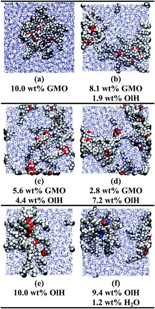
The simulations of GMO and OlH in n-heptane show that RMs can form when either component is in the majority, but that small or equivalent concentrations of OlH disrupt GMO RM formation. Some end-of-run snapshots are shown in Fig. 2(a–e). These images show that with 5.6 wt% GMO, although clustering is evident, the aggregates cannot be described as RMs, while with an excess of GMO or OlH, well-defined aggregates are formed. The presence of one or two micelles is recorded in the ‘Structure’ column of Table 1 by 1RM or 2RM, respectively. The presence of a large cluster is denoted by 1C, and if two molecules are found to form a dimer, then this is denoted by 1D. These designations are determined by visual inspection of the end-of-run snapshots. The average radius of gyration Rg of any RMs is also given in Table 1. This was computed using the inertia tensor of the RM given by | (1) |
 | (2) |
 is the total mass of the RM. This approach was used in earlier work, and the results were in excellent agreement with experimental measurements of Rg using SANS.12 In this work, and for all compositions, Rg is in the region of 11–17 Å.
In toluene the effect of changing GMO to OlH is more pronounced: a GMO solution forms a single RM, but the addition of any OlH leads to the disappearance of the RM. In earlier work, it was found that toluene penetrates into the GMO RM far more than does n-heptane, leading to a larger RM despite there being fewer GMO molecules.12 The simulation results suggest that OlH is unable to stabilise a RM in a more penetrating solvent.
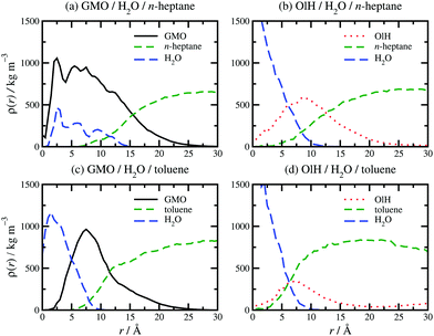
The presence of approximately 1 wt% water in GMO and OlH solutions leads to RM formation at all compositions, and a small degree of clustering of molecules not incorporated in to the RM. As an example, a snapshot from a system with 9.4 wt% OlH and 1.2 wt% H2O in n-heptane is shown in Fig. 2(f). The aggregation numbers of GMO RMs in n-heptane and toluene are 30 and 20, respectively, but these are likely to change as GMO is replaced with OlH. The procedure of adding or subtracting additive molecules until there is just one complete RM has not been carried out in this work, and so any excess additive molecules are left to form small clusters. In n-heptane with water, the sizes of the GMO, OlH, and mixed RMs are similar (Rg = 14.4–15.7 Å), while in toluene with water, an OlH RM (Rg = 12.2 Å) is significantly smaller than a mixed GMO/OlH RM (Rg = 15.0 Å). Note that Rg is computed for the additive and water combined, and so these observations are correlated with the distributions of all species in the RMs. Fig. 3 shows the local density profiles of GMO or OlH, water, and solvent as functions of the radial distance from the centre of mass of the RM. Comparing Fig. 3(a and b), the n-heptane density profile is very similar in each case, and so the extent of the RM (including both additive and water) is the same. Nonetheless, water is more strongly localised in the OlH RM than in the GMO RM, and with the OlH expelled from the centre to form a surfactant-like corona. Comparing Fig. 3(c and d), both GMO and OlH form a surfactant-like layer between the water core and the toluene, but OlH has a lower mass than GMO and so the radius of gyration of the equivalent ellipsoid is lower.
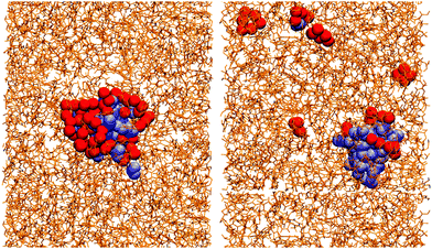
Essentially, OlH doesn't have enough polar groups to fully surround the water core, while GMO does. This means that water is more exposed to solvent in an OlH RM than in a GMO RM. This is illustrated in Fig. 4 which shows the solvent in stick representation, the head-group oxygen atoms in GMO and OlH, and the water molecules. The water core in the GMO RM is almost completely coordinated by the polar atoms of the glycerol and oleate moieties, while the water core of the OlH RM is highly exposed to the toluene.
When GMO is hydrolysed, both OlH and Gly are produced. In all proportions, and in both n-heptane and toluene, mixtures of GMO, OlH, and Gly form RMs, with Rg of the pure-GMO RMs being slightly larger than the rest. Mixtures of GMO and CaOl2 also form RMs in both n-heptane and toluene. GMO alone forms single RMs, but CaOl2 alone forms two smaller RMs. Due to the low dielectric constants of the solvents, charge separation is unfavourable and the Ca2+ ions are strongly coordinated by the anionic head groups of the oleate ions, which leads to smaller RMs.
To summarise, OlH forms mixed micelles with GMO when there is another polar species present, be it water or Gly. Without the polar species present, OlH will form micellar structures in n-heptane but not in toluene. CaOl2 and GMO form mixed micelles, but increasing the CaOl2 content leads to more and smaller RMs.
3.2 Structure and friction under confinement and shear
The structure, velocity profile, and friction coefficient of the confined fluid under shear are now discussed. The structure of the confined fluid can be characterised with the mass-density profile, ρ(z), for each component. Results for GMO in n-heptane and toluene sheared at 10 m s−1 were reported in ref. 13. Fig. 5(a and b) shows ρ(z) for GMO in n-heptane and toluene sheared at 20 m s−1. The essential point is that in both solvents, the GMO becomes strongly associated with the surfaces, and the concentration is practically zero in the middle of the fluid layer. The density oscillations for the solvent are caused by layering of the molecules near the mica surfaces, with the period corresponding to the width of the molecular layers. For n-heptane, this is comparable to the diameters of the CH2 and CH3 groups, because the molecules very close to the surfaces are aligned in a parallel orientation. This behaviour has been seen with many long-chain hydrocarbon solvents confined between hard surfaces.13,29,30 For toluene, the peaks are broader because there is no strong orientational ordering of the molecules near the surfaces, and so the layer width corresponds to an average molecular diameter. In addition, the extent of layering in toluene is less than in n-heptane, reflecting less positional and orientational ordering of the less elongated molecules. In earlier work, it was shown that the application of shear generally causes surface-adsorbed additive molecules to tilt, while the overall mass-density profiles change remarkably little.29,30 Self-assembled structures, such as RMs, may remain intact, migrate to a surface, or disintegrate entirely.13 Here the emphasis is on the distribution of additives within the confined fluid under shear, and its connection with the measured velocity profiles and friction coefficients. [The velocity profiles in Fig. 5(c and d) are discussed separately below.]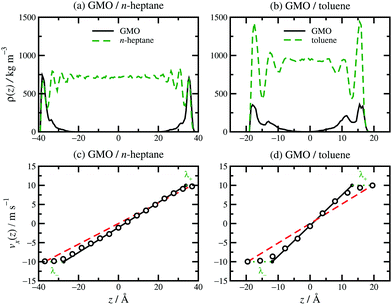 | ||
| Fig. 5 Local density profiles and velocity profiles for GMO in n-heptane [a and c] and toluene [b and d]: (a) ρ(z) for GMO in n-heptane; (b) ρ(z) for GMO in toluene; (c) vx(z) for GMO in n-heptane; (d) vx(z) for GMO in toluene. z is the distance from the middle of the fluid layer. In (c and d), the MD simulation results are shown as unfilled circles, fits to eqn (3) as solid black lines, vsz/Hz as red dashed lines, and λ± as green dotted lines. | ||
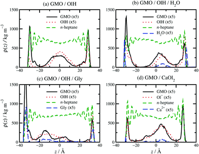
Some examples of mass-density profiles for mixtures are shown in Fig. 6 for systems with roughly 5 wt% GMO in n-heptane. Clearly, the main difference from the pure-GMO solutions is that there are additive structures in the middle of the fluid layer. GMO and OlH alone [Fig. 6(a)] form adsorbed layers on both surfaces, and a clustered structure in the middle of the fluid layer. Added water [Fig. 6(b)] is distributed between the surfaces and the centre of the GMO/OlH cluster in the middle of the fluid layer. The surface-adsorbed water forms a film between mica and GMO/OlH; this was also observed in ref. 13. Surface-adsorbed water remains fluid due to its high translational and rotational mobilities, and so it represents an ultrathin lubricating layer.53,54 Added Gly [Fig. 6(c)] remains closely associated with the GMO and OlH, but the non-adsorbed additives are not strongly localised in the centre of the fluid layer. Added CaOl2 [Fig. 6(d)] also remains associated with the GMO, but there is a clear distinction between surface-adsorbed and fully solvated molecules.
Replacing GMO with OlH means that the additive becomes less polar, and less strongly adsorbed at the solid–fluid interface. This is apparent from Fig. 6(a) which shows a higher mass density of OlH than GMO near the centre of fluid layer, and slightly lower mass density at the surfaces. Adding water to GMO and OlH gives the hydration layer at the surfaces [Fig. 6(b)] and substituting GMO with OlH and Gly leads to quite strong adsorption of all species at the surfaces, as shown in Fig. 6(c). Although water and Gly are strongly adsorbed to the surfaces, the overall concentrations of additive molecules are not high enough for competitive adsorption effects to be observed; the evidence for this is that GMO, OlH, water, and Gly peaks in the mass-density profiles coincide near the surfaces and in the middle of the fluid layer. Fig. 6(d) shows that substituting GMO with CaOl2 leads to less adsorption at the interfaces and more of the additive remaining in the centre of the fluid layer.
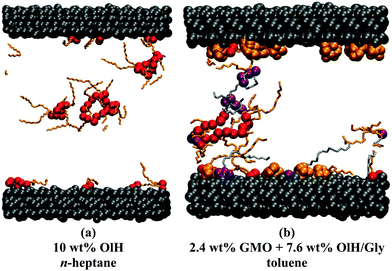
The distribution of adsorbed additives between the two surfaces is not exactly even, but this is natural given the small total numbers of molecules. In Fig. 6(b and c), the oscillations in the n-heptane mass-density profiles are less pronounced near the surfaces with stronger additive adsorption. This can be described as a ‘softening’ or ‘blurring’ of the interface between the surface and the solvent. Some interesting structures were observed in the confined fluid layers under shear, but not in bulk solutions. Fig. 7 shows some ring-like aggregates that were observed with 10 wt% OlH in n-heptane, and with 2.4 wt% GMO and 7.6 wt% OlH/Gly in toluene. These aggregates cannot be described as RMs, but there is still a high degree of structural organisation. Fig. 7(b) also shows that the Gly is strongly adsorbed on to the surface from toluene, while in n-heptane, some is still associated with the other additives in the fluid layer [Fig. 6(c)]. More snapshots from confined-fluid simulations are presented in the ESI.† The snapshots show a complex mixture of surface-adsorbed and self-assembled structures, but the ring-like aggregates shown in Fig. 7 are unusual.
The distribution of molecules in the fluid layer under shear can also be discerned from the velocity profiles, vx(z). All results are shown in Fig. 5(c and d), Fig. 8 and the ESI.† In each case, the linear velocity profile near the centre of the fluid layer is fitted with the equation
vx(z) = ![[small gamma, Greek, dot above]](https://www.rsc.org/images/entities/i_char_e0a2.gif) eff(z − z0) eff(z − z0) | (3) |
![[small gamma, Greek, dot above]](https://www.rsc.org/images/entities/i_char_e0a2.gif) eff is the effective shear rate in the centre of the fluid layer, and z0 is the position where the velocity is zero, which does not necessarily coincide with the centre of the fluid layer if there are more molecules adsorbed on one surface than the other. In the absence of any stick or slip at the solid–fluid boundary, the shear rate is simply
eff is the effective shear rate in the centre of the fluid layer, and z0 is the position where the velocity is zero, which does not necessarily coincide with the centre of the fluid layer if there are more molecules adsorbed on one surface than the other. In the absence of any stick or slip at the solid–fluid boundary, the shear rate is simply ![[small gamma, Greek, dot above]](https://www.rsc.org/images/entities/i_char_e0a2.gif) = vs/Hz. If molecules are adsorbed on to the walls, then the effective fluid-layer thickness is reduced, and
= vs/Hz. If molecules are adsorbed on to the walls, then the effective fluid-layer thickness is reduced, and ![[small gamma, Greek, dot above]](https://www.rsc.org/images/entities/i_char_e0a2.gif) eff >
eff > ![[small gamma, Greek, dot above]](https://www.rsc.org/images/entities/i_char_e0a2.gif) . The thickness of the adsorbed layer on each wall can be identified with a ‘stick length’ λ±, which is the distance between a wall at z = ±Hz/2 and the nearby position where the fitted linear velocity profile reaches ±vs/2.
. The thickness of the adsorbed layer on each wall can be identified with a ‘stick length’ λ±, which is the distance between a wall at z = ±Hz/2 and the nearby position where the fitted linear velocity profile reaches ±vs/2. | (4) |
 | (5) |
 | (6) |
![[small gamma, Greek, dot above]](https://www.rsc.org/images/entities/i_char_e0a2.gif) eff)/2. Essentially, λ gives a rough estimate of the thickness of the adsorbed layers that move with the same velocities as the walls.
eff)/2. Essentially, λ gives a rough estimate of the thickness of the adsorbed layers that move with the same velocities as the walls.
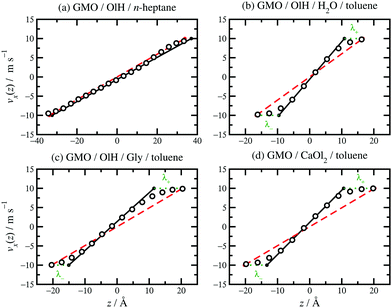 | ||
| Fig. 8 Velocity profiles for various fluids confined between parallel mica surfaces and sheared at vs = 20 m s−1: (a) 8.1 wt% GMO and 1.9 wt% OlH in n-heptane; (b) 7.8 wt% GMO, 2.1 wt% OlH, and 1.1 wt% H2O in toluene; (c) 7.4 wt% GMO and 2.6 wt% OlH/Gly in toluene; (d) 7.5 wt% GMO and 2.5 wt% CaOl2 in toluene. The MD simulation results are shown as unfilled circles, fits to eqn (3) as solid black lines, vsz/Hz as red dashed lines, and λ± as green dotted lines. | ||
Results for GMO in n-heptane and toluene sheared at 10 m s−1 were reported in ref. 13. Fig. 5(c and d) shows vx(z) for GMO in n-heptane and toluene sheared at 20 m s−1. The figures show the fitted velocity profile from eqn (3), the no-stick case vx(z) = vsz/Hz, and the values of λ±. Table 1 gives the average stick length λ, as well as the average wall separation Hz, and the fitted shear rate ![[small gamma, Greek, dot above]](https://www.rsc.org/images/entities/i_char_e0a2.gif) eff. The values of the stick lengths are in good agreement with the widths of the adsorbed-layer peaks in Fig. 5(a and b).
eff. The values of the stick lengths are in good agreement with the widths of the adsorbed-layer peaks in Fig. 5(a and b).
Some velocity profiles in mixtures are shown in Fig. 8, and the corresponding fit parameters are given in Table 1. In almost all cases, λ > 0 meaning that there are adsorbed layers on the surfaces. Exceptions include the case of GMO with a small amount of OlH in n-heptane [see Fig. 8(a)] but the magnitude of λ is so small that there is hardly any slip at the solid–fluid boundary.
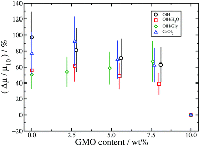
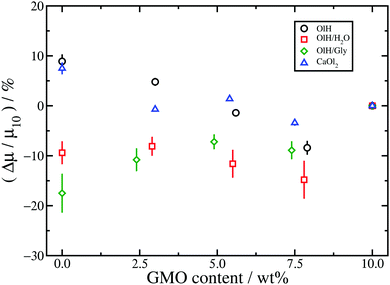
Table 1 shows the kinetic friction coefficient μ for each system, calculated with a relative wall sliding velocity of vs = 20 m s−1. In general, the friction coefficients in toluene are higher than those in the corresponding n-heptane systems, but this is mainly due to the smaller wall separation, and hence higher shear rate. In ref. 13 it was shown that for equivalent shear rates, the friction coefficients are very similar. The main focus here is on the changes in friction coefficient resulting from converting GMO in to hydrolysis products. Hence, Fig. 9 and 10 show the relative changes in μ from the system with 10 wt% GMO (μ10) in n-heptane and toluene, respectively:
 | (7) |
The results for n-heptane (Fig. 9) show that in all cases, converting GMO to other species leads to a sizeable increase in friction coefficient, and even as much as doubling the value. To some extent this is due to the fact that systems have been studied with equal numbers of additive molecules at a fixed weight percentage: replacing GMO with smaller molecules means removing some solvent molecules, which leads to a reduction in the wall separation Hz, and an increase in both the nominal shear rate ![[small gamma, Greek, dot above]](https://www.rsc.org/images/entities/i_char_e0a2.gif) and the fitted shear rate
and the fitted shear rate ![[small gamma, Greek, dot above]](https://www.rsc.org/images/entities/i_char_e0a2.gif) eff. Indeed, the kinetic friction coefficient does increase with
eff. Indeed, the kinetic friction coefficient does increase with ![[small gamma, Greek, dot above]](https://www.rsc.org/images/entities/i_char_e0a2.gif) , but the dependence is actually logarithmic and hence sub-linear.13,29,55–57 The data in Table 1 show that, in the n-heptane systems, the relative decrease in wall separation and relative increase in shear rate are much smaller than the relative increase in friction coefficient. For example, in the GMO/OlH system,
, but the dependence is actually logarithmic and hence sub-linear.13,29,55–57 The data in Table 1 show that, in the n-heptane systems, the relative decrease in wall separation and relative increase in shear rate are much smaller than the relative increase in friction coefficient. For example, in the GMO/OlH system, ![[small gamma, Greek, dot above]](https://www.rsc.org/images/entities/i_char_e0a2.gif) increases by 24% but μ increases by 97%. Note that in the GMO/OlH/Gly system, GMO is substituted by OlH and Gly which have very similar total mass, and so the wall separation and shear rate hardly change at all, but the friction coefficient still increases by 50–70%. Comparing the results for GMO/OlH and GMO/OlH/H2O in Fig. 9 shows that, in general, added water reduces the friction coefficient. This could be due to the fluidity of the surface-hydration layer described above.53,54 Roughly speaking, the results for GMO/OlH/H2O and GMO/OlH/Gly are quite similar, as are the results for GMO/OlH and GMO/CaOl2, but the error bars are quite large and make any more detailed discussion difficult.
increases by 24% but μ increases by 97%. Note that in the GMO/OlH/Gly system, GMO is substituted by OlH and Gly which have very similar total mass, and so the wall separation and shear rate hardly change at all, but the friction coefficient still increases by 50–70%. Comparing the results for GMO/OlH and GMO/OlH/H2O in Fig. 9 shows that, in general, added water reduces the friction coefficient. This could be due to the fluidity of the surface-hydration layer described above.53,54 Roughly speaking, the results for GMO/OlH/H2O and GMO/OlH/Gly are quite similar, as are the results for GMO/OlH and GMO/CaOl2, but the error bars are quite large and make any more detailed discussion difficult.
The results for toluene are shown in Fig. 10. Firstly, the changes in friction coefficient on substituting GMO are much less pronounced than in n-heptane. This is probably a consequence of there being fewer additive molecules in the toluene systems than in the n-heptane systems, and hence a lower effective surface coverage of the mica walls. Recall that the numbers of additive molecules are fixed by the number of GMO molecules required to form a RM in bulk solution. Moreover, the wall separation is much lower with toluene than with n-heptane, the separation between adsorbed and solvated additive molecules is blurred, and the extent of structural variations with different additive molecules is reduced. Secondly, while OlH and CaOl2 lead to small increases in μ, OlH/H2O and OlH/Gly lead to small decreases. Although this is very different from the situation in n-heptane, where substituting GMO always leads an increase in μ, it does indicate a general trend that OlH/H2O and OlH/Gly give lower friction coefficients than do OlH and CaOl2.
Overall, substituting GMO with OlH and another polar species such as Gly or water leads to lower friction coefficients than substituting GMO with OlH only or CaOl2. Added water probably reduces friction by forming a fluid hydrating layer at the solid–fluid interface,53,54 while the rest of the trends are correlated with the distribution of molecules between the solid–fluid interface and the middle of the fluid layer. As discussed in connection with Fig. 6, GMO/OlH/H2O has the hydration layer and GMO/OlH/Gly shows strongly adsorbed additive layers, while GMO/OlH and GMO/CaOl2 have substantial numbers of additive molecules in the centre of the fluid layer. These observations are backed up by the values of the stick lengths, λ, reported in Table 1. For example, looking at the systems with approximately 5 wt% GMO in n-heptane, the stick lengths increase in the order GMO/CaOl2 (−1.5 Å) < GMO/OlH (0.8 Å) < GMO/OlH/H2O (3.5 Å) < GMO/OlH/Gly (5.0 Å). Overall, then, friction seems to be correlated with the total polarity of the additives, and the propensity of those molecules to adsorb at the surfaces and provide an intermediate layer between the inorganic surface and the solvent.
As discussed in Section 1, there is some support for the idea that GMO (and other molecules containing ester groups) are hydrolysed to form fatty acids which are the surface-active species that lubricate surfaces,4,5 but this is by no means proven. The results presented here show that, in fact, hydrolysis products can lead to increases in the friction coefficient as compared to that of unhydrolysed GMO.
4 Conclusions
MD simulations have been used to examine self-assembly and friction in bulk and confined solutions of additives in non-aqueous solvents. The main focus was to examine how the structure and lubricating properties of the solutions change when GMO is replaced by its hydrolysis products and other species, namely OlH, Gly, and CaOl2, and when water is added. The main structural motif in the bulk solutions is a RM, which can be formed by mixtures of the additives. Under confinement and with shear applied, the distribution of molecules between the solid–fluid interface and the fluid itself varies depending on the overall polarity of the additives: mixtures of GMO, OlH, and Gly, and GMO, OlH, and water, show stronger adsorption on to the surfaces, as measured directly by mass-density profiles and from the stick lengths under Couette flow. The frictional properties are correlated with the extent of surface adsorption: while in most cases, substituting GMO with other molecules leads to an increase in friction coefficient, the increase is greater when there is less surface adsorption. Overall, this study provides a mechanism for why lubricants may degrade over time: it is possible that the hydrolysis of friction modifiers leads to the formation of species that adsorb less well on surfaces, and hence give a reduced softening or blurring of the solid–fluid interface. The results presented here are for mica surfaces, which are convenient for surface experiments (e.g., using surface force apparatus or reflectometry techniques), but not representative of the surfaces in engines. In real applications, some important differences might be anticipated. For instance, iron-oxide surfaces could be more representative of engine parts, but fatty acids may chemisorb on to such surfaces rather than physisorb. This could profoundly affect the balance between adsorption at the surface and self-assembly in the fluid. Future work should therefore address both idealised systems that can be studied in detail in experiments, and more realistic systems that capture the complexity and surface chemistry that occurs in applications.Conflicts of interest
There are no conflicts to declare.Acknowledgements
This research was supported by Infineum UK Ltd through a PhD studentship to J. L. B.-S. and funds for the purchase of computer hardware.References
- W. Hardy and I. Bircumshaw, Proc. R. Soc. London, Ser. A, 1925, 108, 1–27 CrossRef
.
- F. P. Bowden, J. N. Gregory and D. Tabor, Nature, 1945, 156, 97–101 CrossRef
.
-
F. P. Bowden and D. Tabor, The Friction and Lubrication of Solids, Oxford University Press, Revised edn, 2001 Search PubMed
.
- Z. Tang and S. Li, Curr. Opin. Solid State Mater. Sci., 2014, 18, 119–139 CrossRef
.
- J. J. Frewing, Proc. R. Soc. London, Ser. A, 1944, 182, 270–285 CrossRef
.
- I. Minami, T. Kubo, H. Nanao, S. Mori, T. Sagawa and S. Okuda, Tribol. Trans., 2007, 50, 447–487 Search PubMed
.
- K. Topolovec-Miklozic, F. Lockwood and H. Spikes, Wear, 2008, 265, 1893–1901 CrossRef
.
- L. K. Shrestha, O. Glatter and K. Aramaki, J. Phys. Chem. B, 2009, 113, 6290–6298 CrossRef PubMed
.
- L. K. Shrestha, R. G. Shrestha, M. Abe and K. Ariga, Soft Matter, 2011, 7, 10017–10024 RSC
.
- R. G. Shrestha, L. K. Shrestha, K. Ariga and M. Abe, J. Nanosci. Nanotechnol., 2011, 11, 7665–7675 CrossRef PubMed
.
- L. K. Shrestha, R. G. Shrestha, K. Aramaki, J. P. Hill and K. Ariga, Colloids Surf., A, 2012, 414, 140–150 CrossRef
.
- J. L. Bradley-Shaw, P. J. Camp, P. J. Dowding and K. Lewtas, J. Phys. Chem. B, 2015, 119, 4321–4331 CrossRef PubMed
.
- J. L. Bradley-Shaw, P. J. Camp, P. J. Dowding and K. Lewtas, Langmuir, 2016, 32, 7707–7718 CrossRef PubMed
.
- S. Murgia, F. Caboi, M. Monduzzi, H. Ljusberg-Wahren and T. Nylander, Prog. Colloid Polym. Sci., 2002, 120, 41–46 Search PubMed
.
- O. Berdeaux, S. Fontagné, E. Sémon, J. Velasco, J. L. Sébédio and C. Dobarganes, Chem. Phys. Lett., 2012, 165, 338–347 Search PubMed
.
- N. Garti and E. Avni, Colloids Surf., 1982, 4, 33–41 CrossRef
.
- J. P. Ewen, D. M. Heyes and D. Dini, Friction, 2018 DOI:10.1007/s40544-018-0207-9
.
- P. Gupta and S. Teitel, Phys. Rev. B: Condens. Matter Mater. Phys., 1997, 55, 2756–2759 CrossRef
.
- M. L. Greenfield and H. Ohtani, Tribol. Lett., 1999, 7, 137–145 CrossRef
.
- S. Bair, C. McCabe and P. T. Cummings, Phys. Rev. Lett., 2002, 88, 058302 CrossRef PubMed
.
- S. T. Cui, C. McCabe, P. T. Cummings and H. D. Cochran, J. Chem. Phys., 2003, 118, 8941–8944 CrossRef
.
- I. M. Sivebaek, V. N. Samoilov and B. N. J. Persson, Langmuir, 2010, 26, 8721–8728 CrossRef PubMed
.
- I. M. Sivebaek, V. N. Samoilov and B. N. J. Persson, Phys. Rev. Lett., 2012, 108, 036102 CrossRef PubMed
.
- X. Zheng, H. Zhu, A. K. Tieu and K. Chen, Int. J. Surf. Sci. Eng., 2014, 8, 201–212 CrossRef
.
- J. L. Rivera, G. K. Jennings and C. McCabe, J. Chem. Phys., 2012, 136, 244701 CrossRef PubMed
.
- S. M. Lundgren, M. Ruths, K. Danerlöv and K. Persson, J. Colloid Interface Sci., 2008, 326, 530–536 CrossRef PubMed
.
- M. Ruths, S. Lundgren, K. Danerlöv and K. Persson, Langmuir, 2008, 24, 1509–1516 CrossRef PubMed
.
- S. Eder, A. Vernes and G. Betz, Langmuir, 2013, 29, 13760–13772 CrossRef PubMed
.
- M. Doig, C. P. Warrens and P. J. Camp, Langmuir, 2014, 30, 186–195 CrossRef PubMed
.
- M. Doig and P. J. Camp, Phys. Chem. Chem. Phys., 2015, 17, 5248–5255 RSC
.
- J. P. Ewen, C. Gattinoni, F. M. Thakkar, N. Morgan, H. A. Spikes and D. Dini, Materials, 2016, 9, 651–667 CrossRef PubMed
.
- J. P. Ewen, S. E. Restrepo, N. Morgan and D. Dini, Tribol. Int., 2017, 107, 264–273 CrossRef
.
- Y. Morita, S. Jinno, M. Murakami, N. Hatakeyama and A. Miyamoto, Int. J. Engine Res., 2014, 15, 399–405 CrossRef
.
- J. E. Davidson, S. L. Hinchley, S. G. Harris, A. Parkin, S. Parsons and P. A. Tasker, J. Mol. Graphics Modell., 2006, 25, 495–506 CrossRef PubMed
.
- H. Berro, N. Fillot and P. Vergne, Tribol. Int., 2010, 43, 1811–1822 CrossRef
.
- T. Onodera, Y. Morita, A. Suzuki, M. Koyama, H. Tsuboi, N. Hatakeyama, A. Endou, H. Takaba, M. Kubo, F. Dassenoy, C. Minfray, L. Joly-Pottuz, J.-M. Martin and A. Miyamoto, J. Phys. Chem. B, 2009, 113, 16526–16536 CrossRef PubMed
.
- T. Onodera, Y. Morita, R. Nagumo, R. Miura, A. Suzuki, H. Tsuboi, N. Hatakeyama, A. Endou, H. Takaba, F. Dassenoy, C. Minfray, L. Joly-Pottuz, M. Kubo, J.-M. Martin and A. Miyamoto, J. Phys. Chem. B, 2010, 114, 15832–15838 CrossRef PubMed
.
- F. F. Canova, H. Matsubara, M. Mizukami, K. Kurihara and A. L. Shluger, Phys. Chem. Chem. Phys., 2014, 16, 8247–8256 RSC
.
- A. C. F. Mendonça, A. A. H. Pádua and P. Malfreyt, J. Chem. Theory Comput., 2013, 9, 1600–1610 CrossRef PubMed
.
- J. P. Ewen, C. Gattinoni, F. M. Thakkar, N. Morgan, H. A. Spikes and D. Dini, Tribol. Lett., 2016, 63, 1–15 CrossRef
.
- J. P. Ewen, C. Gattinoni, N. Morgan, H. A. Spikes and D. Dini, Langmuir, 2016, 32, 4450–4463 CrossRef PubMed
.
- LAMMPS Molecular Dynamics Simulator, http://lammps.sandia.gov.
- S. Plimpton, J. Comput. Phys., 1995, 117, 1–19 CrossRef
.
- Packmol, http://m3g.iqm.unicamp.br/packmol/home.shtml.
- L. Martínez, R. Andrade, E. G. Birgin and J. M. Martínez, J. Comput. Chem., 2009, 30, 2157–2164 CrossRef PubMed
.
- W. L. Jorgensen, D. S. Maxwell and J. Tirado-Rives, J. Am. Chem. Soc., 1996, 118, 11225–11236 CrossRef
.
- I. M. Sivebaek, V. N. Samoilov and B. N. J. Persson, J. Chem. Phys., 2003, 119, 2314–2321 CrossRef
.
- U. Tartaglino, I. M. Sivebaek, B. N. J. Persson and E. Tosatti, J. Chem. Phys., 2006, 125, 014704 CrossRef PubMed
.
- H. Heinz, H. J. Castelijns and U. W. Suter, J. Am. Chem. Soc., 2003, 125, 9500–9510 CrossRef PubMed
.
- H. Heinz and U. W. Suter, Angew. Chem., Int. Ed., 2004, 116, 2289–2293 CrossRef
.
- H. Heinz, H. Koerner, K. L. Anderson, R. A. Vaia and B. L. Farmer, Chem. Mater., 2005, 17, 5658–5669 CrossRef
.
- H. Heinz, T.-J. Lin, R. K. Mishra and F. S. Emami, Langmuir, 2013, 29, 1754–1765 CrossRef PubMed
.
- Y. S. Leng and P. T. Cummings, Phys. Rev. Lett., 2005, 94, 026101 CrossRef PubMed
.
- Y. S. Leng and P. T. Cummings, J. Chem. Phys., 2006, 125, 104701 CrossRef PubMed
.
- B. J. Briscoe and D. C. B. Evans, Proc. R. Soc. London, Ser. A, 1982, 380, 389–407 CrossRef
.
- M. R. Farrow, A. Chremos, P. J. Camp, S. G. Harris and R. F. Watts, Tribol. Lett., 2011, 42, 325–337 CrossRef
.
- S. Campen, J. Green, G. Lamb, D. Atkinson and H. Spikes, Tribol. Lett., 2012, 48, 237–248 CrossRef
.
Footnote |
| † Electronic supplementary information (ESI) available. See DOI: 10.1039/c8cp01785a |
| This journal is © the Owner Societies 2018 |

