
 Open Access Article
 This Open Access Article is licensed under a Creative Commons Attribution-Non Commercial 3.0 Unported Licence
Time-dependent changes in the growth of ultrathin ionic liquid films on Ag(111)†
Matthias
Lexow
 ,
Timo
Talwar
,
Bettina S. J.
Heller
,
Benjamin
May
,
Radha G.
Bhuin
,
Florian
Maier
and
Hans-Peter
Steinrück
*
,
Timo
Talwar
,
Bettina S. J.
Heller
,
Benjamin
May
,
Radha G.
Bhuin
,
Florian
Maier
and
Hans-Peter
Steinrück
*
Lehrstuhl für Physikalische Chemie 2, Friedrich-Alexander-Universität Erlangen-Nürnberg, Egerlandstr. 3, 91058 Erlangen, Germany. E-mail: hans-peter.steinrueck@fau.de
First published on 27th April 2018
Abstract
Various amounts of the ionic liquids (ILs) [C1C1Im][Tf2N] and [C8C1Im][Tf2N] were deposited in vacuo by physical vapour deposition (PVD) on single crystalline Ag(111) at room temperature and subsequently monitored by angle-resolved X-ray photoelectron spectroscopy (ARXPS) as a function of time. For very low coverages of up to one closed molecular layer, an initial wetting layer was rapidly formed for both ILs. Deposition of higher amounts of [C1C1Im][Tf2N] revealed an initial three-dimensional film morphology. On the time scale of hours, characteristic changes of the XPS signals were observed. These are interpreted as island spreading and a transformation towards a nearly two dimensional [C1C1Im][Tf2N] film as the final state. In contrast, a film morphology close to 2D was found from the very beginning for [C8C1Im][Tf2N] deposited on Ag(111) demonstrating the influence of the alkyl chain length on the growth kinetics. These studies also highlight the suitability of time-resolved ARXPS for the investigation of IL/solid interfaces, which play a crucial role in IL thin film applications such as in catalysis, sensor, lubrication, and coating technologies.
1. Introduction
Ionic liquids (ILs) are salts with relatively low melting points, often even below room temperature (RT). Besides numerous bulk applications using ILs as solvents, reaction media, or electrolytes, the extremely low vapour pressure of ILs has also led to the development of completely new concepts for IL thin film applications. In catalysis, thin layers of ILs on solid materials are applied e.g. in SILP (Supported Ionic Liquid Phase) and SCILL (Solid Catalyst with Ionic Liquid Layer) systems.1–3 In this context, and also from a more general point of view, the structure and composition of the IL/solid interface is of great interest in order to understand the adsorption and wetting properties of ILs on solid surfaces. While the wetting of ILs has been studied quite extensively on the macroscopic and mesoscopic scale, mostly by contact angle measurements and atomic force microscopy (for a review see ref. 4), only a few studies are available on the molecular scale. Detailed knowledge of the interface properties is, however, indispensable in order to tailor systems for specific applications, not only in catalysis, but also in other fields such as in lubrication and sensor technology.5,6 One approach for monitoring the interaction of ILs with solid surfaces is based on ultra-high vacuum (UHV) surface science methods, which allow for studying model IL systems under ultra-clean conditions with atomic level accuracy.7–10 Since 2008,11in vacuo physical vapour deposition (PVD) of ultrathin IL films combined with angle-resolved X-ray photoelectron spectroscopy (ARXPS) has proven to be a well-established method to investigate IL/solid interactions, wetting behaviour, and IL film growth in the coverage range from less than a monolayer to several multilayers.11–17 Some studies have shown ways to control the liquid/solid interface, e.g. through modification of the IL12,15,18 or the solid surface,13,19 or simply by variation of the temperature of the support.14,20 On the herringbone-reconstructed Au(111) surface, the formation of the IL/solid interface in the sub-monolayer range, and the growth mode of subsequently deposited IL multilayers at RT were studied in great detail by ARXPS for two related ILs.12,17 The first was 1,3-dimethyl imidazolium bis[(trifluoromethyl)sulfonyl]-imide ([C1C1Im][Tf2N]), that is, an IL with two methyl groups at the imidazolium cation, and the second was 1-methyl-3-octyl imidazolium bis[(trifluoromethyl)sulfonyl]-imide ([C8C1Im][Tf2N]), that is, the same IL with one octyl chain instead of one of the methyl groups; see Fig. 1. These systems serve as a reference for the adsorption on the non-reconstructed Ag(111) surface in the present study. For both ILs, the formation of a two-dimensional wetting layer (WL) is observed on Au(111) in the sub-monolayer coverage range.12 Low-temperature scanning tunnelling microscopy (STM) studies of [C8C1Im][Tf2N] and [C2C1Im][Tf2N] showed that the nucleation of stable 2D islands typically starts at the steps of the underlying reconstructed gold surface.21 Notably, even at temperatures as low as ∼90 K mobile ions are found with STM at the edges of these islands, and above ∼200 K individual molecules could not be further resolved on the STM time scale due to their high mobility.21 Hence, at RT, the WL presumably resembles a 2D liquid phase of highly mobile ions more than a stationary phase of strongly adsorbed ions. Within this WL, at low temperatures21 and at RT,12 [Tf2N]− anions and [CnC1Im]+ cations are, on average, adsorbed next to each other in an alternating arrangement, that is, in a so-called checkerboard structure. The [Tf2N]− anions are preferentially bound in a cis conformation with the polar SO2 groups pointing towards the metal surface and the CF3 groups pointing towards the vacuum, whereas the imidazolium ring of the cations is preferentially oriented parallel to the surface. In the case of [C8C1Im][Tf2N], the octyl chains initially lie horizontally on the surface to maximise the van der Waals interactions with the metal. When the WL gets close to completion, reorientation occurs with the octyl chains preferentially bending away from the surface to maximise adsorption of the polar head groups of anions and cations.12,21 For multilayer adsorption of [C1C1Im][Tf2N] and [C8C1Im][Tf2N] on Au(111), 2D layer-by-layer growth is observed, as is deduced from the attenuation characteristics of the underlying gold core level signals in ARXPS.12 Note that for multilayer coverages, no stable STM pictures could be taken even at liquid nitrogen temperature. | ||
| Fig. 1 Molecular structures of (a) 1,3-dimethyl imidazolium bis[(trifluoromethyl)sulfonyl]-imide, [C1C1Im][Tf2N], and (b) 1-methyl-3-octyl imidazolium bis[(trifluoromethyl)sulfonyl]-imide, [C8C1Im][Tf2N]. | ||
In the ARXPS experiments for ILs on Au(111) described above,12 no obvious time-dependent changes were observed. For the structurally more corrugated Au(110) surface, however, Foulston et al. recognised in time-dependent ultraviolet photoelectron spectroscopy (UPS) experiments that after depositing more than one molecular layer of [C2C1Im][Tf2N], a slow decay in the gold s-band signal intensity occurred over time.20 The authors attributed the observed behaviour to the initial formation of three-dimensional IL droplets on top of the first wetting layer, which then spread towards a more homogeneous film. It should be noted that the clean 2 × 1-reconstructed Au(110) surface undergoes a (3 × 1)-reconstruction after coating with one layer of ions, which might have an influence on the spreading mechanism.
In contrast to the situation for Au(111), the growth of ultrathin IL layers on Ag(111) as a model support for IL films at RT has been much less investigated up to now. Notably, Ag(111) does not reconstruct like Au(111) and Au(110), neither as a clean surface nor after adsorbing thin layers of [C1C1Im][Tf2N] or [C8C1Im][Tf2N]. Due to its low reactivity towards the chosen ILs, it is a good candidate for investigating IL-inherent film growth dynamics, that is, without potential structural changes of the substrate. Moreover, metallic silver is interesting, because it is a catalyst, e.g. in oxygen-assisted coupling reactions, as has been shown for Ag/Au alloys, where molecular oxygen is activated by surface silver atoms.22,23 Potential applications of these alloy systems in SCILL catalysis raise additional interest in molecular level studies of the interaction of Ag with ILs.
Low-temperature STM investigations report that sub-monolayer amounts of [C2C1Im][Tf2N] and [C8C1Im][Tf2N] exhibit a similar mobility on Ag(111) as on Au(111); only at temperatures below 200 K, condensed phases are formed and immobile ions could be observed by STM in the sub-monolayer regime. However, even below 100 K, indications of a mobile liquid 2D phase in equilibrium with the condensed phase were observed.21
In this work, the time-dependent behaviour of multilayer [C1C1Im][Tf2N] and [C8C1Im][Tf2N] films deposited on Ag(111) at room temperature will be investigated using ARXPS. It will be shown that the characteristic difference between these ILs – that is the long octyl chain substituent at the imidazolium head group – leads to very different initial film morphologies and, in the case of [C1C1Im][Tf2N], to slow changes on the time scale of hours. As final states, nearly flat films are obtained for both ILs. Our findings might be relevant for all applications where coatings of thin IL layers on solid surfaces are used.
2. Experimental
The round Ag(111) single crystal with a diameter of 15 mm and a thickness of 2 mm was purchased from MaTecK with a purity of 99.999% and one side polished and aligned to the (111) plane with an accuracy better than 0.1°. It was mounted to a Mo sample holder and fixed with a Ta wire. Surface preparation was done in UHV by sputtering with 0.6 keV Ar+ ions followed by annealing at 800 K. The sample cleanliness and long range order were checked by XPS and low energy electron diffraction (LEED), respectively. The ionic liquids [C1C1Im][Tf2N] and [C8C1Im][Tf2N] were synthesized under ultrapure conditions according to previous publications.24For our study, we used a two-chamber UHV system for preparation (sputtering, annealing, IL PVD, LEED) and analysis (ARXPS), with a base pressure of 5 × 10⁻¹¹ mbar. We deposited the defined amounts of IL onto the freshly prepared Ag(111) crystal via PVD, using a Knudsen cell.12 The cell temperatures during evaporation ranged from 380 to 430 K, at a maximum chamber background pressure of 2 × 10⁻⁹ mbar. In this temperature range, the ILs evaporate and arrive on the target surface as single ion pairs without any signs of decomposition as reported earlier in the literature.11,20,25 This behaviour was confirmed by comparing XP spectra of our deposited films to the spectra of macroscopically thick IL films prepared ex situ (see Tables S1 and S2 in the ESI†). The IL flux was checked using a quartz crystal microbalance (QCM) for each deposition experiment in order to verify the stable evaporation rates. IL deposition rates at the Ag(111) surface between 0.02 and 0.7 nm min−1 were employed. IL deposition started when the temperature of the previously annealed silver crystal was between 295 and 320 K, unless stated otherwise. Above 330 K, IL multilayer desorption effects started to occur during extended ARXPS experiments. For the study of ultrathin IL films, X-ray beam damage plays a crucial role.12 In order to avoid undesired effects due to high X-ray doses, each film for one deposition experiment was freshly prepared on a clean Ag(111) surface after completely removing the previous film by sputtering and annealing.
The XP spectra where acquired with a VG SCIENTA R3000 hemispherical electron analyser at polar emission angles of ϑ = 0° and 80° with respect to the surface normal using a non-monochromated SPECS XR 50 Al Kα X-ray source (1486.6 eV photon energy) at a power of 240 W. All spectra were measured with a pass energy of 100 eV yielding an overall energy resolution of about 0.9 eV.
Background subtraction and peak fitting was done using CasaXPS V2.3.16Dev6. The background of the Ag 3d core level was subtracted with the Shirley method.26 F 1s, O 1s and S 2p core levels were treated using a two-point linear background, C 1s with a three-point linear background. In the N 1s region, the overlap with plasmons, shake-up satellites and the inelastically scattered electrons of the Ag 3d lines made the subtraction of an additional background necessary.27–30 The N 1s spectra shown herein result from a least-squares fit of the IL N 1s peaks and the Ag 3d satellites (constrained to the parameters of the clean Ag(111) surface) followed by a subtraction of the Ag satellite contributions from the raw signal.30 For further details, see the ESI.† The IL spectra were fitted with a Voigt profile (30% Lorentzian contribution). For the C 1s spectra, a constraint of the full width at half maximum fwhm(Chet) = 1.11 × fwhm(Calk), was applied in accordance with previous studies.12,24 For the ultrathin IL films, all binding energies (BEs) reported were referenced to the silver Fermi edge, yielding a binding energy for the Ag 3d5/2 signal of 368.2 eV.
The IL film growth on Ag(111) was monitored through the changes in the Ag 3d intensity upon IL deposition. For a homogeneous 2D IL film of thickness d, the intensity of the Ag-related signal, Id, should be attenuated with respect to the intensity of the clean crystal, I0, by inelastic scattering according to:
 | (1) |
ϑ is the detection angle relative to surface normal and λ the inelastic mean free path of the electrons, which depends on the kinetic energy of the respective core level and the composition of the IL film.31 For Ag 3d electrons with a kinetic energy around 1.1 keV, a value of λ = 2.5 nm was used for the ILs [C1C1Im][Tf2N] and [C8C1Im][Tf2N]. This value was obtained by linear interpolation of values for λ of previous measurements of these and similar ILs at higher and lower kinetic energies on gold, graphene, mica, nickel, nickel oxide and silicon oxide substrates.11–13,15,32 For quantifying the attenuation of the substrate, the numerically integrated area of the Ag 3d region (Ag 3d3/2 + Ag 3d5/2 levels) between 360 and 380 eV after background subtraction was used.
For the sake of clarity, it should be noted that for ideal layer-by-layer growth (i.e., the full completion of a layer is achieved before a new layer starts to grow on top) the substrate signals should decrease in a section-wise linear fashion for each layer.12,13,33 The statistics of our data are, however, not good enough to unequivocally resolve such slope changes between adjacent straight sections. In order to detect deviations from 2D film growth, we calculated the mean film thickness d for a given deposition experiment from the experimental Id/I0 ratios at ϑ = 0°, that is, in the bulk-sensitive emission geometry, according to eqn (1).12 With the obtained d value, the expected attenuation at ϑ = 80°, that is, in the surface-sensitive emission, was then calculated using the same equation (see dashed line in Fig. 2). While the agreement between the experimental data at 80° and the calculation at 80° indicates 2D growth, Id/I0 ratios above the calculated curve indicate a 3D morphology of the IL film; such behaviour has been described for several other systems.13,15,19,32 Notably, in the present study the IL films with a 3D morphology (in particular [C1C1Im][Tf2N]) were found to change their morphology towards 2D over time, as evidenced by a change of the Id/I0 ratio after IL deposition was stopped. Therefore, all the mean IL layer thicknesses d denoted in this work were derived only after these changes levelled off, that is, when maximum attenuation of the silver signals – and thus, a sort of final state – was reached; this was typically the case between one and two hours after the IL deposition.
 | ||
| Fig. 2 Attenuation of the Ag 3d intensity in 0° and 80° emission angles as a function of the layer thickness d of the ILs [C1C1Im][Tf2N] and [C8C1Im][Tf2N] on Ag(111) at RT. The curves for 2D growth are calculated from eqn (1) with an inelastic mean free path λ of 2.5 nm and the corresponding detection angles. | ||
In accordance to previous publications, 1 ML is defined as a closed double layer of ions irrespective of their relative arrangement.11–13,15,18 The corresponding height h is estimated from the cube root of the molecular volume Vm of the respective IL
 | (2) |
Time-dependent ARXPS measurements were started immediately after the deposition of the respective IL. Because the sample needed to be transferred from the preparation chamber to the analysis chamber of our UHV system between IL deposition and XPS measurement, the first data point could only be obtained approximately 4 minutes after the end of the IL deposition. For the subsequent acquisition of spectra at 0° and 80° the sample had to be rotated between measurements. Changing the sample angle between the scans had no noticeable influence on the outcome of the time-dependent measurements. The acquisition time for the Ag 3d region was approximately 2 minutes. The time values given in the corresponding figures represent the start of each measurement.
3. Results and discussion
3.1. Growth of [C1C1Im][Tf2N] and [C8C1Im][Tf2N] on Ag(111)
Fig. 2 shows the attenuation of the Ag 3d substrate signal Id/I0 as a function of the IL film thickness after deposition of [C1C1Im][Tf2N] and [C8C1Im][Tf2N] on Ag(111) for 0° and 80° emission. The thickness values d correspond to times after deposition, when no further changes were observed (see Section 3.2); for [C1C1Im][Tf2N], this could last in some cases for more than 1 h after the end of the deposition. Both ILs exhibit similar attenuation characteristics for increasing amounts of IL deposited. As expected, the substrate signal intensity decreases with increasing film thickness. Up to 0.5 ML coverage, the measured 0° and 80° intensity ratios Id/I0 strictly coincide with the calculated values (solid and dashed lines, respectively), indicating the formation of a 2D wetting layer (WL) on Ag(111); a similar behaviour was already observed for the growth of both ILs on Au(111).12Upon further deposition on Ag(111), we find that the values for 80° are systematically larger than the calculated curve, indicating a certain degree of 3D morphology. This contrasts the situation on Au(111), where a more or less perfect 2D layer-by-layer growth was observed in the IL multilayer range. Pronounced 3D island growth on top of a WL was, however, also observed in ARXPS measurements for [C1C1Im][Tf2N] deposited on Ni(111),13 and even more pronounced, on a single graphene layer on Ni(111).32 Since on Ag(111) only small deviations from the curve for ideal 2D growth are found for both ILs, the films finally obtained are considered to be more or less flat as indicated by the right scheme shown at the bottom of Fig. 2.
In the following, the molecular arrangement within the WL on Ag(111) will be discussed in detail for both ILs. We want to emphasize that the structures and the preferential orientations discussed here should not be considered as rigid but as averaged configurations, due to the high mobility of the ions at RT. Fig. 3 shows the C 1s spectra measured at 80° for [C1C1Im][Tf2N] films of varying thickness, ranging from sub-monolayer coverage to multilayers, for a macroscopic film prepared ex situ (topmost spectrum), and for the clean Ag(111) surface (bottom spectrum). The two distinct signals Canion at ∼293 eV and Chetero at ∼287 eV correspond to the two carbon atoms in the CF3 groups of the [Tf2N]− anion and the five carbon atoms in the imidazolium cation bound to the hetero atom nitrogen, respectively. Consequently, the C 1s region allows for the simultaneous analysis of both the cations and anions. The quantitative XPS analysis of the spectra is shown in Fig. 4. Because the IL adsorbs in the form of neutral ion pairs on the surface, deviations from the expected stoichiometry have to be assigned to the arrangement and orientation of the ions. For film thicknesses below 0.5 ML, the ratios of the anionic to cationic carbon atoms are around 0.7 (similar to [C1C1Im][Tf2N] on Au(111)12), which is considerably larger than the nominal ratio of 2![[thin space (1/6-em)]](https://www.rsc.org/images/entities/char_2009.gif) :5 = 0.4. This observation is attributed to the strong damping of the cation signals due to a specific adsorption geometry: the imidazolium head groups lie parallel to the metal surface and the larger anions adsorb with a cis conformation in an upright geometry, that is, with the oxygen atoms pointing toward the surface and the CF3 groups away from the surface. In this arrangement, due to their orientation and larger size, the anions in the checkerboard structure extend, on average, farther away from the Ag surface than the cations and thus attenuate the cation signals at 80° due to inelastic scattering; see sketch in Fig. 5 (top).12 Low-temperature STM studies of similar ILs also showed this adsorption geometry of the [Tf2N]− anion on Ag(111).21 We also studied the sub-monolayer films of [C1C1Im][Tf2N] on Ag(111) by LEED (see ESI†). The absence of any super structure spots around the substrate related (1 × 1) spots confirms that, as expected, the Ag(111) surface does not undergo reconstruction upon IL deposition.
:5 = 0.4. This observation is attributed to the strong damping of the cation signals due to a specific adsorption geometry: the imidazolium head groups lie parallel to the metal surface and the larger anions adsorb with a cis conformation in an upright geometry, that is, with the oxygen atoms pointing toward the surface and the CF3 groups away from the surface. In this arrangement, due to their orientation and larger size, the anions in the checkerboard structure extend, on average, farther away from the Ag surface than the cations and thus attenuate the cation signals at 80° due to inelastic scattering; see sketch in Fig. 5 (top).12 Low-temperature STM studies of similar ILs also showed this adsorption geometry of the [Tf2N]− anion on Ag(111).21 We also studied the sub-monolayer films of [C1C1Im][Tf2N] on Ag(111) by LEED (see ESI†). The absence of any super structure spots around the substrate related (1 × 1) spots confirms that, as expected, the Ag(111) surface does not undergo reconstruction upon IL deposition.
 | ||
| Fig. 3 C 1s core level spectra in 80° emission for PVD films of [C1C1Im][Tf2N] on Ag(111) (at RT) from sub-monolayer coverages to multilayers compared to a macroscopic (thick) film. Upon completion of the wetting layer, the Chetero peak shifts by about +0.3 eV while the Canion peak shows no significant shift. | ||
 | ||
| Fig. 4 Ratio of the Canion to Chetero peak areas in the C 1s region (80° emission) as a function of the film thickness in ML of [C1C1Im][Tf2N] on Ag(111) at RT. The horizontal lines mark the nominal ratio (0.4) and the ratio observed for macroscopic (thick) films in 80° emission (0.47). The deviations for the thick film from the nominal ratio are due to a preferential surface enrichment of the CF3 groups of the anion. | ||
 | ||
| Fig. 5 Schematic of the different stages of the film growth from a checkerboard (top) for coverages <0.5 ML to a still preferentially anion enriched, but less structured multilayer vacuum interface. | ||
Above 0.5 ML, the Canion to Chetero ratio gradually decreases to a value of ∼0.47 for films thicker than 1.5 ML; see Fig. 4. This final value is also observed for macroscopic films of this IL.12,13,24,35 Apparently, above 1.5 ML the templating influence of the solid/liquid interface on the structure in the remaining IL film is overcome and a liquid/vacuum interface structure like that of the macroscopic [C1C1Im][Tf2N] films develops, as shown schematically in Fig. 5.
Next, we discuss the behaviour of the IL with the octyl chain, [C8C1Im][Tf2N], on Ag(111). Fig. 6 shows the corresponding C 1s spectra measured at 80°, along with a spectrum of the clean Ag(111) surface (bottom spectrum). In addition to the carbon signals discussed for [C1C1Im][Tf2N], we now find a third contribution at ∼285 eV, due to the seven Calkyl carbon atoms of the aliphatic side chain of the imidazolium cation; the remaining carbon atom of the octyl chain is part of the Chetero peak at 287 eV. With increasing film thickness, the ratio of the Chetero to the Calkyl peak intensities in Fig. 7 shows strong changes. At low coverages, this ratio is ∼0.65 which is close to the nominal ratio of 0.71 (=5:7). In agreement with the findings on Au(111),12 this behaviour is attributed to an adsorption geometry of the cation, where both the ring and the alkyl chain lie flat on the surface, thereby maximising the interactions with the substrate. Similar to the situation for [C1C1Im][Tf2N] on Ag(111) discussed above, the ratio of Canion to Chetero initially is ∼0.7 for the initial WL, indicating an analogous anion adsorption geometry with cis conformation, that is, with the CF3 groups pointing away from the surface. Upon completion of the WL at ∼0.5 ML, the ratio Chetero to Calkyl changes quickly to a value of about ∼0.35, which indicates a pronounced surface enrichment of the alkyl chains; this surface enrichment is even stronger than that for thick films, where a ratio of about 0.45 is observed.12,13,24,35 Again, this behaviour is similar to that described for Au(111), where the following mechanism was proposed, which should also be valid here: as the WL closes, it becomes energetically more favourable for the alkyl chains to bend away from the surface, thereby allowing additional arriving IL molecules to adsorb directly on the metal.12 Accordingly, a notable shift of the Calkyl peak of about +0.5 eV is observed between 0.3 and 0.6 ML, because the chains move further away from the silver surface and the efficiency of core hole screening decreases. A similar effect was observed on Au(111) and was attributed to a higher degree of final state screening for the chain in direct contact with the surface.12 Upon further IL deposition, the C 1s peak ratios slowly converge towards the respective values of a macroscopic film where a less strict enrichment of the alkyl chains at the IL/vacuum interface occurs.
 | ||
| Fig. 6 C 1s core level spectra in 80° emission for PVD films of [C8C1Im][Tf2N] on Ag(111) (at RT) from sub-monolayer coverages to multilayers compared to a macroscopic (thick) film. Towards the completion of the WL the Calkyl peak shifts by about +0.5 eV while the Canion peak appears to remain almost unshifted up to multilayer coverages (for details see text). | ||
 | ||
| Fig. 7 Ratios of the Chetero to Calkyl (top) and the Canion to Chetero (bottom) peak areas in the C 1s region (80° emission) as a function of the film thickness of [C8C1Im][Tf2N] on Ag(111) at RT. The horizontal lines mark the nominal ratios and the ratios observed for macroscopic films in 80° emission. The deviations of the thick films from the nominal respective ratios are due to a preferential surface enrichment of the alkyl chain of the cation (top) and the CF3 groups of the anion (bottom). | ||
3.2 Time-dependent behaviour of [C1C1Im][Tf2N] and [C8C1Im][Tf2N] on Ag(111)
After focussing mainly on the general growth behaviour and the formation of the IL/Ag(111) interface, we next address the time-dependent behaviour of the morphology of the IL films. Fig. 8 depicts representative results of the time evolution of the XP signals of [C1C1Im][Tf2N] and [C8C1Im][Tf2N] on Ag(111) at RT. The intensity ratio Id/I0 of the Ag 3d signals is plotted versus the time after ending the deposition of IL films, for nominal (that is, final) thicknesses of 1.5 (left) and 3.2 nm (right). The [C1C1Im][Tf2N] film shows a strong time-dependent behaviour. In the beginning, the Ag intensity is still rather high for both emission angles, but it then decreases substantially on the time-scale of hours before reaching a plateau. The time-dependent decrease in the substrate intensity after the end of [C1C1Im][Tf2N] deposition at RT is consistent with the findings by Foulston et al.20 for [C2C1Im][Tf2N] on Au(110). There, after initial droplet formation a slow spreading over time was observed. For times longer than 2 hours after the deposition experiment, the substrate signals tend to increase again which most likely is a result of slow desorption of the IL multilayers and perhaps some small contribution due to beam damage. The effect of beam damage on thin IL films was previously reported in detail by Cremer et al.12 Notably, Foulston et al. did not observe beam damage on ultrathin IL films in their UPS experiments, but highly destructive effects by incident electron beams during LEED and Auger electron spectroscopy.20 In reference experiments using very different X-ray exposure times, we confirmed that the observed initial time-dependent decay of the silver signals after [C1C1Im][Tf2N] deposition is not induced by the incident photon beam (see ESI†). | ||
| Fig. 8 Time-dependent ARXPS of the IL films of [C1C1Im][Tf2N] and [C8C1Im][Tf2N], respectively, after ending the IL deposition of equivalents of (a) 1.5 nm and (b) 3.2 nm on Ag(111) at RT. | ||
Unlike the situation for [C1C1Im][Tf2N], there is no time-dependent decay in the substrate intensity after the deposition of [C8C1Im][Tf2N]. The final state of the intensities in 0° and 80° are similar for both ILs indicating that the final film morphologies at this point are comparable.
The 0° emission data for nominal thicknesses of 1.5 and 3.2 nm [C1C1Im][Tf2N] in Fig. 8 show initial Id/I0 values of 0.81 and 0.78, respectively, directly after deposition, which corresponds to the apparent layer thicknesses of only ∼0.5 and 0.6 nm, respectively; this is considerably less than the mean height of an ion pair (0.73 nm). The small initial attenuation of the silver signal is in line with a configuration of high 3D IL islands (droplet) formed onto a closed wetting layer (average height: 0.37 nm), with most of the substrate signal from areas beneath the 3D islands attenuated. We cannot rule out, however, that upon deposition the 3D islands are initially formed directly on the Ag(111) surface, before the 2D WL has fully developed, and that uncovered parts of the Ag surface contribute to the XP signal. With time, the 3D islands spread to form films with a final apparent film thickness several times larger than the apparent initial value. For the 1.5 nm film (left), the increase is a factor of ∼3, and for the 3.2 nm film (right), the increase is a factor of ∼5.
Complementary time-dependent measurements were performed for the C 1s and N 1s regions after the deposition of 1.7 nm [C1C1Im][Tf2N] on Ag(111) at 300 K. They show an increase in the intensity of the IL-related peaks, which goes along with the decrease of the Ag 3d intensity; see Fig. 9. The quantitative analysis of the Chetero and Canion signals is shown in Fig. 10 as a function of time after the deposition, along with the decaying Ag signal. As also evident from Fig. 9, mainly the cationic Chetero and Ncation signals increase: within 75 min, the Chetero peak increases by ∼60%. The anionic C 1s peak also increases, but only by ∼25%. The cation and anion-related N 1s peaks show a very similar trend. The observed ratios indicate that in the initial configuration after [C1C1Im][Tf2N] deposition, the anions with their CF3 groups pointing outwards are preferentially enriched at the outer IL/vacuum interface of the IL islands. Over time, as the islands spread, the enrichment of the anions at the IL/vacuum interface decreases, which indicates that the change in island morphology also includes a change in surface composition.
 | ||
| Fig. 9 C 1s and N 1s core level spectra in 80° emission for different times after the deposition of 1.7 nm of [C1C1Im][Tf2N] on Ag(111) at RT. The nominal ratios are Canion:Chetero = 2:5 in the C 1s spectrum and Ncation:Nanion = 2:1 in the N 1s spectrum. Note how the anion signals dominate in the early stages while the expected ratios are approached only towards the end of the spreading process. | ||
 | ||
| Fig. 10 Intensities of the Chetero and Canion signals in the C 1s region from time-dependent XPS in 80° emission after the deposition of 1.7 nm of [C1C1Im][Tf2N] on Ag(111) at RT. The decay of the intensity of the Ag 3d line is shown in grey for reference. | ||
Next, we want to address the possible reasons for the time-dependent changes in the morphology of the [C1C1Im][Tf2N] films and the different behaviour observed for [C8C1Im][Tf2N]. The initial formation of comparably high 3D [C1C1Im][Tf2N] islands on-top of the closed wetting layer, and the subsequent time-dependent transformation to nearly flat films indicates the existence of two very different timescales. Upon impact, the IL ion pairs have to be very mobile on the surface, to immediately agglomerate into 3D islands. The driving force likely is the energy gain due to a much higher coordination of the individual ions in a three-dimensional structure, as compared to individual ion pairs on the WL. The formation of stable 2D [C1C1Im][Tf2N] islands on the WL from individual ion pairs obviously does not occur on the same time scale as the 3D growth; otherwise, the nearly-flat film morphology as the final state should evolve from the very beginning. We attribute this observation to the instability of the small 2D islands, which would serve as nuclei for further 2D growth. Most likely, statistically formed small 2D islands very quickly disintegrate due to the lack of stabilisation by neighbouring ions. After the end of the deposition process, we experimentally observe the slow (on the timescale of hours) transformation towards a flat morphology. This behaviour indicates that the extended regions of flat arrangements (layer-by-layer) are thermodynamically more stable than the 3D islands. The initial formation of the 3D islands is assigned to a kinetic stabilisation. Possible reasons for the slow timescale of the transformation to a 2D morphology could be a high activation barrier for the detachment/emission of an ion pair from the 3D island to the uncovered WL (or successive flat layers), or the above mentioned low probability for forming stable 2D nuclei due to the required minimum nucleus size.
The different behaviour observed for [C8C1Im][Tf2N] is attributed to a stabilisation of the IL ion pairs on the WL (or successive flat layers) by the octyl chains; it has been reported that the dispersive attractions between the alkyl chains of [C8C1Im][Tf2N] can be as large as 20% of the Coulomb interaction between the ionic components.25,36 Similar interactions are also expected with the Ag(111) substrate or the underlying wetting layer. This stabilisation could on the one hand make the initial formation of 3D islands less favourable and on the other hand lead to a higher probability for the formation of 2D islands from IL ion pairs that are emitted from the 3D islands; in addition, the octyl chain might also lead to a lower activation barrier for the detachment of IL ion pairs from the 3D islands.
As mentioned in the introduction, time-dependent changes from a 3D morphology to a 2D morphology have previously been observed by Foulston et al. for a related IL, namely [C2C1Im][Tf2N] on Au(110).20 The authors also proposed the fast initial formation of 3D islands (droplets). These droplets are kinetically controlled such that with time an activation barrier is overcome, allowing for dissociation into free ions and movement of these free ions to form layers of IL on the surface. The activation energy for this flattening process was proposed to reside in either the dissociation of the ion pairs, the movement of ions, or both.
Foulston et al. also showed that upon lowering the substrate temperature to 128 K which is well below the glass transition temperature Tg of the IL, the very limited surface diffusion leads to simultaneous multilayer growth. In this case, no initial droplet formation of [C2C1Im][Tf2N] on Au(110) could be observed.20 This behaviour could also be reproduced in the present study for the deposition of thin films of [C1C1Im][Tf2N] and [C8C1Im][Tf2N], respectively, on Ag(111) at 87 K, see Fig. 11. Also upon heating after deposition, the ILs did not show a time-dependent behaviour, which supports the above mentioned mechanism for the initial droplet formation during the deposition at RT.
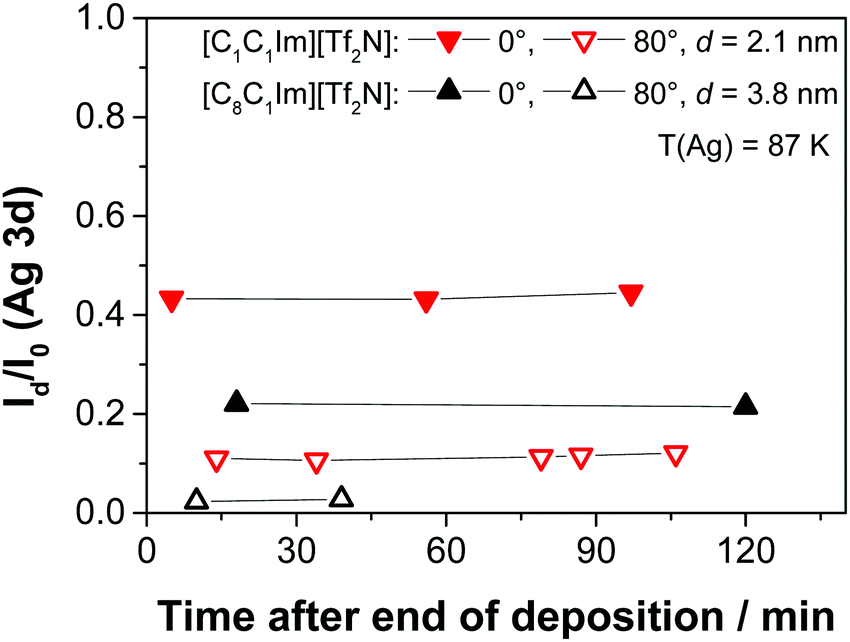 | ||
| Fig. 11 Time-dependent ARXPS of the IL films after ending the deposition of 2.1 nm of [C1C1Im][Tf2N] and 3.8 nm of [C8C1Im][Tf2N], respectively, on Ag(111) at low temperature (87 K). | ||
4. Conclusions
With the aim of understanding the fundamental aspects relevant for the application of SILP or SCILL catalysts, particularly the wetting behaviour of thin IL films, we studied the interaction of two model ILs, [C8C1Im][Tf2N] and [C1C1Im][Tf2N], with the Ag(111) surface by quantitative angle-resolved XPS on the molecular level. Upon the formation of the initial liquid/solid interface, the cations and anions adsorb in a checkerboard arrangement, that is, they form a wetting layer with both ions in contact with the Ag(111) surface. The same initial behavior was observed previously for the two ILs on the Au(111) surface.12 For higher coverages, a certain degree of 3D island growth occurs, which contrasts with the behaviour on Au(111).12 A similar growth behaviour, however, has already been reported in the literature e.g. for [C1C1Im][Tf2N] on other surfaces.13,32Upon deposition of larger amounts of IL, we find a very interesting difference for the two ILs: for [C1C1Im][Tf2N] we observe strong changes in the XP signals after the end of the deposition process on the time-scale of hours; we interpret these changes as a time-dependent change of the film morphology. For [C8C1Im][Tf2N], no such changes are found. The final film morphology appears to be very similar for the two ILs. Our detailed time-dependent measurements indicate that for [C1C1Im][Tf2N] initially large 3D IL islands (droplets) form on a very fast time scale, that is, much faster than the time needed for an XPS scan (that takes typically several minutes). These droplets then spread over time into a nearly two-dimensional film on a much slower timescale in the order of hours. The final structure is very similar to the one formed for [C8C1Im][Tf2N] from the very beginning. Time-dependent changes have previously also been found for [C2C1Im][Tf2N] on a reconstructed Au(110) surface using UV photoelectron spectroscopy.20 As a general conclusion, we propose that the observed behaviour strongly depends on the molecular structure, that is, in our case the alkyl substituents at the cationic imidazolium head group. We argue that the stabilization of the cation on the surface by van der Waals interactions of the octyl chain is responsible for the immediate formation of nearly two-dimensional films, while for imidazolium-based ILs with only methyl or ethyl groups, initially large 3D droplets are formed. The fact that the same slow IL-spreading behaviour is found for Ag(111) and for the reconstructed Au(110) surface is taken as a strong indication that a pronounced influence of the metal surface reconstruction on this process can be excluded.
Conflicts of interest
There are no conflicts to declare.Acknowledgements
We thank Nicola Taccardi for providing us with the ILs [C1C1Im][Tf2N] and [C8C1Im][Tf2N]. M. L., B. S. J. H., B. M., R. G. B., and H.-P. S. thank the European Research Council (ERC) under the European Union's Horizon 2020 research and innovation programme for financial support, in the context of the Advanced Investigator Grant “ILID” to H.-P. S. (Grant Agreement No. 693398 – ILID).References
- P. Wasserscheid and T. Welton, Ionic Liquids in Synthesis, Wiley VCH, Weinheim, 2007 Search PubMed.
- H.-P. Steinrück and P. Wasserscheid, Ionic Liquids in Catalysis, Catal. Lett., 2015, 145(1), 380–397 CrossRef.
- E. W. Castner and J. F. Wishart, Spotlight on ionic liquids, J. Chem. Phys., 2010, 132(12), 120901 CrossRef PubMed.
- I. Delcheva, J. Ralston, D. A. Beattie and M. Krasowska, Static and dynamic wetting behaviour of ionic liquids, Adv. Colloid Interface Sci., 2015, 222, 162–171 CrossRef CAS PubMed.
- F. Zhou, Y. Liang and W. Liu, Ionic liquid lubricants: designed chemistry for engineering applications, Chem. Soc. Rev., 2009, 38(9), 2590–2599 RSC.
- D. S. Silvester, Recent advances in the use of ionic liquids for electrochemical sensing, Analyst, 2011, 136(23), 4871–4882 RSC.
- E. F. Smith, I. J. Villar Garcia, D. Briggs and P. Licence, Ionic liquids in vacuo; solution-phase X-ray photoelectron spectroscopy, Chem. Commun., 2005, 5633–5635 RSC.
- E. F. Smith, F. J. M. Rutten, I. J. Villar-Garcia, D. Briggs and P. Licence, Ionic Liquids in Vacuo: Analysis of Liquid Surfaces Using Ultra-High-Vacuum Techniques, Langmuir, 2006, 22(22), 9386–9392 CrossRef CAS PubMed.
- H.-P. Steinrück, Surface science goes liquid!, Surf. Sci., 2010, 604(5–6), 481–484 CrossRef.
- H. P. Steinrück, J. Libuda, P. Wasserscheid, T. Cremer, C. Kolbeck, M. Laurin, F. Maier, M. Sobota, P. S. Schulz and M. Stark, Surface Science and Model Catalysis with Ionic Liquid-Modified Materials, Adv. Mater., 2011, 23(22–23), 2571–2587 CrossRef PubMed.
- T. Cremer, M. Killian, J. M. Gottfried, N. Paape, P. Wasserscheid, F. Maier and H. P. Steinrück, Physical Vapor Deposition of [EMIM][Tf2N]: A New Approach to the Modification of Surface Properties with Ultrathin Ionic Liquid Films, ChemPhysChem, 2008, 9(15), 2185–2190 CrossRef CAS PubMed.
- T. Cremer, M. Stark, A. Deyko, H. P. Steinrück and F. Maier, Liquid/Solid Interface of Ultrathin Ionic Liquid Films: [C1C1Im][Tf2N] and [C8C1Im][Tf2N] on Au(111), Langmuir, 2011, 27(7), 3662–3671 CrossRef CAS PubMed.
- T. Cremer, L. Wibmer, S. K. Calderon, A. Deyko, F. Maier and H. P. Steinruck, Interfaces of ionic liquids and transition metal surfaces-adsorption, growth, and thermal reactions of ultrathin [C1C1Im][Tf2N] films on metallic and oxidised Ni(111) surfaces, Phys. Chem. Chem. Phys., 2012, 14(15), 5153–5163 RSC.
- B. Uhl, T. Cremer, M. Roos, F. Maier, H.-P. Steinruck and R. J. Behm, At the ionic liquid|metal interface: structure formation and temperature dependent behavior of an ionic liquid adlayer on Au(111), Phys. Chem. Chem. Phys., 2013, 15(40), 17295–17302 RSC.
- A. Deyko, T. Cremer, F. Rietzler, S. Perkin, L. Crowhurst, T. Welton, H.-P. Steinrück and F. Maier, Interfacial Behavior of Thin Ionic Liquid Films on Mica, J. Phys. Chem. C, 2013, 117(10), 5101–5111 CAS.
- B. Uhl, F. Buchner, S. Gabler, M. Bozorgchenani and R. Jurgen Behm, Adsorption and reaction of sub-monolayer films of an ionic liquid on Cu(111), Chem. Commun., 2014, 50(62), 8601–8604 RSC.
- A. B. Biedron, E. L. Garfunkel, E. W. Castner and S. Rangan, Ionic liquid ultrathin films at the surface of Cu(100) and Au(111), J. Chem. Phys., 2017, 146(5), 054704 CrossRef PubMed.
- F. Rietzler, M. Piermaier, A. Deyko, H.-P. Steinrück and F. Maier, Electrospray Ionization Deposition of Ultrathin Ionic Liquid Films: [C8C1Im]Cl and [C8C1Im][Tf2N] on Au(111), Langmuir, 2014, 30(4), 1063–1071 CrossRef CAS PubMed.
- F. Rietzler, B. May, H. P. Steinruck and F. Maier, Switching adsorption and growth behavior of ultrathin [C2C1Im][OTf] films on Au(111) by Pd deposition, Phys. Chem. Chem. Phys., 2016, 18(36), 25143–25150 RSC.
- R. Foulston, S. Gangopadhyay, C. Chiutu, P. Moriarty and R. G. Jones, Mono- and multi-layer adsorption of an ionic liquid on Au(110), Phys. Chem. Chem. Phys., 2012, 14(17), 6054–6066 RSC.
- B. Uhl, H. Huang, D. Alwast, F. Buchner and R. J. Behm, Interaction of ionic liquids with noble metal surfaces: structure formation and stability of [OMIM][TFSA] and [EMIM][TFSA] on Au(111) and Ag(111), Phys. Chem. Chem. Phys., 2015, 17(37), 23816–23832 RSC.
- B. Xu, C. G. F. Siler, R. J. Madix and C. M. Friend, Ag/Au Mixed Sites Promote Oxidative Coupling of Methanol on the Alloy Surface, Chem. – Eur. J., 2014, 20(16), 4646–4652 CrossRef CAS PubMed.
- A. Wittstock, B. Neumann, A. Schaefer, K. Dumbuya, C. Kübel, M. M. Biener, V. Zielasek, H.-P. Steinrück, J. M. Gottfried, J. Biener, A. Hamza and M. Bäumer, Nanoporous Au: An Unsupported Pure Gold Catalyst?, J. Phys. Chem. C, 2009, 113(14), 5593–5600 CAS.
- K. R. J. Lovelock, C. Kolbeck, T. Cremer, N. Paape, P. S. Schulz, P. Wasserscheid, F. Maier and H. P. Steinrück, Influence of Different Substituents on the Surface Composition of Ionic Liquids Studied Using ARXPS, J. Phys. Chem. B, 2009, 113(9), 2854–2864 CrossRef CAS PubMed.
- J. P. Armstrong, C. Hurst, R. G. Jones, P. Licence, K. R. J. Lovelock, C. J. Satterley and I. J. Villar-Garcia, Vapourisation of ionic liquids, Phys. Chem. Chem. Phys., 2007, 9(8), 982–990 RSC.
- D. A. Shirley, High-Resolution X-Ray Photoemission Spectrum of the Valence Bands of Gold, Phys. Rev. B: Condens. Matter Mater. Phys., 1972, 5(12), 4709–4714 CrossRef.
- C. W. Bates, G. K. Wertheim and D. N. E. Buchanan, Nature of the 3.8 eV plasmon in X-ray photoemission from silver, Phys. Lett. A, 1979, 72(2), 178–180 CrossRef.
- J. Leiro, E. Minni and E. Suoninen, Study of plasmon structure in XPS spectra of silver and gold, J. Phys. F: Met. Phys., 1983, 13(1), 215 CrossRef CAS.
- N. Mårtensson, R. Nyholm and B. Johansson, New observation of two-hole core-level satellites in copper, silver, and gold, Phys. Rev. B: Condens. Matter Mater. Phys., 1984, 29(8), 4800–4802 CrossRef.
- M. Schmid, A. Kaftan, H.-P. Steinrück and J. M. Gottfried, The electronic structure of cobalt(II) phthalocyanine adsorbed on Ag(111), Surf. Sci., 2012, 606(11), 945–949 CrossRef CAS.
- M. P. Seah and W. A. Dench, Quantitative electron spectroscopy of surfaces: a standard data base for electron inelastic mean free paths in solids, Surf. Interface Anal., 1979, 1(1), 2–11 CrossRef CAS.
- F. Rietzler, J. Nagengast, H. P. Steinrück and F. Maier, Interface of Ionic Liquids and Carbon: Ultrathin [C1C1Im][Tf2N] Films on Graphite and Graphene, J. Phys. Chem. C, 2015, 119(50), 28068–28076 CAS.
- C. Argile and G. E. Rhead, Adsorbed layer and thin film growth modes monitored by Auger electron spectroscopy, Surf. Sci. Rep., 1989, 10(6), 277–356 CrossRef CAS.
- C. Kolbeck, J. Lehmann, K. R. J. Lovelock, T. Cremer, N. Paape, P. Wasserscheid, A. P. Fröba, F. Maier and H. P. Steinrück, Density and Surface Tension of Ionic Liquids, J. Phys. Chem. B, 2010, 114(51), 17025–17036 CrossRef CAS PubMed.
- F. Maier, T. Cremer, C. Kolbeck, K. R. J. Lovelock, N. Paape, P. S. Schulz, P. Wasserscheid and H. P. Steinruck, Insights into the surface composition and enrichment effects of ionic liquids and ionic liquid mixtures, Phys. Chem. Chem. Phys., 2010, 12(8), 1905–1915 RSC.
- D. H. Zaitsau, G. J. Kabo, A. A. Strechan, Y. U. Paulechka, A. Tschersich, S. P. Verevkin and A. Heintz, Experimental Vapor Pressures of 1-Alkyl-3-methylimidazolium Bis(trifluoromethylsulfonyl)imides and a Correlation Scheme for Estimation of Vaporization Enthalpies of Ionic Liquids, J. Phys. Chem. A, 2006, 110(22), 7303–7306 CrossRef CAS PubMed.
Footnote |
| † Electronic supplementary information (ESI) available. See DOI: 10.1039/c8cp01411f |
| This journal is © the Owner Societies 2018 |