
 Open Access Article
 This Open Access Article is licensed under a
 Creative Commons Attribution 3.0 Unported Licence
Atomic-scale description of interfaces in rutile/sodium silicate glass–crystal composites
Paul C. M.
Fossati
 *a,
Michael J. D.
Rushton
b and
William E.
Lee
ab
*a,
Michael J. D.
Rushton
b and
William E.
Lee
ab
aDepartment of Materials, Imperial College London, London SW7 2AZ, UK. E-mail: p.fossati@imperial.ac.uk
bNuclear Futures Institute, College of Physical and Applied Sciences, Bangor University, Bangor, Gwynedd, LL57 2UW, UK
First published on 21st June 2018
Abstract
In this work interfaces between (Na2O)x(SiO2)1−x glasses (for x = 0.0, 0.1 and 0.2) and TiO2 crystals are simulated using molecular dynamics and empirical potentials. Interfaces are presented for the distinct terminating surfaces of TiO2 with Miller indices ≤2, the properties of which have been investigated using atomistic models. Simulations showed that partially ordered layers had been induced in the glass close to the interfaces, with successive oxygen-rich and cation-rich planes being noted. The first silicate layer in contact with the crystal tended to be highly-structured, with Si ions occupying well-defined positions that depend on the orientation of the crystal at the interface, and showing 2-dimensional ordering depending on glass composition. Finally, interface energies were calculated. These indicated that the interface formation may stabilise a crystal surface in comparison to maintaining a free surface. Results are presented suggesting that the structural flexibility of the glass network allows it to conform to the crystal, thereby providing charge compensation and avoiding large relaxation of the crystal structure close to the interfaces. Such interfacial properties could be crucial to improving phenomenological models of glass–crystal composite properties.
1 Introduction
Vitrification is commonly used to immobilise high level nuclear waste (HLW) by incorporating it into a glass matrix. This method has been deployed at an industrial scale and is currently the de facto standard for HLW immobilisation in several countries such as France, the UK and the USA.1,2 During vitrification, HLW is calcined before being mixed with glass frit and then melted with the intention of forming a glass in which waste species are evenly dispersed at the atomic scale. Wasteforms resulting from vitrification, however, are often inhomogeneous and may contain secondary phases or precipitates.3–5 Some of these are refractory particles, already present in the waste stream with melting points higher than the wasteform's processing temperature, meaning that they are retained in the wasteform. Such refractory particles include ZrO2, Al2O3 or Cr2O3 crystals.4,5 Alternatively, some compounds may precipitate from the melt, such as compounds from platinoid metals6 (e.g. containing Ru, Pd, Rh) or from high oxidation state cations (e.g. Mo6+, S6+ or Cr6+). Finally, during storage, the combined effects of radiogenic heating and radiation damage may lead to de-vitrification of the wasteform with secondary crystalline phases nucleating and growing over time.7Secondary phases are diverse in terms of their structure and composition, however oxides with P42/mnm (rutile, e.g. (Ru,Rd)O2) or Fd![[3 with combining macron]](https://www.rsc.org/images/entities/char_0033_0304.gif) m structures (spinel,8e.g. (Cr,Fe,Ni)3O4) have been observed. Other phases commonly reported include molybdates and the so-called yellow phase.5,9–11 The presence of these secondary phases may have significant and deleterious effects on material performance as a wasteform. For example, yellow phase is more soluble in water than the glass matrix, providing an efficient route for radionuclides to escape the wasteform. Secondary phases can also change corrosion behaviour and overall durability of the wasteform.7
m structures (spinel,8e.g. (Cr,Fe,Ni)3O4) have been observed. Other phases commonly reported include molybdates and the so-called yellow phase.5,9–11 The presence of these secondary phases may have significant and deleterious effects on material performance as a wasteform. For example, yellow phase is more soluble in water than the glass matrix, providing an efficient route for radionuclides to escape the wasteform. Secondary phases can also change corrosion behaviour and overall durability of the wasteform.7
Some practical issues arise during processing, caused by secondary phases. For example, RuO2 crystals increase viscosity of the glass melt, which complicates its pouring into canisters by potentially obstructing the melter outlet.12 RuO2 is often collected as a “heel” at the bottom of waste canisters. For safety purposes, it is therefore important to understand the behaviour and properties of these secondary phases and the changes they cause in a wasteform's characteristics.
The purpose of this study is to improve understanding of these crystallites in vitrified wasteforms, in particular the atomic structure of the interfaces between the glass and the crystal. To this end simulations were conducted in which the structures of interfaces between TiO2 crystals and (Na2O)x(SiO2)(1−x) glasses, were predicted using Molecular Dynamics (MD) simulations. The effects of different TiO2 surface terminations are considered. In addition, the important role of Na as a glass network modifier has been examined by performing simulations with glasses where x = 0.0, 0.1 and 0.2.
2 Methods
2.1 Material: composition and interatomic potentials
In comparison to commercial vitrified waste, the glass compositions used in the simulations are relatively simple. Namely pure silica glass and two sodium silicate compositions have been studied. These have the advantage of only containing a single network forming species13 and in the case of sodium bearing glasses a single network modifier.14 It is hoped that by using such model glasses, any changes due to the presence of the glass–crystal interface will be more apparent. Separate phenomena affecting the network or modifier distribution are also more easily deconvoluted from MD derived structures for these simpler compositions, as complicating factors such as mixed alkali effects15 and multiple network formers and intermediate phases are not present.Even for the relatively simple sodium silicate systems, it is still useful to study the effect that compositional changes can have on glass–crystal interfaces. For this reason, three glasses were simulated, with 0 wt%, 10 and 20 wt% Na2O, respectively. The first was pure silica glass, which provides a useful reference system as it does not contain any network modifiers. Rutile TiO2 was chosen as the model crystal composition, as it is isostructural with platinoid oxide phases observed experimentally in nuclear wasteforms such as RuO2 and RdO2.
Molecular dynamics has been used previously to characterise other glass–crystal interfaces.16 It is an invaluable tool for such systems, as it provides both atomic-scale resolution and allows system sizes which are sufficient to simulate extended defects such as interfaces.
During MD calculations, equations of motion are solved for each atom in the simulated system. Thus, the time evolution of a structure can be predicted from a given starting point under the action of extrinsic variables such as temperature and pressure. Here, the structure and atomic trajectories at interfaces have been predicted using a simulated melt-quench approach described later in Section 2.3.
A good description of interatomic forces is essential to successful MD simulations. For this work the potential set created by Pedone et al. was used.17 This was originally developed specifically for application to glasses through empirical fits to a wide range of crystal structures. It has been validated extensively against glass compositions similar to those used here and has been shown to reproduce structural features over a broad range of sodium concentrations.17,18 For example, bond lengths,17–19 Qn distributions18,19 and non-bridging oxygen concentrations18 are all reproduced well.
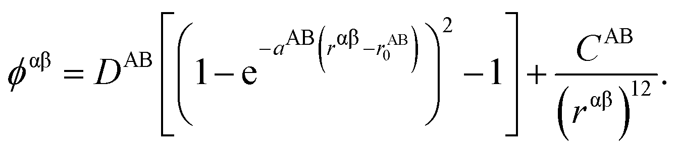
These potentials are based on a rigid ion, pair interactions model. The non-electrostatic contribution to the potential energy from a pair of ions α and β of chemical species A and B respectively is composed of a Morse term and a short-range repulsive exponential, which has the general form
| Pair | D/eV | a/Å−1 | r 0/Å | C/eV Å12 |
|---|---|---|---|---|
| Si–O | 0.340554 | 2.006700 | 2.100000 | 1 |
| Ti–O | 0.024235 | 2.254703 | 2.708943 | 1 |
| Na–O | 0.023363 | 1.763867 | 3.006315 | 5 |
| O–O | 0.042395 | 1.379316 | 3.618701 | 22 |
A short range cutoff of 12 Å was used with the potential shifted to avoid discontinuities at the cutoff. Electrostatic contributions were calculated using the Wolf sum,20 with a convergence parameter α = 0.3.
2.2 Simulated systems
The simulated configurations are layered glass/crystal composites,21 in which each phase occupies about half of the supercell. In this arrangement, the interfaces are flat and perpendicular to the z axis, which results in the sandwich structure shown in Fig. 1. Periodic boundary conditions were used for all the configurations.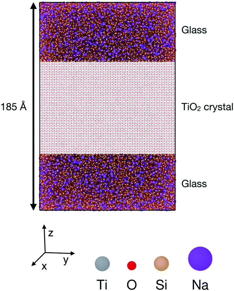 | ||
Fig. 1 Simulation setup for glass–crystal interface simulations. The middle layer is a rutile TiO2 crystal, and the other layers are (Na2O)x(SiO2)(1−x) glass. This particular example is a (100) interface. The crystal is oriented with its [010] axis along x, [00![[1 with combining macron]](https://www.rsc.org/images/entities/char_0031_0304.gif) ] along y and [100] axis along z. the glass composition is 10 wt% Na2O, the supercell is 121 × 124 × 185 Å, and contains 212 ] along y and [100] axis along z. the glass composition is 10 wt% Na2O, the supercell is 121 × 124 × 185 Å, and contains 212![[thin space (1/6-em)]](https://www.rsc.org/images/entities/char_2009.gif) 640 particles. 640 particles. | ||
As the structures and properties of crystal surfaces change depending on the orientation of the cleavage plane, it is important to consider different interfaces with various crystal terminations. Consequently, all the possible symmetrically distinct interfaces with crystallographic indices lower than 3 were studied, i.e. (001), (100), (101), (102), (110), (111), (112), (120), (121), (122), (201), and (221). The sandwich-like configuration of the simulation boxes meant that two distinct interfaces were present in each calculation, one at the top and another at the bottom of each TiO2 slab. When possible, the cleavage plane was chosen in such a way that both sides of the crystal slab were electrically neutral. For some surfaces – (111), (112), (120), (201) and (221) – there are two possibilities for the terminating plane (see Fig. 2). In these cases, the resulting interfaces were charged, one positively and one negatively, as illustrated in Fig. 2 for the (111) interfaces. Indeed, the different {111} atomic planes can contain either O and Ti, or only Ti ions. Therefore, by cleaving the crystal between two planes, there is necessarily one interface terminated by a plane that contains both cations and anions (mixed termination, with an overall negative charge), and one terminated by a cation plane (with a positive charge). Whilst such charged interfaces are unlikely to be energetically favourable, previous studies have shown that they can be stabilised under certain conditions.22 For such orientations, both positively- and negatively-charged interfaces are present in the same simulation box. The slab thickness was chosen in such a way that interface charges were screened by the bulk crystal in between and did not affect the interfaces' structure, which therefore could be analysed independently.
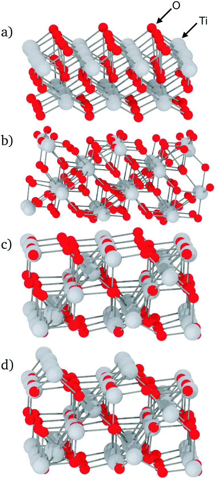 | ||
| Fig. 2 Examples of unrelaxed TiO2 surfaces: (a) (100) surface; (b) (121) surface; (c) (111) surface, mixed termination plane; (d) (111) surface, cation termination plane. In each case, the relevant interface is the top face. | ||
Cleaving the TiO2 unit cell in different orientations to obtain the required crystal surfaces results in repeat units with different shapes and sizes. This means that for each surface it was not always possible for the TiO2 slabs to have the same dimensions. Even so, to allow comparison between interfaces, care was taken to create TiO2 slabs whose dimensions along x and y were as close to 12 nm as possible, with a thickness (along z) close to 8.5 nm for all systems considered. A similar thickness was chosen for the glass phases. Checks were performed a posteriori on these simulation boxes to ensure that the system size was sufficient. To do so, separate simulations of the bulk phases were performed in similar conditions of temperature and volume as in the interface simulations. Then, the density and energy from the middle of each slab were compared to those from the bulk simulation of the same phase. No interface effect could be detected beyond about 2.0 nm for both amorphous and crystalline phases.
2.3 Interface creation
Interfaces were generated as follows. A TiO2 supercell was first created with the desired cleavage plane normal to the z-axis of the simulation box, resulting in a TiO2 slab in the middle of the simulation box bounded by empty spaces above and below. The void was filled with enough Si, O and Na atoms to give the target glass composition. The simulation box was sufficiently extended along the z-axis to provide a volume for the glass phase corresponding to the correct room-temperature glass density according to its composition:17 2.200 g cm−3, 2.294 g cm−3, and 2.385 g cm−3 for sodium concentrations of 0 wt%, 10 wt% and 20 wt% respectively. The resulting configurations were relaxed at a temperature of 5000 K for 200 ps to generate random initial positions for subsequent simulations. This was followed by a simulated quench from the molten state during which the temperature of the glass phase was decreased at 2.5 K ps−1. Temperature control for all MD runs was achieved using a Nosé–Hoover thermostat. During quenches this was set to linearly decrease the temperature of the glass component of the system from 5000 K to 300 K, therefore inducing an amorphous state which is preserved once room temperature is reached. Due to the refractory nature of TiO2, the simulation procedure was designed to mimic the solidification of glass in contact with an existing crystal surface. Consequently, during the melt quench used to form the glass, the atoms in the TiO2 slabs were held fixed to prevent any inadvertent melting of the refractory phase. Although the atoms in the crystal were fixed, forces were calculated between the crystal and the glass throughout, allowing the glass to relax in response to the crystal field. Finally, after the quench to 300 K, the constraint on the crystal was removed and a final MD equilibration was performed for 300 ps, during which both glass and crystal were allowed to relax. The validity of the glass structure generated using this process was verified by comparing the Non-Bridging Oxygen (NBO) concentration, bond lengths, and Qn distributions to reference values.18,19The GULP23 code was used to perform static energy minimisation of TiO2 cells from which interfacial systems were generated. These were subsequently used in MD simulations that were performed using the LAMMPS24 simulation package. These were run at constant volume and temperature (NVT), using a Tuckerman integration scheme,25 generating trajectories sampling a canonical ensemble.
3 Results and discussion
The interfaces considered here are flat and perpendicular to the z axis, therefore the distance from a given point in the simulation box to an interface is simply its z coordinate minus the interface position. However, the position of the interface needs to be unambiguously defined. By convention, interface position is defined as the z coordinate of the last crystalline layer. Depending on the interface, this layer can be composed of only Ti ions, only O ions, or a mixture of both.3.1 Compositional variation close to interfaces
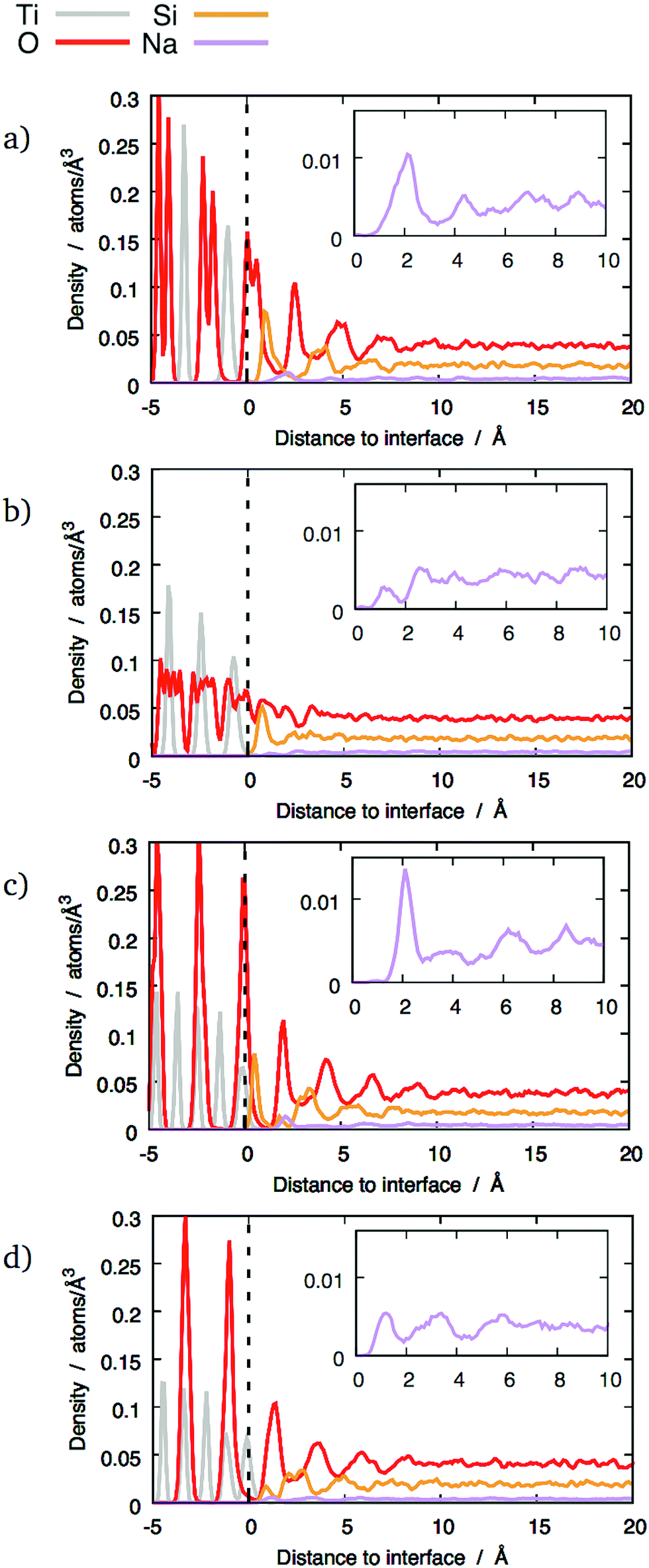
The local density of each species was calculated as a function of the distance from the interfaces. This analysis shows if segregation occurs towards or away from the interface and has been performed for each element. Furthermore, plotting density fluctuations perpendicular to the interface reveals any layer within the material, as they appear as peaks in the z-density plots. In order to obtain densities, the following method was used: the number of atoms in a series of 0.1 Å thick slices, parallel to each glass–crystal interface, were counted. A time average of the count in each slice was taken over a 300 ps MD run before being converted to a density by dividing by the volume of each slice.Fig. 3 shows the z-density plots for the systems with pure SiO2 glass. In this figure, the vertical dashed lines locate the interfaces positions as defined above, meaning that anything on its left is in the crystal and anything on its right is in the glass phase. The crystalline nature of TiO2 means that its atoms exist in clearly defined atomic planes. This is reflected in the z-densities where the TiO2 section of the plot shows distinct titanium and oxygen peaks. In the case of the (100) terminating planes these peaks show very little overlap, meaning that, in this orientation, the crystal presents as a series of alternating Ti and O layers, stacked along the z-axis, ending with an oxygen layer. An atomic visualisation of this surface is given in Fig. 2a, where the atomic layers giving rise to the density peaks can be seen clearly. A similar image is given for the (121) surface in Fig. 2b where a series of Ti layers are bounded above and below by oxygen layers. The density trace of the (121) interface (Fig. 3) shows that a combination of atomic thermal vibration and the small separation of these layer pairs have led to them merging in the (121) oxygen distribution, making them appear as squared off peaks. As would be expected, these flat-topped oxygen peaks are overlaid on to titanium peaks representing the titanium layers that the oxygen layers surround. As a result, crystal cations and anions are almost coplanar with each other at the (121) interface, allowing both Ti and O atoms to bond with the glass.
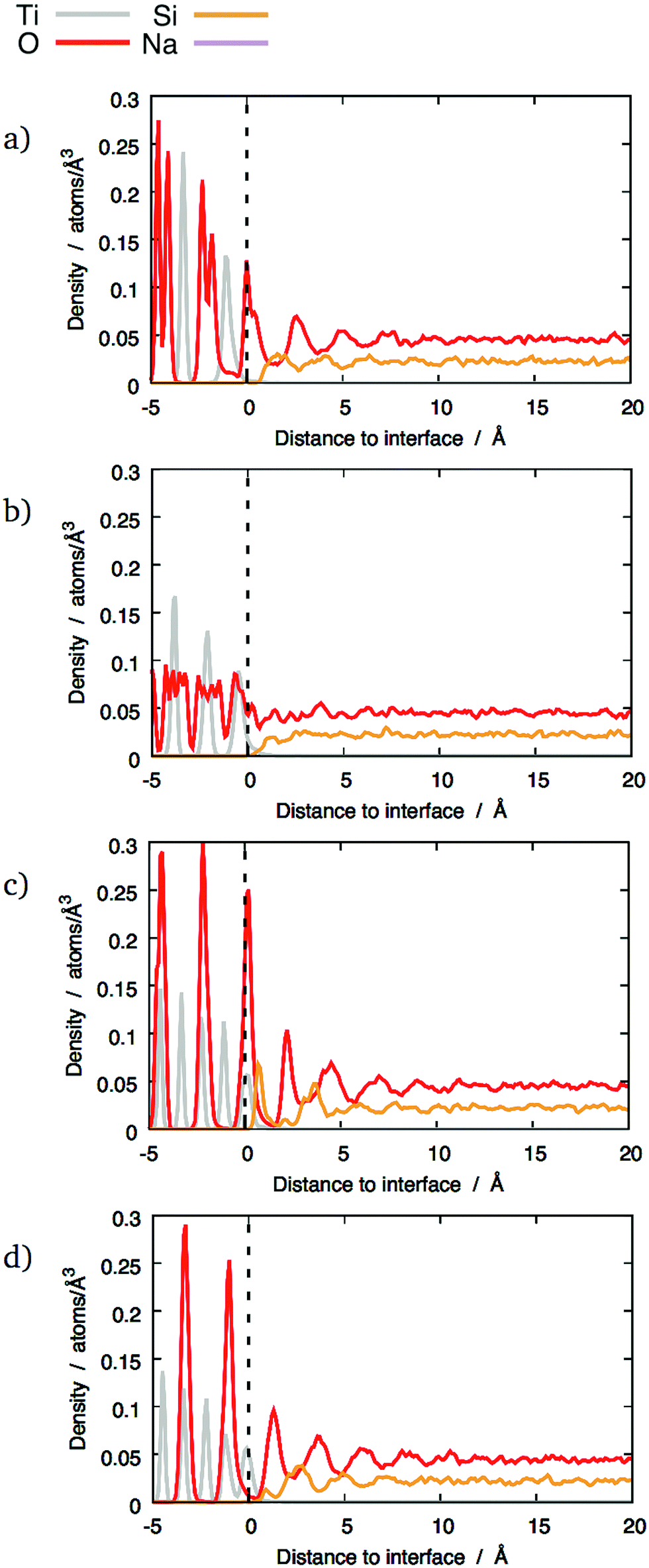 | ||
| Fig. 3 Distribution of different chemical species across some interfaces between TiO2 crystals and pure SiO2 glass: (a) (100) interface; (b) (121) interface; (c) (111) interface, mixed termination; (d) (111) interface, cation termination. The dashed lines mark the terminating crystalline planes. | ||
The final crystal orientation in Fig. 3 is (111). As discussed in Section 2.2, its termination layer can be formed of either cations or a combination of cations and anions, depending on where the crystal is cleaved. The precise atomic configuration of these surfaces are shown in Fig. 2c and d.
Generally speaking, the crystal in each interface simulation has been left relatively unperturbed by the presence of the glass at its surface. The density plots show some minor changes compared to that expected in a crystal only simulation under the same conditions, with slight broadening of the Ti and O peaks closest to the interface, indicating only small lattice distortions.
By comparison, the glass next to the interfaces has been significantly altered compared to bulk glass. If a density profile was taken along an arbitrary vector through sodium silicate glasses of the type described here, density fluctuations would be expected. The random arrangement of atoms in the glass network means that these local variations in density should also be random in nature. Bearing this in mind, the density traces for silicon and oxygen at the (100) and (111) interfaces in Fig. 3 are striking. In particular, the oxygen density shows a series of four equally-spaced peaks whose intensity diminishes away from the interface. They become indistinguishable from the fluctuations caused by the random arrangement of atoms in the glass phase at a distance between 5 and 10 Å, depending on the interface. A similar effect has been shown on interfaces between crystalline SiC and amorphous SiO2.26 This ordered pattern is not consistent with the kind of random density fluctuations expected in a typical glass. Instead, it indicates structural modification of the glass by the interface. By comparison, the (121) interfaces did not show this behaviour: instead, a single oxygen-rich layer and one cation-rich layer are visible close to the interface. This indicates that the type of interface determines how the glass structure is altered. The possible features that are present at the (100) and (111) interfaces but not at the (121) that give rise to these structural differences are discussed later.
The minima between the oxygen peaks correspond to maxima in silicon densities. This suggests that the glass contains layers, parallel to the interface that alternate between being rich in oxygen and silicon. The silicon and oxygen atoms in the glass are bound to each other as a network of corner-sharing tetrahedra, which are geometrically well defined and regular in shape. Therefore, to achieve this layer-like structure, a significant fraction of the tetrahedra must share similar orientations and must also be centred on the locations given by the silicon z-density maxima.
Previous studies of the structure of amorphous SiO2 free surfaces27,28 or nanoparticles29 have also shown the presence of different layers. Although these free surfaces exhibited a structure with an outermost oxygen-rich region, there were significant differences with the interfaces presented here. The oxygen-rich layer on the free surfaces was not as well-defined as on the glass/crystal interfaces. This was manifest in the absence of surface O peaks in the z-densities, the relative enrichment in O being caused by a decrease of Si density instead of a noticeable increase of O density. In comparison, the layers shown in Fig. 3–5 show much clearer maxima and minima, as well as several successive layers that are still noticeable at distances beyond 5 Å in the case of the (100) and mixed (111) interfaces.
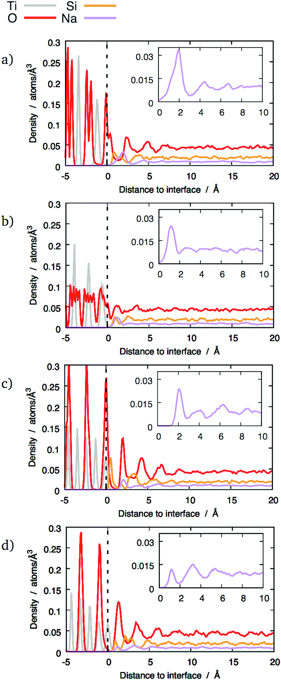
The z-densities calculated for glasses with 10 wt% and 20 wt% Na2O generally show similar behaviour to pure SiO2 glass, as shown in Fig. 4 and 5 respectively. However, the presence of sodium still has some noticeable effects. The most notable is that 10 wt% Na2O makes the Si peaks sharper and higher. Whilst it does not result in layering in interfaces that did not exhibit a layer structure with pure silica, it nonetheless caused a noticeable Si peak at the interface, as shown in Fig. 4b. In the interfaces that did exhibit layering with pure silica glass, the layers tend to be better defined after the addition of 10 wt% Na2O (Fig. 4a, c and d).
 | ||
| Fig. 4 Distribution of different chemical species across some interfaces between TiO2 crystals and 10 wt% sodium silicate glass: (a) (100) interface; (b) (121) interface; (c) (111) interface, mixed termination; (d) (111) interface, cation termination. The dashed lines mark the terminating crystalline planes. Insets show details of sodium z-densities. | ||
 | ||
| Fig. 5 Distribution of different chemical species across some interfaces between TiO2 crystals and 20 wt% sodium silicate glass: (a) (100) interface; (b) (121) interface; (c) (111) interface, mixed termination; (d) (111) interface, cation termination. The dashed lines mark the terminating crystalline planes. | ||
However, this enhanced layering was not observed with 20 wt% Na2O glass compared to 10 wt% Na2O glass. In this case, the O and Si peaks were smaller than with the other compositions. A possible explanation for this effect is discussed in Section 3.4.
3.2 Interface structure
The previous section has demonstrated that at certain interfaces, the structure of the glass has been altered even at large distances from the interface. In order to understand what gives rise to the partial order and layering of the glass away from the interface, it is important to first understand the direct interaction of the glass closest to the interface with the crystal surface. The spatial correlations induced in the glass through direct bonding of glass polyhedra to the ordered crystal may suggest a mechanism by which order may also be transmitted further into the glass, and this is now described.Using these criteria, there are three types IBOs, depending on the ions in the oxygens' first coordination shell: IBO(1) (one Ti and one Si), IBO(2) (one Ti and two Si), and IBO(3) (two Ti and one Si). These different types of interface oxygens are shown in Fig. 6. The average potential energies of the different types of oxygens have been calculated for each interface. These energies were found to be consistent across the different configurations, hence only the average energies calculated considering all the combinations of the twelve interfaces and the three glass compositions are reported in Table 2. These numbers show that it is more energetically favourable for an oxygen to be bridging than non-bridging, with oxygens in bulk TiO2 crystal having an intermediate energy. On the interfaces, the least favourable configuration is INBO, with an energy higher than NBOs in bulk glass. For the various types of IBOs, lower energies are associated with more Si neighbours, and the most favourable configuration has 2 Si and 1 Ti neighbours (IBO(2)). All the IBOs are also lower in energy than oxygen ions in TiO2 and INBO on the interface, which shows a tendency of TiO2 crystals to integrate with the silicate glass network. All the IBO configurations also have a lower potential energy than that of NBO in bulk glass.
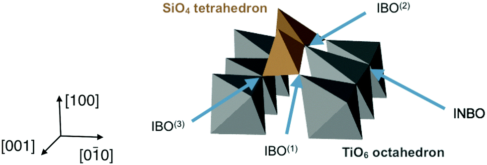 | ||
| Fig. 6 Example of Si tetrahedra on a (100) interface with glass containing 10 wt% Na2O: closeup showing the different types of interface oxygens. Only TiO6 octahedra and surface SiO4 tetrahedra are shown for clarity. | ||
| Configuration | Neighbours | Energy/eV | |
|---|---|---|---|
| Ti | Si | ||
| NBO | 0 | 1 | −7.9 ± 0.1 |
| BO | 0 | 2 | −9.9 ± 0.1 |
| O in TiO2 | 3 | 0 | −8.1 ± 0.1 |
| INBO | 2 | 0 | −7.9 ± 0.1 |
| IBO(1) | 1 | 1 | −8.9 ± 0.1 |
| IBO(2) | 1 | 2 | −10.3 ± 0.1 |
| IBO(3) | 2 | 1 | −9.5 ± 0.1 |
The populations of the different types of interface oxygens have been calculated for the different interfaces. They are reported in Table 3 for the case of SIO2 glass, normalised by the interface surface area. Whilst the precise numbers are subject to fluctuations caused by the randomness of the glass structures close to the interfaces, some significant differences between crystal orientations are visible. For example, (100) interfaces had about half as many IBOs as cation-terminated (111) interfaces (6 IBO per nm2 compared to 13 IBO per nm2). This suggests that some interfaces are more strongly bond than others, although no mechanical tests have been done in the present study to verify this. Relations between interface oxygens surface densities and layering as discussed in Section 3.1 are not easy to find, because of the difficulty of quantifying the layered character of each interface. Nonetheless, there does not seem to be any link between surface density of IBOs and layering, although INBO population is slightly lower for layered interfaces than for non-layered ones. A better metric seems to be the density of surface sites, calculated from the free surfaces of crystalline slabs surrounded by vacuum instead of glass. These combine under-coordinated oxygens and oxygens vacancies on the surfaces (where O ions would have been if the crystal extended past the surface). These can be easily calculated from unrelaxed free surfaces, without requiring a complete melt-quench process to create glass slabs. Both under-coordinated oxygens and vacancies can form IBOs when the crystal is brought into contact with glass melt. The first ones can become IBO if they bind to a Si ion, or INBO if they do not. The vacancies are favourable sites for O ions, which then also become either IBO or INBO. Thus, interfaces with large numbers of interface sites offer many possibilities for IBOs. Whilst the number of IBOs does not seem to be related to interface layering, a higher density of interface sites could offer more flexibility for the distribution of IBOs on the surface, which could help bringing ordering from the crystal into the first glass layers. The numbers reported in Table 3 show that the interfaces exhibiting stronger layering tend to also have more surface sites, although this does not necessarily translate into significantly higher IBO populations.
| Interface | IBO | IBO(1) | IBO(2) | IBO(3) | INBO | Surface sites |
|---|---|---|---|---|---|---|
| (100) | 6.2 | 3.6 | 0.3 | 2.3 | 4.6 | 14 |
| (121) | 7.4 | 4.7 | 0.6 | 2.1 | 5.1 | 12 |
| (111), mixed termination | 8.3 | 6.7 | 0.6 | 1.0 | 3.3 | 38 |
| (111), cation termination | 12.7 | 2.6 | 0.3 | 9.8 | 3.4 | 28 |
 | ||
| Fig. 7 Ordering of Si tetrahedra on glass/crystal interfaces for different (Na2O)x(SiO2)1−x glass compositions. For clarity, only the interface glass layer and the terminating crystal layer are shown. The edges indicate the O–O distances shorter than 3.5 Å as a guide showing the crystal structure. | ||
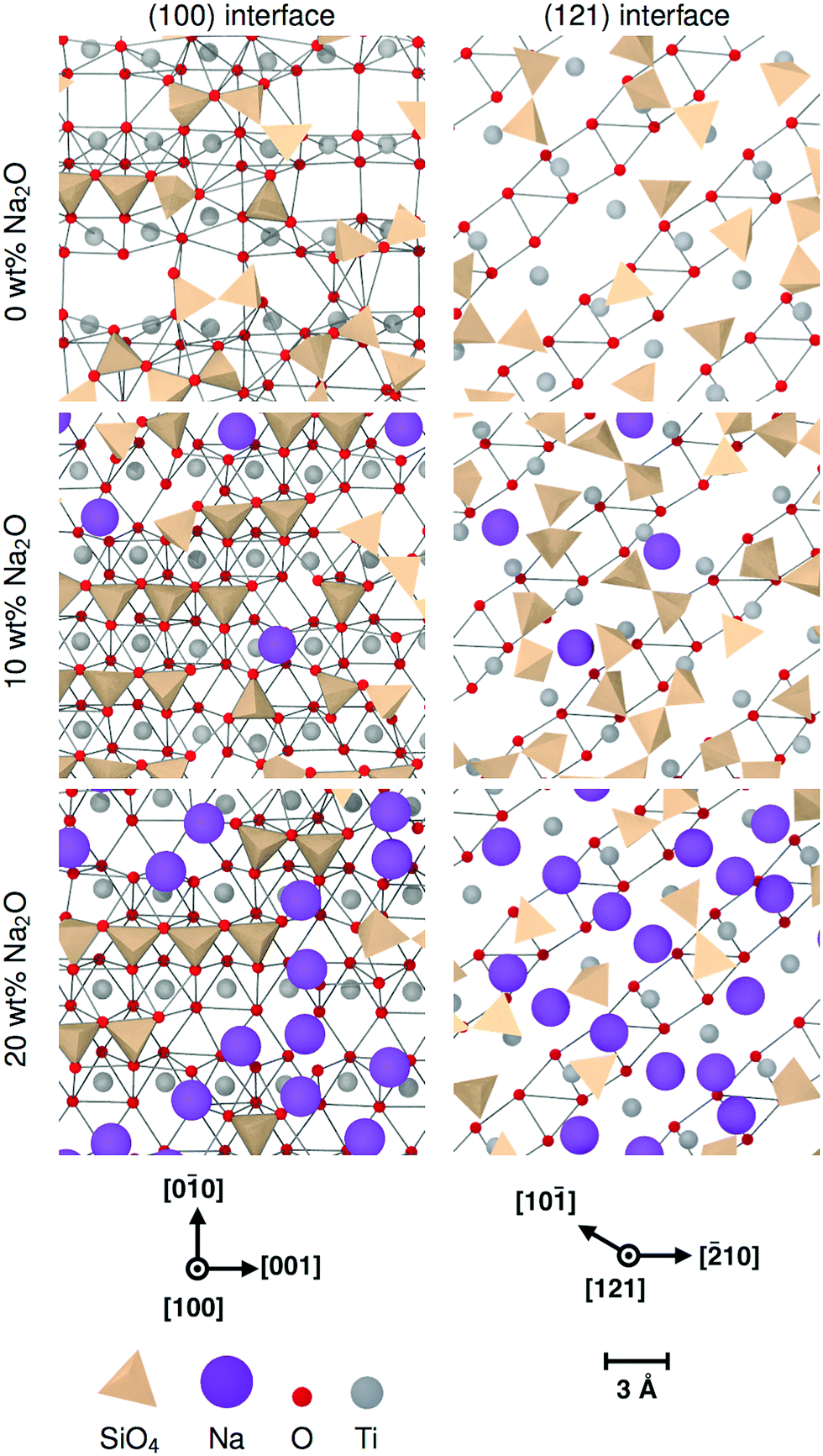
The two tetrahedra shown in Fig. 6 are examples of face-connected tetrahedra as they appear in 10 wt% Na2O glass on a (100) interface, as described previously. The figure is shown in context with TiO6 octahedra from the crystal surface. This demonstrates that the base of each tetrahedron is effectively part of the crystal, the oxygens on their corners being shared with the crystalline structure. This bonding to the crystal by the glass can account for rows of SiO4 seen in Fig. 7; the oxygen atoms in the crystal surface occupy well-defined crystallographic positions that are systematically repeated across the interface. As a consequence, by incorporating these anions into their structure, the positions of the SiO4 take on the underlying order of the crystal.
Each tetrahedron can have one, two, or three IBOs, which correspond respectively to it having a shared corner, a shared edge or a shared face with the crystal. If an interface had only corner-connected tetrahedra, its z-densities would feature a sharp O peak indicating the presence of IBOs, and then a broad Si peak and a broader O peak showing the positions of the central silicon and the oxygens forming the other corners.
The signature of face-connected tetrahedra on the z-densities would be a sharp O peak indicating the position of the connected faces, followed by a sharp Si peak and a second sharp O peak. The distance between the two O peaks should therefore be the height of a tetrahedron  , where a is the distance between two oxygens forming an edge of a SiO4 tetrahedron in the glass. Similarly, the distance between the first O peak and the first Si peak should be h = H/4, the distance between the Si at the centre of a tetrahedron and the centre of one of its faces. If the oxygen–oxygen distance in the glass is a = 2.55 Å, as has been observed on average in the glass phases, then the peak separations are respectively H = 2.08 and h = 0.52 Å. This corresponds well to the pattern observed on the z-densities for (100) interfaces, as well as the first type of (111) interface, with a mixed termination plane.
Edge-connected tetrahedra have one degree of freedom, being able to rotate around their shared edge. Thus, the two non-IBO corners can rotate in a plane perpendicular to the shared edge. The distance between these corners and the interface is not as well-defined as in the case of the face-connected tetrahedra discussed previously, and thus does not result in a clear signal on the interface density plots. In the same way, corner-connected tetrahedra can rotate along three axes, resulting in even broader density peaks. Therefore, the sharp peaks observed in the layered interfaces are to a certain extent a signature of the face-connected tetrahedra.
However, the face-connected tetrahedra alone cannot explain layering for all interfaces. Indeed, the cation-terminated (111) interface shows significant layering, although to a smaller extent as the mixed-terminated (111) interface. Despite this, its population of face-connected tetrahedra is smaller than for the (121) interface, which does not seem to show any structure beyond the first layer of glass directly in contact with the crystal. The structure of the first interface layer was further characterised by calculating the orientation of its constituent tetrahedra. To do so, for each tetrahedron, the direction closest to the axis perpendicular to the interface was selected. The orientation was then determined by calculating the angle α between this direction and the normal axis, as shown in Fig. 8a. The resulting angle distribution is shown in Fig. 8b. It shows a clear pattern for the layered interfaces – (100) and both types of (111) interfaces – for which the angle distribution has a sharper peak. For the (100) interface and (111) with mixed termination crystalline layer, this peak is for |cosα| = 1, which means that the dominant orientation is parallel to the z axis. For the cation-terminated (111) interface, the peak is for a smaller value of |cosα|, which means that the tetrahedra are not perfectly perpendicular to the interface plane. In contrast, the (121) interface have a much broader angle distribution which shows a plateau instead of a peak. Thus, interfaces showing layering are associated with a significant population of SiO4 tetrahedra aligned perpendicularly to the interface plane.
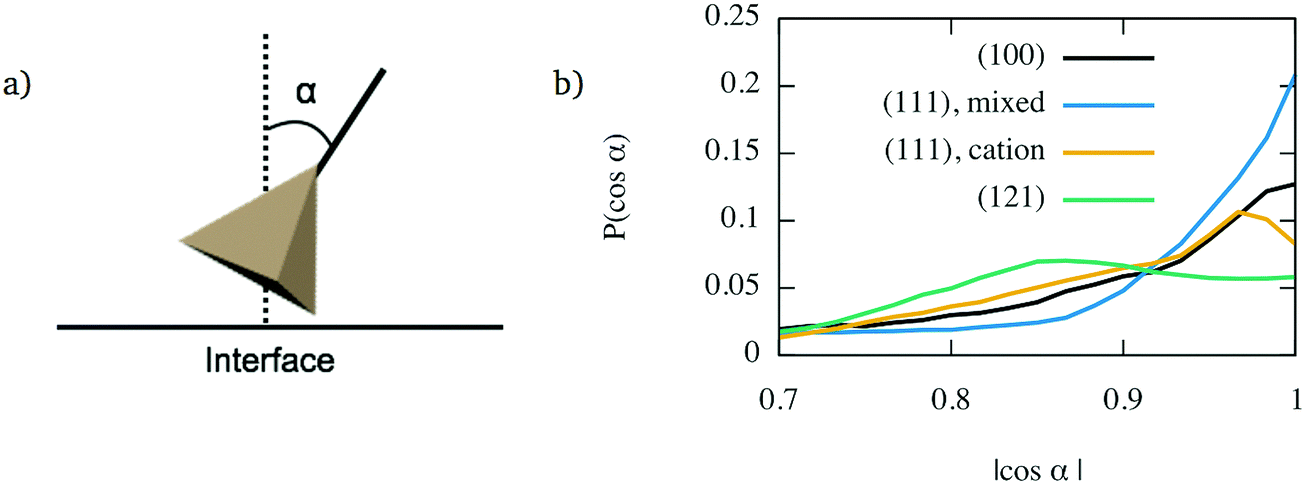 | ||
| Fig. 8 Alignment of interface tetrahedra for interfaces between TiO2 crystals and glass with (Na2O)x(SiO2)1−x 10 wt% Na2O: (a) determination of the tetrahedra orientation; (b) orientation distributions for the considered crystal orientations. | ||
3.3 Polymerisation of the glass interface layers
The degree of polymerisation of the glass network can be studied by considering the Qn speciation of Si ions, as well as populations of BOs and NBOs. The local density of each type of oxygens and silicons has been calculated in the glass phase in the same way as the z-density curves presented in Section 3.1. They are shown in Fig. 9a for the (111) interface with a mixed termination plane. Whilst no NBOs are observed close to the interfaces, their population increases with the distance from the interface, and stabilises around bulk glass values beyond about 5 Å.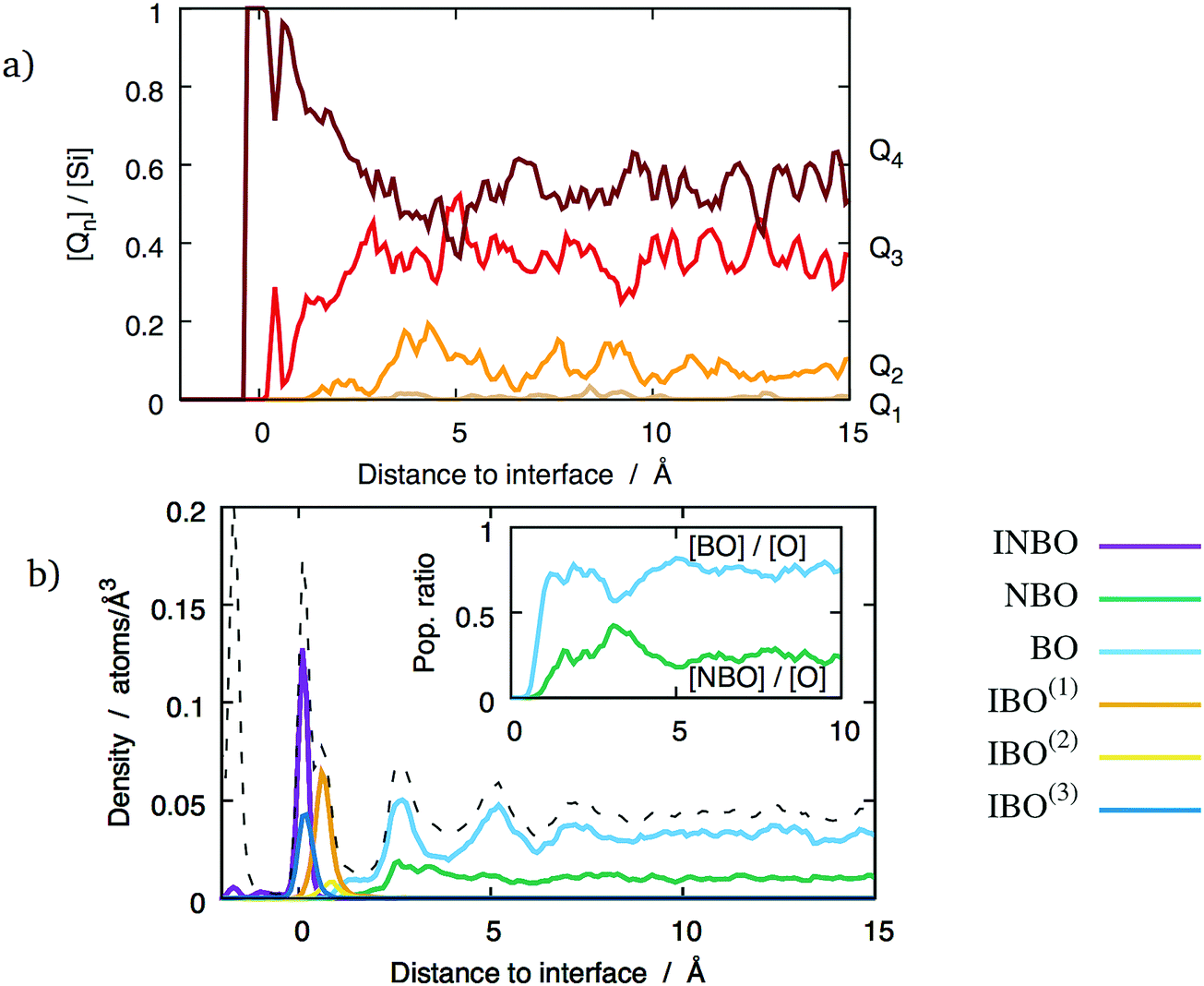 | ||
| Fig. 9 Polymerisation of (Na2O)x(SiO2)1−x glass with 20 wt% Na2O as a function of the distance to a (100) interface: (a) Qn distribution; (b) populations of the different types of oxygens (the dashed line indicates the total oxygen density). Inset in (b) shows the local fraction of NBOs and BOs in the glass phase. | ||
Considering the polymerisation of the glass network from the point of view of the silicons paints a similar picture. The proportion of Q4 tetrahedra as a function of the distance to the interface, shown in Fig. 9a, indicates that the glass phase is highly polymerised in the first 5 Å from the interface. They form the entirety of the SiO4 population in the glass contact layer. As the distance from the interface increases, the Q4 density decreases and the others, most notably Q3, increase. Beyond 5 Å, the population of each Qn type fluctuates around bulk values consistent with previous theoretical studies using the same empirical potentials18 and reasonably close to experimental values.30 These observations hold for all the considered interfaces, regardless of the orientation of the underlying crystal. The concentration of network modifiers in the glass phase changes the bulk Qn concentrations, but do not affect the high degree of polymerisation closer to the interfaces. The lack of Qn with n < 4 close to the interface might be explained by the abundance of surface oxygen vacancies. Indeed, if there is e.g. a Q3 unit, it implies the presence of one NBO. However, in the contact layer this NBO can find a vacancy to occupy, thus forming an IBO and transforming the Q3 into a Q4 tetrahedron. The direct consequence is that there are no NBOs in the contact layer, as shown in Fig. 9b. This figure shows that the proportions of BOs and NBOs stabilise at about 7 Å from the interface, where they reach their bulk values. This particular interface shows that the oxygen-poor layer between 2.5–3.5 Å is characterised by a larger proportion of NBOs, which indicates that it is less polymerised than the surrounding oxygen-rich layers. However, this does not seem to be a general feature of the considered glass/crystal interfaces. Indeed, this behaviour was only observed for the (100) interface planes, and only at high sodium concentration.
3.4 Role of network modifiers at the interface
Because of its properties as a network modifier,31 the distribution of sodium at the interface is of particular interest.Two distinct types of behaviour are apparent in the sodium z-densities. In the first case the sodium peaks closest to the interface are clearly defined, with a maximum indicating a sodium density double that in the bulk glass and followed by a clear minimum (see Fig. 4b and c). In the second case, although peaks are visible, they tend to be small and not as well-defined, with no significant enrichment (see Fig. 4a). The other interfaces exhibit distributions between these two extremes, with the first sodium peak being more or less well-defined. Overall, no longer-range sodium concentration gradient has been observed, and sodium density fluctuations are not significant beyond 7.5 Å above the interfacial reference plane, even for interfaces with the most clearly-defined layers.
Sodium does not have a large effect on the populations of different types of interface oxygens, as discussed in Section 3.2.1. Although it changes the degree of polymerisation of the bulk of the glass phases as expected by respectively reducing the concentration of Q4 and increasing that of Q3 silicons, it does not seem to affect the contact layer with the crystalline phases, which are strongly polymerised for all the tested compositions (see Section 3.3). This suggests that Na ions do not play a major role as far as charge compensation of the interface oxygens is concerned.
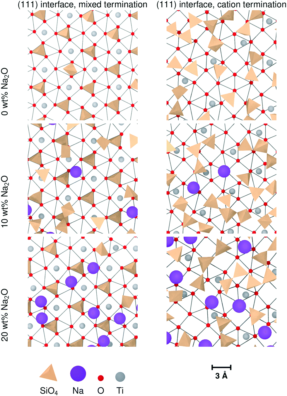
Nevertheless, sodium changes significantly the distributions of interface tetrahedra. A visible effect is that these tetrahedra tend to be more aligned in sodium-containing glasses compared to pure SiO2 glass, as can be seen in Fig. 7 and 10. This is particularly clear for interfaces showing layering, i.e. (100) and both types of (111) interfaces. Sodium also changes the way the interface tetrahedra are connected to the crystal. In general, the population of edge-connected tetrahedra decreases slightly between 0 wt% and 10 wt% Na2O, whilst the population of face-connected tetrahedra increases noticeably (see Table 4. As mentioned in Section 3.1), face-connected tetrahedra are associated with the layered glass structures found with some of the crystalline orientations. Thus, adding sodium to SiO2 glass increases layering of the glass structure by favouring face-connected tetrahedra.
| Interface | 0 wt% Na2O | 10 wt% Na2O | 20 wt% Na2O | ||||||
|---|---|---|---|---|---|---|---|---|---|
| Corner | Edge | Face | Corner | Edge | Face | Corner | Edge | Face | |
| (100) | 1.23 | 0.61 | 0.26 | 0.55 | 0.91 | 0.71 | 0.78 | 0.67 | 0.41 |
| (121) | 1.25 | 0.88 | 0.28 | 1.08 | 1.02 | 0.49 | 1.11 | 0.82 | 0.39 |
| (111), mixed | 1.23 | 0.42 | 1.49 | 1.21 | 0.36 | 1.57 | 1.35 | 0.47 | 1.49 |
| (111), cation | 1.66 | 0.76 | 0.32 | 1.27 | 0.84 | 0.48 | 1.30 | 0.83 | 0.63 |
The effect of increased sodium content beyond 10 wt% is far less clear. The z-densities, indicate a very modest increase or a decrease of the layered character of the interfaces between 10 wt% Na2O and 20 wt%. The populations of face-connected tetrahedra is also either stable or decreasing after the same composition change. Additionally, the distribution of Na ions shown in Fig. 7 indicates that they tend to occupy the same sites as SiO4 tetrahedra on the crystal interfaces. Thus, the lack of increase of ordering of the interface layers can be explained by a saturation effect, as all the sites suitable for cations are occupied either by a Na ion or a SiO4 unit. This limits the population of face-connected tetrahedra which are the major cause of layering. On most interfaces, these sites form lines along the interface, mirroring orientations with alignments of Ti cations in the crystal. As Na ions tend to preferentially occupy these sites, they form elongated clusters along the interface plane, particularly at 20 wt% Na2O.
The (111) interface where the crystal is terminated by a mixed cation/anion plane, however, has a slightly different behaviour. As can be seen in Fig. 10, the interface tetrahedra are almost perfectly ordered, even without network modifiers. Additionally, increasing sodium content from 10 wt% Na2O to 20 wt% does not change significantly the distribution of face-connected tetrahedra. Indeed, on this interface, Na ions and tetrahedra tend to occupy different locations (shown in Fig. 11), and therefore do not compete directly. This results in a highly structured interface independently of glass composition where Na ions do not tend to limit surface ordering, in contrast with the other considered interfaces. They also do not form elongated clusters, but instead are randomly distributed on their surface sites.
 | ||
| Fig. 10 Ordering of Si tetrahedra on the two types if (111) glass/crystal interfaces for different (Na2O)x(SiO2)1−x glass compositions. For clarity, only the interface glass layer and the terminating crystal layer are shown. The edges indicate the O–O distances shorter than 3.5 Å as a guide showing the crystal structure. | ||
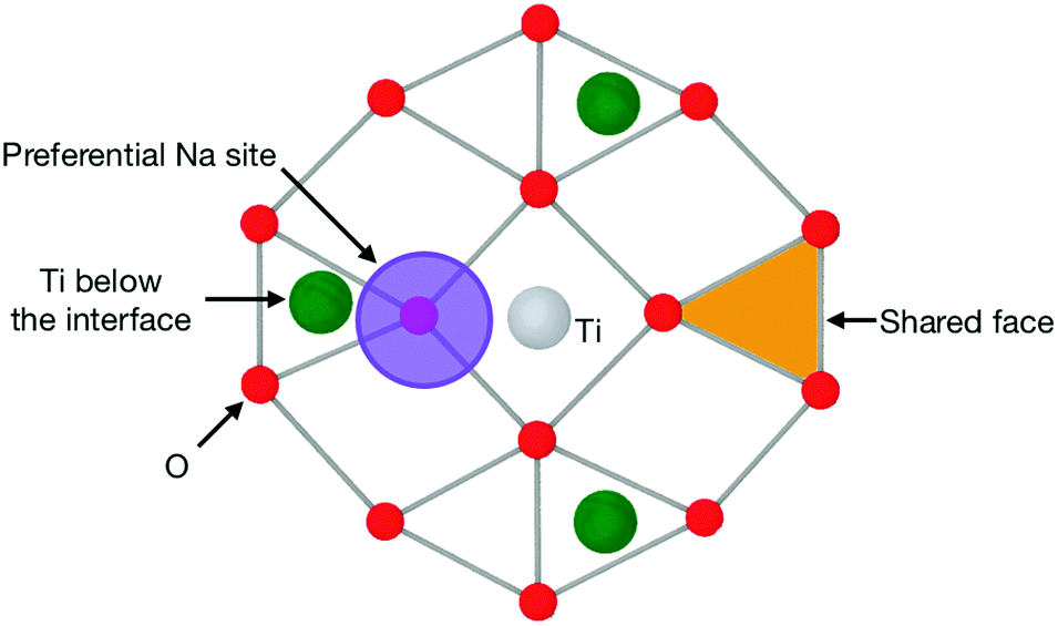 | ||
| Fig. 11 Schematic of the pattern of a (111) interface with a mixed cation/anion terminating plane, such as those shown in Fig. 10. This shows the preferential location for Na ions and the O triangle that can host a SiO4 tetrahedron, thus becoming a shared face. | ||
3.5 Interface energies
The energy of the simulated interfaces was calculated to estimate their relative stability as a function of crystal orientation and glass composition. The interface energy for a simulation box is defined as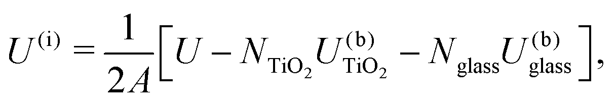 | (1) |
For the purpose of comparison, surface energies were also calculated using the same slab dimensions as for the comparable interfaces. Surface energies were calculated by performing MD calculations where the slabs were bounded by empty space rather than glass.
These surface energies are given in Table 5 and broadly show the same trend as published values from Hartree–Fock calculations,32 with the lowest-energy surface being (110), followed by (100) and (101), whilst (001) is the least favourable. However, the energies predicted by DFT calculations are consistently lower than our empirical potential results. This could partly be accounted for by the difference in simulation conditions – our results have been calculated at 300 K whilst reference values are results from static optimisation where there are no thermal vibrations to consider.
| Orientation | Free surface | Glass/crystal interface | |||
|---|---|---|---|---|---|
| This work | Ref. 32 | 0 wt% | 10 wt% | 20 wt% | |
| (001) | 2.084 | 1.32 | 0.973 | 1.128 | 1.114 |
| (100) | 1.417 | 0.76 | 0.854 | 0.733 | 0.962 |
| (101) | 1.602 | 1.08 | 1.003 | 0.988 | 1.020 |
| (102) | 1.729 | — | 0.854 | 0.829 | 0.996 |
| (110) | 1.288 | 0.54 | 0.722 | 0.760 | 0.716 |
| (111) | 2.314 | — | 0.779 | 0.888 | 0.815 |
| (112) | 1.553 | — | 0.776 | 0.847 | 0.847 |
| (120) | 1.948 | — | 0.803 | 0.768 | 0.868 |
| (121) | 1.737 | — | 0.763 | 0.794 | 0.769 |
| (122) | 1.859 | — | 0.845 | 0.976 | 0.940 |
| (201) | 2.292 | — | 0.920 | 1.035 | 1.085 |
| (221) | 1.979 | — | 0.838 | 0.949 | 0.621 |
However, the DFT reference energies are valuable as qualitative checks of the validity of the empirical potentials. Indeed, whilst the surface energies from the MD simulations are higher than the values from DFT, the relative stability of the different types of surfaces is retained. In addition, studies using variable charge potentials have shown that charge transfer occurs close to these free surfaces, which would decrease the surface energies33 compared to pair potentials such as those used in the present study. It should also be noted that other studies have found larger surface energies for the same orientations using other methods.33–35
Results shown in previous sections indicate that ions in the glass tend to arrange in cation-rich and oxygen-rich layers that are a continuation of crystal features into the glass (Section 3.1). Si ions also tend to occupy surface Ti sites and form Ti–O–Si bonds (see Section 3.2.1). In doing this, they partially compensate the charge imbalance on crystal surfaces. The consequence is that the glass/crystal interface energies are lower than the crystal surface energies for similar surface orientations. It also reduces the difference between the different interfaces. The difference between the surface with lowest and highest energies (respectively (110) and (111)) is 1.026 eV. When adding silica, the (101) surface has the highest energy, and the difference with (110) is 0.28 eV. The charge compensation role of the glass avoids large relaxations associated with higher surface energies. Changes in sodium content have very small effects on the surface energies (see Table 5), and the relative stability of the different interfaces is retained throughout the three glass compositions considered in this work.
4 Conclusions
These simulations show the strongly connected nature of the interfaces between TiO2 crystals and (Na2O)x(SiO2)1−x glass. Common structural features emerge, independent of crystal orientation and glass composition. Oxygen ions shared by both TiO6 units from the crystal and SiO4 units from the glass have a lower energy than either BOs and NBOs in the glass phase. Because of this, there is a significant number of O ions acting as bridges between the crystal lattice and the glass network (Interface Bridging Oxygens, or IBOs). The positions of these oxygens are constrained by the fact that they are bound to Ti ions from the crystal, and are therefore close to the crystalline O sites. Moreover, the Si ions of the first layer, bound to these IBOs, are mostly found close to vacant Ti sites. The consequence is that immediately on top of the interfaces are 2-dimensional SiO4 tetrahedra structures that have intermediate features between glass networks and ordered crystalline structures.These structures depend on the orientation of the underlying crystal. The structure of the first layer directly in contact with the crystal is enhanced by topological features that promote well-defined orientations for the SiO4 tetrahedra of the contact layer. The most common of these features is the presence of O triangles on the surface that can be integrated as faces of SiO4 tetrahedra shared with the crystal, which is the main cause of ordering on (111) interfaces with mixed termination planes. A strongly ordered contact layer in turn constrains the glass network immediately above it, which can result in a second partially-ordered layer, depending on the orientation of the underlying crystal. This has been observed for (100) and (111) interfaces, in some cases with a visible third layer.
Increasing sodium content does not significantly change the number of interface Si ions, or their tendency to occupy vacant Ti sites. It does, however, change their two-dimensional distribution on the interface planes. A common feature of interface structures with high sodium content is the formation of elongated clusters of Na ions on the interface plane. This feature could have an important effect on ionic transport properties and mechanical strength of these interfaces and potentially on the durability of a wasteform containing it.
The simulations presented here focused on the structure of the interface. Nevertheless, they offer insight into how these interface structures could emerge during glass processing. As the crystal phase retains its structure whilst immersed in the glass melt, the topology of its interfaces induces preferential adsorption sites for mobile ions, resulting in a partially ordered contact layer. This partial order can be characterised by preferences in the distribution of SiO4 tetrahedra and Na ions on the interface, as well as by the orientation of the tetrahedra. Whilst they may be able to connect to the crystal lattice, they cannot reproduce the three-dimensional crystal structure. They can, however, have preferred orientations that offer a second layer of favourable sites for the ions in the melt, thus allowing the limited propagation of the structure into the melt. During the quenching process, the ions can move to accommodate large local stresses, but not enough to drastically change the structure of the interface layers. This results in the features described previously in the final glass composite material at room temperature.
Conflicts of interest
There are no conflicts of interest to declare.Acknowledgements
The simulations used the Imperial College HPC clusters, as well as computational resources of the Materials Modelling Hub, which is partly funded by EPSRC (EP/P020194/1). This work used the ARCHER UK National Supercomputing Service (http://www.archer.ac.uk). This project is funded by the DISTINCTIVE consortium under the EPSRC grant EP/2014041/1. Pictures were generated using Ovito.36References
- I. W. Donald, B. L. Metcalfe and R. N. J. Taylor, J. Mater. Sci., 1997, 32, 5851–5887 CrossRef.
- J. D. Vienna, Int. J. Appl. Glass Sci., 2010, 1, 309–321 CrossRef.
- M. I. Ojovan and W. E. Lee, An introduction to nuclear waste immobilisation, Elsevier, Oxford, 2nd edn, 2014 Search PubMed.
- W. E. Lee, M. I. Ojovan, M. C. Stennett and N. C. Hyatt, Adv. Appl. Ceram., 2013, 105, 3–12 CrossRef.
- P. B. Rose, D. I. Woodward, M. I. Ojovan, N. C. Hyatt and W. E. Lee, J. Non-Cryst. Solids, 2011, 357, 2989–3001 CrossRef.
- D. F. Bickford and M. E. Smith, The behavior and effects of the noble metals in the DWPF melter system (U), Westinghouse Savannah River Company, 1997 Search PubMed.
- B. Grambow, Elements, 2007, 2, 357–364 CrossRef.
- J. Alton, T. J. Plaisted and P. Hrma, J. Non-Cryst. Solids, 2002, 311, 24–35 CrossRef.
- P. B. Rose, PhD thesis, The University of Sheffield, 2008.
- R. Short, Procedia Mater. Sci., 2014, 7, 93–100 CrossRef.
- S. K. Sundaram and J. M. Perez Jr., Noble metals and spinel settling in High Level Waste glass melters, Pacific northwest national laboratories technical report, 2000.
- J. Puig, B. Penelon, P. Marchal and M. Neyret, Procedia Mater. Sci., 2014, 7, 156–162 CrossRef.
- W. H. Zachariasen, J. Am. Chem. Soc., 1932, 54, 3841–3851 CrossRef.
- G. N. Greaves, J. Non-Cryst. Solids, 1985, 71, 203–217 CrossRef.
- J. O. Isard, J. Non-Cryst. Solids, 1969, 1, 235–261 CrossRef.
- M. J. D. Rushton, PhD thesis, Imperial College London, 2006.
- A. Pedone, G. Malavasi, M. C. Menziani, A. N. Cormack and U. Segre, J. Phys. Chem. B, 2006, 110, 11780–11795 CrossRef PubMed.
- L. Adkins and A. N. Cormack, J. Non-Cryst. Solids, 2011, 357, 2538–2541 CrossRef.
- A. Pedone, G. Malavasi, A. N. Cormack, U. Segre and M. C. Menziani, Chem. Mater., 2007, 19, 3144–3154 CrossRef.
- D. Wolf, P. Keblinski, S. R. Phillpot and J. Eggebrecht, J. Chem. Phys., 1999, 110, 8254–8282 CrossRef.
- M. J. D. Rushton, R. W. Grimes and S. L. Owens, J. Am. Ceram. Soc., 2008, 91, 1659–1664 CrossRef.
- X. Liu, H. Zhang, X. Yao, T. An, P. Liu, Y. Wang, F. Peng, A. R. Carroll and H. Zhao, Nano Res., 2012, 5, 762–769 CrossRef.
- J. D. Gale and A. L. Rohl, Mol. Simul., 2003, 29, 291–341 CrossRef.
- S. J. Plimpton, J. Comput. Phys., 1995, 117, 1–19 CrossRef.
- M. E. Tuckerman, J. Alejandre, R. López-Rendón, A. L. Jochim and G. J. Martyna, J. Phys. A: Math. Gen., 2006, 39, 5629–5651 CrossRef.
- A. Miyashita, T. Ohnuma, M. Iwasawa, T. Sakai, T. Kano, M. Yoshikawa and N. Soneda, First-Principles Molecular Dynamics Simulation of Oxide Layer for SiC Devices, Annual report of the earth simulator center technical report, 2007.
- S. H. Garofalini, J. Chem. Phys., 1983, 78, 2069–2072 CrossRef.
- M. Rarivomanantsoa, P. Jund and R. Jullien, J. Phys.: Condens. Matter, 2001, 13, 6707–6718 CrossRef.
- A. Roder, W. Kob and K. Binder, J. Chem. Phys., 2001, 114, 7602–7614 CrossRef.
- H. Maekawa, T. Maekawa, K. Kawamura and T. Yokokawa, J. Non-Cryst. Solids, 1991, 127, 53–64 CrossRef.
- G. N. Greaves, W. Smith, E. Giulotto and E. Pantos, J. Non-Cryst. Solids, 1997, 222, 13–24 CrossRef.
- H. Perron, C. Domain, J. Roques, R. Drot, E. Simoni and H. Catalette, Theor. Chem. Acc., 2007, 117, 565–574 Search PubMed.
- V. Swamy, J. Muscat, J. D. Gale and N. M. Harrison, Surf. Sci., 2002, 504, 115–124 CrossRef.
- J. Muscat, N. M. Harrison and G. Thornton, Phys. Rev. B: Condens. Matter Mater. Phys., 1999, 59, 2320–2326 CrossRef.
- J. Muscat and N. M. Harrison, Surf. Sci., 2000, 446, 119–127 CrossRef.
- A. Stukowski, Modell. Simul. Mater. Sci. Eng., 2010, 18, 015012 CrossRef.
| This journal is © the Owner Societies 2018 |