The next generation vanadium flow batteries with high power density – a perspective
Wenjing
Lu
ab,
Xianfeng
Li
 *ac and
Huamin
Zhang
 *ac
*ac
aDivision of energy storage, Dalian Institute of Chemical Physics, Chinese Academy of Sciences, Zhongshan Road 457, Dalian 116023, China. E-mail: lixianfeng@dicp.ac.cn; zhanghm@dicp.ac.cn
bUniversity of Chinese Academy of Sciences, Beijing 100049, China
cCollaborative Innovation Centre of Chemistry for Energy Materials (iChEM), Dalian 116023, China
First published on 6th December 2017
Abstract
Vanadium flow batteries (VFBs) have received increasing attention due to their attractive features for large-scale energy storage applications. However, the relatively high cost and severe polarization of VFB energy storage systems at high current densities restrict their utilization in practical industrial applications. Optimization of the performance of key VFB materials, including electrodes, electrolytes and membranes, can realize simultaneous minimization of polarization and capacity decay. The power density and energy density of VFBs are thus simultaneously enhanced. Moreover, relevant theoretical mechanisms and foundations based on virtual investigations of VFB models and simulations can guide these optimizations. The improved power density and energy density can reduce the cost of VFB energy storage systems, accelerating their successful industrialization. In this perspective, modification methods to optimize the performance of key VFB materials and investigations of models and simulations of VFBs will be discussed. Therefore, the available ideas and approaches will be provided to direct further improvements in the power density and energy density of VFB systems.
1. Introduction
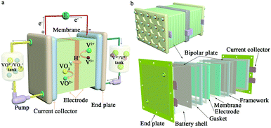
Due to the continual increase in concerns regarding global environmental pollution and the energy crisis, it is increasingly urgent to propel the development and utilization of renewable energy sources. However, renewable energy sources, such as solar and wind power, possess the undesirable features of high intermittence and instability. It is very difficult to realize reasonable and efficient use of renewable energy sources when generating electricity.1,2 At this time, large-scale energy storage technologies have begun to play an important role in ensuring a safe and reliable power supply.1 Large-scale energy storage technologies can store inconsecutive electrical energy generated from renewable energy sources and release continuous electricity, thus effectively tuning the instability and discontinuity of renewable energy sources. Therefore, large-scale energy storage technology is key in converting the role of renewable energy sources from auxiliary to dominant.3,4Among various large-scale energy storage technologies, such as pumped hydro storage, compressed air energy storage and battery energy storage, vanadium flow batteries (VFBs) possess the outstanding characteristics of high safety, large output power and storage capacity, rapid response, long cycle life, high efficiency, and environmental benignity.4–10 A VFB employs vanadium ions with different valences as active species in different half-cell electrolytes to store electrical energy converted from chemical energy. The positive electrolyte uses the VO2+/VO2+ redox couple, while the V2+/V3+ redox couple is utilized in the negative electrolyte. Using the same element in different half-cell electrolytes can effectively ameliorate the cross-mixing of active species so as to diminish self-discharge and capacity loss. Moreover, electrolytes can be reused to reduce the system cost. The electrochemical reactions occurring on the surfaces of the electrodes during the charge–discharge process can be expressed as follows:11–13
Cathode:
Anode:
Overall electrochemical reaction:
The development of VFBs has been very rapid, and many significant achievements have been realized. To date, many VFB demonstration programs have already been realized, including a 5 MW/10 MW h commercial demonstration system in China and a 15 MW/60 MW h system in Japan.14,15 Therefore, VFBs are the most promising technology for the application of large-scale energy storage at present. The successful industrial application of VFB energy storage systems will very probably be accomplished in the near future. However, the comparably high cost of VFBs seriously restricts their further development.16,17 In addition, the low solubility and poor stability of vanadium ions in supporting electrolytes impose a major restriction on the energy density of VFB systems.11,16,18 Additionally, the increased current density contributes to more severe polarization, which significantly reduces the power density of VFB systems. The energy efficiency, which acts as the indicator of the energy conversion ratio in the charge–discharge process, will decrease accordingly. Moreover, the conductivity of membranes at high current densities also affects the power density of VFB systems to a large extent.19–21
In recent years, with the intent of improving the power density and energy density of VFB systems, many investigations concentrating on key VFB materials have been carried out. For example, detecting surface treatments on electrodes to decrease electrochemical polarization, introducing additives as precipitation inhibitors in electrolytes to improve the vanadium-ion concentration and thermal stability, carrying out structure design and optimization to improve the selectivity and conductivity of membranes, and designing more accurate and effectual system models and simulations are available methods to increase the power density and energy density of VFB systems. This perspective will focus on the most recent achievements of these investigations and describe the developing future trends of VFB electrodes, electrolytes and membranes. Additionally, studies of models and simulations of VFB systems will be reviewed. Therefore, this perspective will provide effective ideas and methods to direct further improvements in the power density and energy density of VFB systems.
2. Strategies for improving the power density and energy density of VFB systems
2.1 Electrode
Types of battery polarization include electrochemical or active polarization, ohmic polarization and concentration polarization. These polarization phenomena are strongly affected by the chemistry of the electrodes, the resistance of the electrolytes, the performance of the membranes, etc., especially for electrochemical polarization.20–23 The dominant source of overpotential in each region of a generalized polarization curve for a VFB is shown in Fig. 2.24 The electrode surface is the place where the redox reactions occur. Therefore, investigations on electrodes are extremely significant for improving the power density of VFB systems.20 A perfect electrode applied in VFBs should possess high electrochemical activity and reversibility, high conductivity, low resistance for mass transfer, excellent mechanical, thermal and chemical stability, and low cost.20,25,26 Carbon materials, particularly carbon felt and graphite felt, are currently the most commonly used electrode materials.20,25,26 Their eminent three-dimensional porous structures with high specific areas can provide continuous and unhindered passage for the electrolyte, promoting mass transfer and minimizing the concentration polarization. The high specific area provides more active reaction sites for the redox couples, thus improving the electrochemical activity and reaction kinetics. The high conductivity can efficiently decrease the ohmic polarization. Furthermore, the high mechanical, thermal and chemical stability ensure maintenance of stable battery performance under the strongly oxidizing and acidic VFB operating conditions.19 In the following section, this paper will concentrate on the modification methods of carbonaceous materials.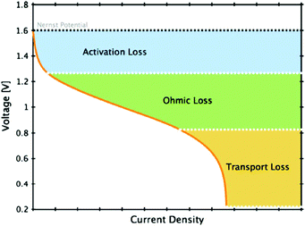 | ||
| Fig. 2 Generalized polarization curve for a VFB, indicating the dominant source of overpotential in each region.24 Reprinted with permission from ref. 24. Copyright Springer, 2011. | ||
Wang et al. used bismuth (Bi) as the electrocatalyst on the surface of a graphite felt electrode.21 Cleverly, they utilized electrolytes containing Bi3+. Bi metal could thus be synchronously electrodeposited on the negative electrode surface during the process of VFB operation. This method is different from the pretreatment procedures for other metal electrocatalysts. Bi could accelerate the kinetics of the V(II)/V(III) redox reaction, especially under high power operation, and lead to faster charge transfer. Finally, the energy efficiency, which is mainly governed by the electrochemical and concentration polarizations,19 of the VFB with Bi increased by 11% at a high current density of 150 mA cm−2 compared with the VFB without Bi. Therefore, the power density and energy density increased as well. However, the introduction of metals, metal oxides or metal carbides will complicate the preparation process of electrodes, increasing the cost of the electrode. Also, it is usually difficult to ensure their uniform distribution, resulting in their limited utilization in VFBs. Inversely, the utilization of carbon materials (or carbides) increases gradually as a result of their outstanding characteristics, as mentioned above. Recently, Zoraida et al. employed graphene-modified graphite felt obtained by electrophoretic deposition (EPD) as a VFB electrode material (Fig. 3).36 The three dimensional cross-linked interconnected porous structure with well distributed oxygenated active sites contributed to the increased wettability of the electrode and increased the active area towards vanadium redox reactions. Therefore, the graphene-modified graphite felt electrode exhibited excellent performance towards VO2+/VO2+ redox reactions. Additionally, the charge transfer resistance of the resulting graphene-modified graphite felt (GF-G) was much lower on both electrodes (Fig. 3a). Also, a VFB using GF-G as the positive electrode (VRFB-4) demonstrated the lowest overpotential compared with other VFBs (Fig. 3b). Finally, the energy efficiency of the VFB using this electrode was remarkably high, reaching 95.8% at 25 mA cm−2.
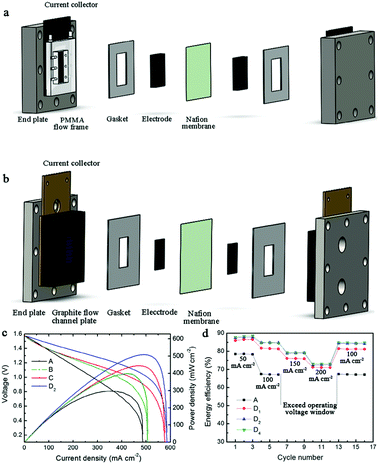 | ||
| Fig. 4 Schematic of VFB components: (a) flow-through structure without flow fields; (b) flow-by structure with a single serpentine flow field. (c) Polarization curves of VFBs employing different electrodes (A: original graphite felt in flow-through structure, B: 1.5 mm graphite felt in flow-through structure, C: 1.5 mm graphite felt in flow-by structure, D2: 1.5 mm graphite felt coated with 2 mg cm−2 carbon nanoparticles in flow-by structure); (d) rate performance at different current densities.39 Reprinted with permission from ref. 39. Copyright Elsevier, 2016. | ||
The flow field between the current collector and the porous electrode can help distribute the electrolyte more uniformly with reasonable pumping power, thus effectually decreasing the concentration polarization.44,47 As a result, designing the flow field on electrodes is a very efficient and promising method that is expected to attract increasing attention. Zhao et al. analyzed and compared the performance of VFBs with and without flow fields (Fig. 5a).44 Moreover, they also investigated the effects of the flow rate on the battery polarization. Increasing the flow rate of the electrolytes led to an obvious decrease in the concentration polarization, particularly with flow fields (Fig. 2 and 5b–d). This phenomenon mainly arose from the more even ion distribution in both the in-plane and through-plane directions. Although the corresponding pumping power for the battery with a higher flow rate was consequently higher, an optimized value was obtained. Operating at the optimum flow rate, the VFB with flow fields showed lower charge voltage and higher discharge voltage, indicating the effects of flow fields on decreasing the battery polarization (Fig. 5e).
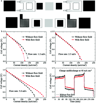 | ||
| Fig. 5 (a) Schematics of the components of VFBs with flow-through electrodes (up) without flow fields and (down) with serpentine flow fields, including polarization curves of the VFBs with and without flow fields at the flow rate of (b) 1.2 ml s−1; (c) 2.5 ml s−1; and (d) 5.0 ml s−1. (e) Charge–discharge performance of VFBs with and without flow fields.44 Reprinted with permission from ref. 44. Copyright Elsevier, 2014. | ||
In fact, the aforementioned approaches can address various polarization behaviors of VFBs. Different types of battery polarization are not affected by a single factor; the effects of these solutions are thus correlated and synergetic.28,43 The design of flow fields on electrodes and the optimization of the flowing behavior of electrolytes can decrease the concentration polarization. The introduction of carbon materials can also simultaneously address the issues of electrochemical polarization and concentration polarization. To illustrate this, Manthiram et al. utilized nitrogen-doped carbon nanotubes (N-CNTs) decorated on graphite felts to act as an electrode material for VFBs (Fig. 6).28 The uniform and dense distribution of N-CNT networks on the surface of the graphite felt contributed to the formation of a sufficiently porous electrode structure. The existence of this structure propelled the mass transport of the electrolytes. Also, the increased hydrophilicity resulting from the addition of N-CNT may also help decrease the concentration polarization. Additionally, the increased electrochemical surface area induced by the ideal porous graphite substrate and doped nitrogen atoms in the carbon lattice networks improved the electrocatalytic activity of the electrodes. Decreased electrochemical polarization was thus realized. Therefore, the capacity and the energy efficiency were both increased by utilizing the N-CNTs-decorated electrode materials (Fig. 6a and b).
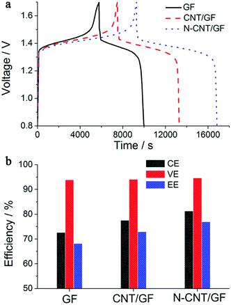 | ||
| Fig. 6 (a) Charge–discharge curves of VFBs with pristine GF (black), CNT/GF (red), and N-CNT/GF (blue) electrodes and (b) columbic efficiency, voltage efficiency, and overall energy efficiency values for the three electrode materials.28 Reprinted with permission from ref. 28. Copyright American Chemical Society, 2012. | ||
In short, the most commonly used electrode materials in VFB applications at present are felt materials, namely carbon and graphite felts. To ensure the minimum polarization in order to achieve higher power density, diverse modification methods have already been carried out on carbon and graphite felt electrodes. Among these methods, the introduction of materials that can produce oxygen-containing and nitrogen-containing groups as active sites is fairly effective. Also, this is one of the most promising methods to improve the electrocatalytic activity of electrodes. The electrochemical polarization then decreases. Proper compression of electrodes can decrease the thickness of the electrodes, thus increasing their conductivity. The ohmic polarization decreases as well. Moreover, the design of flow fields on the surface and in the interior of electrodes should receive increasing attention to decrease the concentration polarization, thus decreasing the cost of the VFB system. It is worth noting that a particular solution can often address one or more polarization problems. Therefore, further altering these modification methods of electrodes or seeking other available methods to combine the advantages and avoid the drawbacks of these methods can finally lead to optimal VFB performance, contributing to higher power density and lower cost of VFB systems. Moreover, selecting proper electrode materials with excellent pore structures to avoid the intrinsic deficiencies of felt electrodes may be another effective idea.
2.2 Electrolyte
Apart from the flow rate of the electrolytes, as illustrated above, the effects of other parameters relevant to electrolytes on the power density of VFBs are actually slight. However, the low solubility of vanadium ions in the supporting electrolyte and the precipitation of toxic V2O5 at elevated temperature impose severe restrictions on the energy density of VFBs.11,16,18,48–50 This is because the volume and concentration of the electrolytes determine the energy capacity of VFBs.11 As described above, VFB electrolytes employ vanadium ions with different valences as active species, while an aqueous sulfuric acid solution commonly serves as the supporting electrolyte. Commonly, the solubilities of V(II), V(III), and V(IV) ions in sulfuric acid supporting electrolytes increase with increasing temperature or decreasing concentration of the sulfuric acid solution, while the solubility of V(V) ions exhibits the opposite tendency. Thus, the low solubility of vanadium ions mainly arises because V(II), V(III), and V(IV) ions precipitate at low temperature, while V2O5 ions precipitate at high temperature.15,48,51 The poor solubility of vanadium ions in sulfate-based supporting electrolytes restricts the energy density of the current VFB systems to 30 to 40 W h L−1, while their weak thermal stability commonly leads to a narrow operating temperature range of 10 °C to 40 °C.17,51,52 To improve the energy capacity and further reduce the cost of VFB systems, as well as to widen the temperature range of VFB operation, variable optimizations on electrolytes have also been carried out. When sulfate-based solutions serve as supporting electrolytes, the solubility of vanadium ions strongly depends on the concentration of the sulfuric acid solution. As mentioned above, there may be a tradeoff in the concentration of sulfate-based solutions for higher solubility of vanadium ions.15,51 However, the effect of optimizing the concentration of the sulfuric acid solution to improve the solubility and thermal stability of vanadium ions is poor. Currently, more effective modification methods are the addition of proper additives as precipitation agents for vanadium ions in sulfate-based solutions and the use of mixed acid solutions as supporting electrolytes.51–57Another strategy is to introduce inorganic additives, such as phosphate-based additives, chloride-based additives, amine-based additives, and metal ions.51,56,57,65,66 The presence of metal ions, such as Cr3+ and In3+, also accelerates the electrocatalytic activity of electrolytes. The electrochemical reversibility and kinetics of redox couples are thus improved, which is analogous to the influence of introducing electrocatalysts on electrodes.51,57,65,67 However, adding metal ions to positive electrolytes to improve the concentration and thermal stability of VFB electrolytes is relatively rare. On the other hand, NH4+, PO43−, HPO42− and H2PO4− can coordinate or ion-pair with V(V) ions or can adsorb on their nucleation sites to prevent the crystallization of V2O5, thus improving the electrochemical activity of electrolytes.55,56,68 Their utilization is comparably more effectual and common. Roznyatovskaya et al. previously employed phosphoric acid as an additive to improve the thermal stability of the catholyte by inhibiting the precipitation of V(V) ions (Fig. 7a).66 The role played by phosphoric acid in stabilizing the catholyte at elevated temperature was ascribed to the interaction between phosphoric acid and V(V) monomers or dimers, which formed two different V(V)-phosphoric acid coordination compounds (Fig. 7a). The precipitation of V2O5 was thereby prolonged. Furthermore, M. Skyllas-Kazacos et al. utilized inorganic phosphate-based additives in a sulfate-based electrolyte (KS11), containing 1 wt% of K3PO4+ and 1 wt% of SHMP ((NaPO3)6) (KS: K is K3PO4, and S is SHMP) to improve the concentration of vanadium ions.69 The blocked precipitation was attributed to the release of phosphate ions (PO43−) from K3PO4 and PO3− ions from SHMP; these are believed to be adsorbed onto the nucleating ions or onto the growing crystals, inhibiting the further formation of vanadium crystals as illustrated above. Also, the presence of phosphate-based additives would not affect the reaction kinetics of the V(IV)/V(V) redox couples. The electrolyte containing 4 M V(V) solution in 6 M sulfate-based supporting electrolyte remained stable at 40 °C for 1000 h (Fig. 7b and c). Finally, a solution composed of 3.5 M V(V) in 5.7 M sulfate-based solution with an additive (KS11) was obtained and was found to be fairly promising for VFBs with high energy density at high temperature.
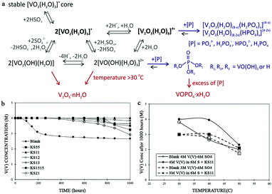 | ||
| Fig. 7 (a) Proposed pathways for V(V) precipitate formation in sulfuric acid electrolyte;66 (b) effects of different blends of KS formulation on the precipitation of V(V) solution at 40 °C; (c) effects of temperature on the performance of formulation KS11 using 3 M V(V) and 4 M V(V) solutions in 6 M sulphate/bisulphate after 1000 h.69 Reprinted with permission from ref. 66. Copyright Elsevier, 2017. Reprinted with permission from ref. 69. Copyright Elsevier, 2017. | ||
The introduction of additives into negative electrolytes can improve the stability of the electrolytes at low temperature by preventing V(II) and V(III) ions from precipitating; these additives include polyacrylic acid (PA), glycerol, ammonium phosphate, ammonium sulfate, Flucon-100, sodium pentapolyphosphate, and metal ions.48,53,70 Their acting mechanisms are analogous to those of the additives in positive electrolytes. However, the energy density of VFB systems is mainly confined by the precipitation of V2O5 at elevated temperature. Increasing numbers of inorganic phosphate-based precipitation inhibitors will be developed to be added to sulfate-based supporting electrolytes in the near future, due to their aforementioned merits.
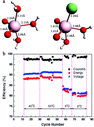 | ||
| Fig. 8 (a) Structures of V5+ complexes in sulfate and sulfate–chloride mixed solutions, as predicted by quantum calculation. The pink, green, red, and white spheres represent vanadium, chloride, oxygen, and proton ions, respectively. (b) Performance of a VFB with a 2.5 M vanadium mixed solution at 40 °C, 50 °C, 5 °C, and 0 °C.54 Reprinted with permission from ref. 54. Copyright John Wiley and Sons, 2011. | ||
The ideas and acting mechanisms of adding precipitation inhibitors and utilizing mixed acid supporting electrolytes are analogous. In addition to these two methods, controlling the state of charge (SOC) of the battery is sometimes employed. This is because changes in the density and viscosity of the electrolytes, which are closely related to their conductivity, can be regarded as a function of the SOC (or the oxidation state of vanadium ions). Therefore, variations in the SOC will influence the solubility and stability of VFB electrolytes to a certain degree.18,72 However, to avoid precipitation of V2O5, the SOC must be decreased, which will cause a decrease in the energy density.51 As a consequence, it is comparably difficult to prevent capacity loss by controlling the SOC. However, the SOC is also closely related to the imbalance of positive and negative half-cell electrolytes, which can lead to a decrease in the efficiency and capacity of VFBs.73,74 Real-time measurement and analysis of the SOC on each side of the VFB electrolyte enables in situ study of the electrolyte, which is useful for estimating capacity loss and achieving high system effectiveness.73,74
2.3 Membranes
The polarization induced by VFB membranes is mainly ohmic polarization. Especially at higher current densities, serious ohmic polarization caused by hindered and difficult mass transport results in high voltage loss. Also, the ionic and contact resistance between the membrane and electrode normally result in ohmic polarization.47 At present, commercial perfuorinated sulfonated membranes are still the most widely used membranes in VFBs in light of the ready degradation of other types of ion exchange membranes in the strong oxidized and acidic environment of VFBs.75–77 However, due to the low ion selectivity and high cost of perfuorinated sulfonated membranes, porous membranes with low cost are among the most promising alternatives for industrial VFB application.78 In the past few years, many modification methods have been carried out to optimize the performance of porous membranes in VFBs. Also, currently, the VFB performance of porous membranes is very high; thus, it is difficult to further improve their energy efficiency.78 The main challenge of porous membranes is their relatively low voltage efficiencies at higher current densities (Fig. 9). In fact, the columbic efficiency of VFBs using porous membranes normally remains unchanged with increasing current density (Fig. 9). Thus, the decreased voltage efficiency also leads to decreased energy efficiency at high current densities.79–83 This serious voltage loss at high current densities constricts improvement in the power density. Decreases in the cost of VFB systems will be prevented as well.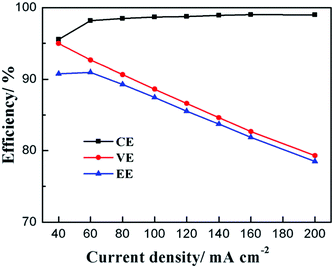 | ||
| Fig. 9 Variations in porous membrane performance in VFBs at different current densities.79 Reprinted with permission from ref. 79. Copyright Royal Society of Chemistry, 2016. | ||
The voltage efficiency of VFBs at high current densities is closely related to their ion conductivity, or in other words, the resistance of the membrane under VFB operating conditions. Lower resistance can accelerate mass transport at high current densities, resulting in lower ohmic polarization.84,85 In general, larger pore size, higher pore interconnectivity, wider pore size distribution, a thinner membrane and higher membrane hydrophilicity contribute to higher ion conductivity of porous membranes. However, there is a conflict between high conductivity and high selectivity, and these methods commonly lead to lower ion selectivity of membranes. When attempting to improve the voltage efficiency, high columbic efficiency at elevated current densities must be simultaneously ensured to minimize capacity loss. In fact, modifying porous membranes with the sole purpose of decreasing the battery voltage loss at high current densities is impractical. To date, most modifications of porous membranes have aimed to balance the conflict between high ion selectivity and high ion conductivity. A high voltage efficiency at high current density is generally achieved by improving the overall performance of porous membranes. Also, optimizing the overall performance of porous membranes achieves high ion selectivity, high ion conductivity and high chemical stability at the same time. The energy efficiency, the energy density and the power density can be accordingly enhanced as well.
To date, structure design and optimization of porous membranes has been the most effective method to improve their comprehensive performance.78 These methods include optimizing preparation parameters, introducing hydrophilic inorganic-based nanoparticles or charged groups, studying the formation mechanism of the porous membranes, and selecting novel high-performance membrane materials.78,86–90 For a complete modifying process, when the membrane materials have been selected, the preparation parameters should be first optimized to tune the membrane pore structures preliminarily. The initial performance of porous membranes determines whether a modification method should be carried out or which modification method should be employed. However, simple optimization of the preparation parameters during the fabrication process has finite effects on improving the membrane performance. Also, the utilization of hydrophilic inorganic-based nanoparticles often leads to higher membrane resistance.91,92 It is also difficult to maintain structure integration of nanoparticle-decorated porous membranes over long cycling times. Additionally, the introduction of charged groups can weaken the chemical stability of porous membranes because of their ready degradation.75–78,86,87 The studies on the formation mechanism of porous membranes are too complex to be put into practice. Moreover, identifying appropriate novel membrane materials will require much time. Actually, a large number of modification methods concentrate on offsetting the intrinsic drawbacks of membrane materials. For example, the purpose of introducing hydrophilic inorganic-based nanoparticles or charged groups is normally to overcome the high hydrophobicity of membranes. As a consequence, if the membrane material is very well chosen, it is relatively facile to achieve high performance for VFBs assembled with porous membranes. In this case, simple modification can enable preparation of a high-performance porous membrane for VFBs.
Yuan et al. used polybenzimidazole (PBI) as a porous membrane material for the first time (Fig. 10).90 The advantages of PBI lie in its outstanding thermal, mechanical and chemical stabilities as well as the high hydrophilicity conferred by its amine groups (Fig. 10a). Furthermore, the presence of ion exchange groups directly in the backbone of PBI will not sacrifice the chemical stability of the membranes. Therefore, there is almost no need to introduce any hydrophilic groups to improve the membrane hydrophilicity or carry out other approaches to enhance the membrane stability. They only optimized the casting thickness during the process of vapor-induced phase inversion to obtain sponge-like porous PBI membranes with highly excellent performance in VFBs (Fig. 10b). The VFB assembled with the optimal porous PBI membrane (PBI-68) demonstrated a columbic efficiency of nearly 100%, a voltage efficiency of 78.47%, and an energy efficiency of 78.05% at a high current density of 200 mA cm−2; these were all much higher than the corresponding values of commercial Nafion 115 (Fig. 10c). Also, the VFB could continually run for over 13![[thin space (1/6-em)]](https://www.rsc.org/images/entities/char_2009.gif) 000 cycles, with no obvious efficiency decline being observed (Fig. 10d). Due to this excellent performance, the optimized porous PBI membrane was utilized in a kW stack, and the stack performance indicated the high reliability and practicality of the prepared membrane.
000 cycles, with no obvious efficiency decline being observed (Fig. 10d). Due to this excellent performance, the optimized porous PBI membrane was utilized in a kW stack, and the stack performance indicated the high reliability and practicality of the prepared membrane.
 | ||
| Fig. 10 (a) Proton conducting mechanism of the prepared membranes. (b) Scanning electron microscope image showing the morphology of the membrane cross section; scale bar, 5 mm. (c) Cycling performance of a VFB using PBI-34 and PBI-68 membranes at different current densities. (d) Long-term stability test of a VFB assembled with a PBI-68 membrane at various current densities.90 Reprinted with permission from ref. 90. Copyright Royal Society of Chemistry, 2016. | ||
In summary, enhancing the overall performance of porous membranes in VFBs, namely by realizing a perfect balance between their selectivity and conductivity, is vital to maintain high columbic efficiency and decrease voltage loss at high current density. High energy density and power density can thus be effectively achieved. Although the aforementioned modification methods can address the deficiencies of porous membranes to a very large degree, the disadvantages of these methods also result in other problems. Therefore, the choice of excellent membrane materials with outstanding features, such as high stability, high hydrophilicity and low cost, is the most significant aspect to realize the successful industrial application of porous membranes in VFBs. The modifications of the membranes should be as simple as possible.
2.4 Models and simulations of VFB systems
In general, the mechanisms and processes of VFB systems, such as the ion transport mechanism and the capacity decay mechanism, are very complex and obscure. Traditional laboratory studies of these mechanisms and processes require great expense of time and cost. Moreover, direct laboratory testing of the key materials of VFBs is relatively complicated, time-consuming, and not highly effective.93 The relevant mechanisms attained by investigations on models and simulations of VFBs provide theoretical foundations to guide the design of VFBs and optimization of their performance. To date, there has been considerable investigation of models and simulations of VFBs to study the various mechanisms and process existing in VFB systems, such as their thermal behavior, the Donnan effect at the membrane/electrolyte (M/E) interfaces, the effects of ion concentration on the ion mobility, hydrogen evolution effects, the ion transport mechanism across the membrane, the self-discharge process, and dynamic performance in VFBs.94–100 Therefore, these models and simulations can predict the performance of VFB systems to a certain degree. The effects exerted by variations in the relevant parameters on the performance of VFBs, such as the dynamic diffusion coefficient of vanadium ions, the pressure drop, the electrode thickness and the flow rate of electrolytes, can be illustrated as well. Zhao et al. have developed a two-dimensional, transient model to investigate the mechanisms of ion transport across a commercially available porous separator in VFBs; they also studied the effects of these mechanisms on battery performance (Fig. 11).98 Their purpose was to study the relationship between the key properties of porous separators and the performance of VFBs. After validating the effectiveness and fidelity of the model, they investigated the effects of the pore diameter, the separator thickness, and the operation conditions (Fig. 11a–c). The results showed that the transport mechanism of vanadium ions across available separators was dominated by convection. Decreasing the pore size to less than 15 nm could effectively minimize the convection-driven vanadium-ion crossover. However, further reduction in migration- and diffusion-driven vanadium-ion crossover could only be realized when the pore size was reduced to a level close to the size of the vanadium ions. The operating conditions, such as the pressure on each half-cell of a VFB, played an important role in the vanadium-ion crossover rate across the available separators. Based on these conclusions, porous membranes with better performance can be designed and fabricated by balancing the proton transport and transfer of vanadium ions and by adjusting the operating conditions of VFBs.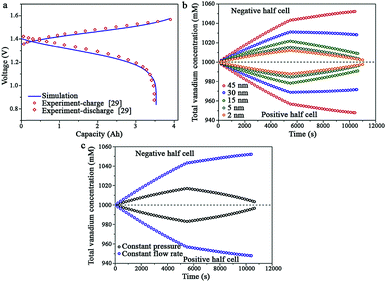 | ||
| Fig. 11 (a) Comparison of the simulated charge–discharge curve with experimental data; (b) predicted changes in the total amount of vanadium ions during the charge–discharge process at positive and negative half-cells for porous separators with different pore sizes; (c) predicted changes in the total amounts of vanadium ions during the charge–discharge process at positive and negative half-cells with a 30 nm porous separator with different operation modes and a 5 nm porous separator with different operation modes.98 Reprinted with permission from ref. 98. Copyright Elsevier, 2016. | ||
Investigations on models and simulations of VFB systems are useful in designing better flow fields on electrodes and optimizing the flowing behavior of electrolytes.101,102 Additionally, these investigations can guide the creation of entirely novel VFB battery structure designs, like the circular vanadium flow battery, to address the issue of the low energy density of VFBs systems.103 The discrepancies in the results derived from dynamic models and experimental values are normally less than those using pure mathematical models or stationary models.99 In future, more effective and more accurate models and simulations should be built to study the various mechanisms and operating process of VFBs more deeply and precisely. However, at all events, although variable models and simulations can improve the convenience of experiments, the results of these studies still need to be verified by laboratory tests in order to truly utilize them in practical applications.
3. Summary and perspective
High cost is the main limitation for the successful industrialization of VFBs in the field of large-scale energy storage. Improvements in the current density of VFB systems lead to severe polarization, contributing to lower power density. The power density and energy density strongly depend on the performance of key VFB materials, including the chemistry of the electrodes, the concentration and stability of the electrolytes, and the ion selectivity and ion conductivity of the membranes. Of course, the cost of these key materials must be as low as possible.The chemistry of the electrodes largely affects the polarization of VFB systems, including electrochemical polarization, ohmic polarization and concentration polarization. At present, carbon felts and graphite felts are the most commonly used electrode materials. To effectually improve the power density of a VFB system, necessary modifications have been carried out on felt materials. Carrying out surface treatments on electrodes can produce more active sites for redox reactions of VFB active species. The electrocatalytic reactivity of the electrodes is thereby improved. Compression of porous electrodes to decrease the thickness of the electrodes can improve their conductivity, thus decreasing the ohmic polarization. Furthermore, the electrode materials must possess high mechanical and chemical stability to maintain stable performance under the strongly oxidizing and acidic VFB operation conditions.
Due to the low solubility and poor thermal stability of vanadium ions in supporting electrolytes, VFB systems operate with low electrolyte concentrations and in narrow temperature ranges. These are the main reasons for the low energy density of VFB systems. In other words, these issues restrict the realization of low-cost VFB systems. The addition of inorganic precipitation inhibitors is an effective method to improve the concentration of vanadium ions in supporting electrolytes and prevent vanadium ions from precipitating. The utilization of mixed acid solutions and control of the SOC can also modify the concentration and stability of electrolytes to a degree.
The performance of membranes affects not only the power density but also the energy density of VFB systems. High ion selectivity and high ion conductivity at high current densities ensure simultaneous increase of the power density and energy density. Also, high columbic efficiency and high voltage efficiency at high current densities result in high energy efficiency of VFB systems. Porous membranes are among the most promising alternatives to the current commercial perfluorinated sulfonated membranes with both low ion selectivity and high cost. Of course, some modification methods are still required to enhance the performance of porous membranes in VFBs. However, proper choice of membrane materials is the most pivotal aspect and can eliminate unnecessary modification processes to a large degree. Materials with high selectivity and conductivity, high mechanical and chemical stability, high hydrophilicity and low cost are preferred membrane materials.
In addition, to save time and cost, investigations on models and simulations of VFB systems on various mechanisms and processes may be necessary. The effects exerted by variations in relevant parameters on the battery performance can be relatively well clarified. Although there is a certain deviation between the results arising from models and simulations and those originating from experiments, the results originating from these models and simulations can theoretically effectively direct the optimization of VFB performance.
In summary, the developing trends of VFB systems are low cost and minimum polarization at high current densities. Modifications of key VFB materials, along with investigations on models and simulations of VFB systems, will effectively optimize their overall performance. VFB systems will thus achieve successful industrialization in large-scale energy storage applications in the future.
Conflicts of interest
There are no conflicts to declare.Acknowledgements
Financial support of our work by the China Natural Science Foundation (Grant No. 21476224), the Outstanding Young Scientist Foundation, Chinese Academy of Sciences (CAS), Science and Technology Service Network Initiative (KFJ-EW-STS-108) and National Youth Top-notch Talent Program and Key project of Frontier Science, CAS (QYZDB-SSW-JSC032) is greatly acknowledged.References
- Z. Yang, J. Zhang, M. C. W. Kintner-Meyer, X. Lu, D. Choi, J. P. Lemmon and J. Liu, Chem. Rev., 2011, 111, 3577 CrossRef CAS PubMed.
- F. Díaz-González, A. Sumper, O. Gomis-Bellmunt and R. Villafáfila-Robles, Renewable Sustainable Energy Rev., 2012, 16, 2154 CrossRef.
- W. Wang, Q. Luo, B. Li, X. Wei, L. Li and Z. Yang, Adv. Funct. Mater., 2013, 23, 970 CrossRef CAS.
- M. Skyllas-Kazacos, M. H. Chakrabarti, S. A. Hajimolana, F. S. Mjalli and M. Saleem, J. Electrochem. Soc., 2011, 158, R55 CrossRef CAS.
- P. Leung, X. Li, C. Ponce de Leon, L. Berlouis, C. T. J. Low and F. C. Walsh, RSC Adv., 2012, 2, 10125 RSC.
- G. L. Soloveichik, Nature, 2014, 505, 163 CrossRef CAS PubMed.
- M. Skyllas-Kazacos, G. Kazacos, G. Poon and H. Verseema, Int. J. Energy Res., 2010, 34, 182 CrossRef CAS.
- A. Weber, M. Mench, J. Meyers, P. Ross, J. Gostick and Q. Liu, J. Appl. Electrochem., 2011, 41, 1137 CrossRef CAS.
- C. Ponce de León, A. Frías-Ferrer, J. González-García, D. A. Szánto and F. C. Walsh, J. Power Sources, 2006, 160, 716 CrossRef.
- G. Kear, A. A. Shah and F. C. Walsh, Int. J. Energy Res., 2012, 36, 1105 CrossRef CAS.
- C. Ding, H. Zhang, X. Li, T. Liu and F. Xing, J. Phys. Chem. Lett., 2013, 4, 1281 CrossRef CAS PubMed.
- Z. Yang, J. Zhang, M. C. Kintnermeyer, X. Lu, D. Choi, J. P. Lemmon and J. Liu, Chem. Rev., 2011, 111, 3577 CrossRef CAS PubMed.
- C. P. D. León, A. Frías-Ferrer, J. González-García, D. A. Szánto and F. C. Walsh, J. Power Sources, 2006, 160, 716 CrossRef.
- L. Xianfeng, Z. Huamin, M. Zhensheng, Z. Hongzhang and V. Ivo, Energy Environ. Sci., 2011, 4, 1147 Search PubMed.
- F. Rahman and M. Skyllas-Kazacos, J. Power Sources, 2009, 189, 1212 CrossRef CAS.
- A. Parasuraman, T. M. Lim, C. Menictas and M. Skyllas-Kazacos, Electrochim. Acta, 2013, 101, 27 CrossRef CAS.
- C. Álvaro, F. P. Brito, J. Martins, N. Rodrigues, V. Monteiro, J. L. Afonso and P. Ferreira, Energy, 2016, 115, 1478 CrossRef.
- M. Skyllas-Kazacos, L. Cao, M. Kazacos, N. Kausar and A. Mousa, ChemSusChem, 2016, 9, 1521 CrossRef CAS PubMed.
- K. Ki Jae, P. Min-Sik, K. Young-Jun, K. Jung Ho, D. Shi Xue and M. Skyllas-Kazacos, J. Mater. Chem., 2015, 3, 16913 RSC.
- Z. H. Zhang, T. S. Zhao, B. F. Bai, L. Zeng and L. Wei, Electrochim. Acta, 2017, 248, 197 CrossRef CAS.
- B. Li, M. Gu, Z. Nie, Y. Shao, Q. Luo, X. Wei, X. Li, J. Xiao, C. Wang and V. Sprenkle, Nano Lett., 2013, 13, 1330 CrossRef CAS PubMed.
- L. Wei, T. S. Zhao, L. Zeng, Y. K. Zeng and H. R. Jiang, J. Power Sources, 2017, 341, 318 CrossRef CAS.
- Q. Xu and T. S. Zhao, Phys. Chem. Chem. Phys., 2013, 15, 10841 RSC.
- D. Aaron, Z. Tang, A. B. Papandrew and T. A. Zawodzinski, J. Appl. Electrochem., 2011, 41, 1175 CrossRef CAS.
- C. Ding, H. Zhang, X. Li, T. Liu and F. Xing, J. Phys. Lett., 2013, 4, 1281 CAS.
- K. J. Kim, M. S. Park, Y. J. Kim, J. H. Kim, S. X. Dou and M. Skyllas-Kazacos, J. Mater. Chem. A, 2015, 3, 16913 CAS.
- A. Parasuraman, T. M. Lim, C. Menictas and M. Skyllas-Kazacos, Electrochim. Acta, 2013, 101, 27 CrossRef CAS.
- S. Wang, X. Zhao, T. Cochell and A. Manthiram, J. Phys. Chem. Lett., 2012, 3, 2164 CrossRef CAS PubMed.
- L. Yue, W. Li, F. Sun, L. Zhao and L. Xing, Carbon, 2010, 48, 3079 CrossRef CAS.
- D. M. Kabtamu, J. Y. Chen, Y. C. Chang and C. H. Wang, J. Power Sources, 2017, 341, 270 CrossRef CAS.
- L. Wei, T. Zhao, L. Zeng, X. Zhou and Y. Zeng, Energy Technol., 2016, 4, 990 CrossRef CAS.
- L. Wei, T. S. Zhao, L. Zeng, X. L. Zhou and Y. K. Zeng, Appl. Energy, 2016, 180, 386 CrossRef CAS.
- Z. González, A. Sánchez, C. Blanco, M. Granda, R. Menéndez and R. Santamaría, Electrochem. Commun., 2011, 13, 1379 CrossRef.
- M. H. Moghim, R. Eqra, M. Babaiee, M. Zarei-Jelyani and M. M. Loghavi, J. Electroanal. Chem., 2017, 789, 67 CrossRef CAS.
- C. Yao, H. Zhang, T. Liu, X. Li and Z. Liu, J. Power Sources, 2012, 218, 455 CrossRef CAS.
- Z. González, C. Flox, C. Blanco, M. Granda, J. R. Morante, R. Menéndez and R. Santamaría, J. Power Sources, 2017, 338, 155 CrossRef.
- K. Bromberger, J. Kaunert and T. Smolinka, Energy Technol., 2014, 2, 64 CrossRef CAS.
- T. C. Chang, J. P. Zhang and Y. K. Fuh, J. Power Sources, 2014, 245, 66 CrossRef CAS.
- L. Wei, T. S. Zhao, G. Zhao, L. An, L. Zeng and J. Yan, Appl. Energy, 2016, 176, 74 CrossRef CAS.
- A. Bhattarai, N. Wai, R. Schweiss, A. Whitehead, T. M. Lim and H. H. Hng, J. Power Sources, 2017, 341, 83 CrossRef CAS.
- G. Wei, J. Liu, H. Zhao and C. Yan, J. Power Sources, 2013, 241, 709 CrossRef CAS.
- Q. H. Liu, G. M. Grim, A. B. Papandrew, A. Turhan, T. A. Zawodzinski and M. M. Mench, J. Electrochem. Soc., 2012, 159, A1246 CrossRef CAS.
- X. L. Zhou, Y. K. Zeng, X. B. Zhu, L. Wei and T. S. Zhao, J. Power Sources, 2016, 325, 329 CrossRef CAS.
- Q. Xu, T. S. Zhao and C. Zhang, Electrochim. Acta, 2014, 142, 61 CrossRef CAS.
- Q. Xu, T. S. Zhao and P. K. Leung, Appl. Energy, 2013, 105, 47 CrossRef CAS.
- H. J. Lee, N. H. Choi and H. Kim, J. Electrochem. Soc., 2014, 161, A1291 CrossRef CAS.
- D. S. Aaron, Q. Liu, Z. Tang, G. M. Grim, A. B. Papandrew, A. Turhan, T. A. Zawodzinski and M. M. Mench, J. Power Sources, 2012, 206, 450 CrossRef CAS.
- J. Zhang, L. Li, Z. Nie, B. Chen, M. Vijayakumar, S. Kim, W. Wang, B. Schwenzer, J. Liu and Z. Yang, J. Appl. Electrochem., 2011, 41, 1215 CrossRef CAS.
- H. Zhangxing, L. Jianlei, H. Huiguo, C. Yong, Z. Zhi, Z. Shijie, L. Wei, L. Suqin and H. Zhen, Electrochim. Acta, 2013, 106, 556 CrossRef PubMed.
- S. Peng, N. Wang, C. Gao, Y. Lei, X. Liang, S. Liu and Y. Liu, Int. J. Electrochem. Sci., 2012, 7, 2440 CAS.
- C. Choi, S. Kim, R. Kim, Y. Choi, S. Kim, H. Y. Jung, J. H. Yang and H. T. Kim, Renewable Sustainable Energy Rev., 2017, 69, 263 CrossRef CAS.
- S. Kim, M. Vijayakumar, W. Wang, J. Zhang, B. Chen, Z. Nie, F. Chen, J. Hu, L. Li and Z. Yang, Phys. Chem. Chem. Phys., 2011, 13, 18186 RSC.
- A. Mousa and M. Skyllas-Kazacos, ChemElectroChem, 2016, 2, 1742 CrossRef.
- L. Li, S. Kim, W. Wang, M. Vijayakumar, Z. Nie, B. Chen, J. Zhang, G. Xia, J. Hu and G. Graff, Adv. Energy Mater., 2011, 1, 394 CrossRef CAS.
- M. Skyllas-Kazacos, J. Electrochem. Soc., 2016, 163, A5023 CrossRef.
- N. Kausar, A. Mousa and M. Skyllas-Kazacos, ChemElectroChem, 2016, 3, 276 CrossRef CAS.
- C. Ding, X. Ni, X. Li, X. Xi, X. Han, X. Bao and H. Zhang, Electrochim. Acta, 2015, 164, 307 CrossRef CAS.
- M. Skyllas-Kazacos, L. Cao, M. Kazacos, N. Kausar and A. Mousa, ChemSusChem, 2016, 9, 1521 CrossRef CAS PubMed.
- M. Kazacos and M. S. Kazacos, EP Pat., EP0729648, 1997 Search PubMed.
- L. Sha, K. Huang, S. Liu, F. Dong, X. Wu, L. Dan and W. Tao, Electrochim. Acta, 2011, 56, 5483 CrossRef.
- X. Wu, S. Liu, N. Wang, P. Sui and Z. He, Electrochim. Acta, 2012, 78, 475 CrossRef CAS.
- X. Liang, S. Peng, Y. Lei, C. Gao, N. Wang, S. Liu and D. Fang, Electrochim. Acta, 2013, 95, 80 CrossRef CAS.
- Z. He, J. Liu, H. Han, Y. Chen, Z. Zhou, S. Zheng, L. Wei, S. Liu and Z. He, Electrochim. Acta, 2013, 106, 556 CrossRef CAS.
- G. Wang, J. Chen, X. Wang, J. Tian, H. Kang, X. Zhu, Y. Zhang, X. Liu and R. Wang, J. Electroanal. Chem., 2013, 709, 31 CrossRef CAS.
- Z. He, L. Chen, Y. He, C. Chen, Y. Jiang, Z. He and S. Liu, Ionics, 2013, 19, 1915 CrossRef CAS.
- N. V. Roznyatovskaya, V. A. Roznyatovsky, C. C. Höhne, M. Fühl, T. Gerber, M. Küttinger, J. Noack, P. Fischer, K. Pinkwart and J. Tübke, J. Power Sources, 2017, 363, 234 CrossRef CAS.
- F. Huang, Q. Zhao, C. Luo, G. Wang, K. Yan and D. Luo, Chin. Sci. Bull., 2012, 57, 4237 CrossRef CAS.
- B. Hou and X. Cui, J. Residuals Sci. Technol., 2016, 13, 178.1 Search PubMed.
- F. Rahman and M. Skyllas-Kazacos, J. Power Sources, 2017, 340, 139 CrossRef CAS.
- J. Shen, S. Liu, Z. He and L. Shi, Electrochim. Acta, 2015, 151, 297 CrossRef CAS.
- S. Peng, N. F. Wang, X. J. Wu, S. Q. Liu, D. Fang, Y. N. Liu and K. L. Huang, Int. J. Electrochem. Sci., 2012, 7, 643 CAS.
- Q. Xu, T. S. Zhao and C. Zhang, Appl. Energy, 2014, 130, 139 CrossRef CAS.
- K. Ngamsai and A. Arpornwichanop, J. Power Sources, 2015, 298, 150 CrossRef CAS.
- K. Ngamsai and A. Arpornwichanop, J. Power Sources, 2015, 282, 534 CrossRef CAS.
- Z. Yuan, X. Li, Y. Zhao and H. Zhang, ACS Appl. Mater. Interfaces, 2015, 7, 19446 CAS.
- Z. Yuan, X. Li, Y. Duan, Y. Zhao and H. Zhang, J. Membr. Sci., 2015, 488, 194 CrossRef CAS.
- Z. Yuan, X. Li, J. Hu, W. Xu, J. Cao and H. Zhang, Phys. Chem. Chem. Phys., 2014, 16, 19841 RSC.
- W. Lu, Z. Yuan, Y. Zhao, H. Zhang, H. Zhang and X. Li, Chem. Soc. Rev., 2017, 46, 2199 RSC.
- W. Lu, Z. Yuan, Y. Zhao, X. Li, H. Zhang and I. F. J. Vankelecom, Energy Environ. Sci., 2016, 9, 2319 CAS.
- Z. Yuan, Q. Dai, Y. Zhao, W. Lu, X. Li and H. Zhang, J. Mater. Chem. A, 2016, 4, 12955 CAS.
- W. Lu, Z. Yuan, M. Li, X. Li, H. Zhang and I. Vankelecom, Adv. Funct. Mater., 2017, 27, 1604587 CrossRef.
- Y. Zhao, M. Li, Z. Yuan, X. Li, H. Zhang and I. F. J. Vankelecom, Adv. Funct. Mater., 2016, 26, 210 CrossRef CAS.
- W. Lu, Z. Yuan, Y. Zhao, L. Qiao, H. Zhang and X. Li, Energy Storage Materials, 2018, 10, 40 CrossRef.
- Y. Wang, S. Wang, M. Xiao, D. Han and Y. Meng, Int. J. Hydrogen Energy, 2014, 39, 16088 CrossRef CAS.
- X. Xi, C. Ding, H. Zhang, X. Li, Y. Cheng and H. Zhang, J. Power Sources, 2015, 274, 1126 CrossRef CAS.
- H. Zhang, H. Zhang, F. Zhang, X. Li, Y. Li and I. Vankelecom, Energy Environ. Sci., 2013, 6, 776 CAS.
- Y. Li, X. Li, J. Cao, W. Xu and H. Zhang, Chem. Commun., 2014, 50, 4596 RSC.
- Y. Li, H. Zhang, X. Li, H. Zhang and W. Wei, J. Power Sources, 2013, 233, 202 CrossRef CAS.
- Y. Li, H. Zhang, H. Zhang, J. Cao, W. Xu and X. Li, J. Membr. Sci., 2014, 454, 478 CrossRef CAS.
- Z. Yuan, Y. Duan, H. Zhang, X. Li, H. Zhang and I. Vankelecom, Energy Environ. Sci., 2016, 9, 441 CAS.
- H. Zhang, H. Zhang, X. Li, Z. Mai and W. Wei, Energy Environ. Sci., 2012, 5, 6299 CAS.
- Z. Yuan, X. Zhu, M. Li, W. Lu, X. Li and H. Zhang, Angew. Chem., Int. Ed. Engl., 2016, 55, 3058 CrossRef CAS PubMed.
- A. A. Shah, H. Al-Fetlawi and F. C. Walsh, Electrochim. Acta, 2010, 55, 1125 CrossRef CAS.
- Q. Zheng, H. Zhang, F. Xing, X. Ma, X. Li and G. Ning, Appl. Energy, 2014, 113, 1675 CrossRef CAS.
- Y. Lei, B. W. Zhang, B. F. Bai and T. S. Zhao, J. Power Sources, 2015, 299, 202 CrossRef CAS.
- X. L. Zhou, T. S. Zhao, L. An, Y. K. Zeng and X. H. Yan, Appl. Energy, 2015, 158, 157 CrossRef CAS.
- Z. Wei, J. Zhao, M. Skyllas-Kazacos and B. Xiong, J. Power Sources, 2014, 260, 89 CrossRef CAS.
- X. L. Zhou, T. S. Zhao, L. An, Y. K. Zeng and L. Wei, J. Power Sources, 2016, 327, 67 CrossRef CAS.
- D. You, H. Zhang, C. Sun and X. Ma, J. Power Sources, 2011, 196, 1578 CrossRef CAS.
- W. Xu, H. Zhang, X. Feng, H. Zhang, Y. Li, J. Cao and X. Li, Electrochim. Acta, 2014, 118, 51 CrossRef CAS.
- Q. Zheng, F. Xing, X. Li, G. Ning and H. Zhang, J. Power Sources, 2016, 324, 402 CrossRef CAS.
- S. König, M. R. Suriyah and T. Leibfried, J. Power Sources, 2016, 333, 134 CrossRef.
- Q. Zheng, X. Feng, X. Li, T. Liu, Q. Lai, G. Ning and H. Zhang, J. Power Sources, 2015, 277, 104 CrossRef CAS.
| This journal is © the Owner Societies 2018 |


