
 Open Access Article
 This Open Access Article is licensed under a Creative Commons Attribution-Non Commercial 3.0 Unported Licence
On the photocatalytic cycle of water splitting with small manganese oxides and the roles of water clusters as direct sources of oxygen molecules†
Kentaro
Yamamoto
 and
Kazuo
Takatsuka
*
and
Kazuo
Takatsuka
*
Fukui Institute for Fundamental Chemistry, Kyoto University, Sakyou-ku, Kyoto 606-8103, Japan. E-mail: kyamamoto@fukui.kyoto-u.ac.jp; kaztak@fukui.kyoto-u.ac.jp
First published on 19th February 2018
Abstract
We theoretically studied the chemical principles behind the photodynamics of water splitting: 2H2O + 4hν + M → 4H+ + 4e− + O2 + M. To comprehend this simple looking but very complicated reaction, the mechanisms of at least three crucial phenomena, among others, need to be clarified, each of which is supposed to constitute the foundation of chemistry: (i) charge separation (4H+ + 4e−), (ii) the catalytic cycle for essentially the same reactions to be repeated by each of four photon absorptions with a catalyst M, and (iii) the generation of oxygen molecules of spin triplet. We have previously clarified the photodynamical mechanism of charge separation, which we refer to as coupled proton electron-wavepacket transfer (CPEWT), based on the theory of nonadiabatic electron wavepacket dynamics [K. Yamamoto and K. Takatsuka, ChemPhysChem, 2017, 18, 537]. CPEWT gives an idea of how charge separation can be materialized at each single photon absorption. Yet, this mechanism alone cannot address the above crucial items such as (ii) the catalytic cycle and (iii) O2 formation. In the studies of these fundamental processes, we constructed a possible minimal chemical system and perform semi-quantitative quantum chemical analyses, with which to attain insights about the possible mechanisms of photochemical water splitting. The present study has been inspired by the idea underlying the so-called Kok cycle, although we do not aim to simulate photosystem II in biological systems in nature. For instance, we assume here that a catalyst M (actually simple manganese oxides in this particular study) is pumped up to its excited states leading to charge separation by four-time photon absorption, each excitation of which triggers individual series of chemical reactions including the reorganization of the hydrogen-bonding network (cluster) of water molecules surrounding the photocatalytic center. It is shown that in the successive processes of restructuring of the relevant water cluster, the O![[double bond, length as m-dash]](https://www.rsc.org/images/entities/char_e001.gif) O bond is formed and consequently an oxygen molecule of spin triplet can be isolated within a range of a given photon energy of about 3.0 eV.
O bond is formed and consequently an oxygen molecule of spin triplet can be isolated within a range of a given photon energy of about 3.0 eV.
1 Introduction
Photoinduced water oxidation, summarized as:| 2H2O + 4hν + M → 4H+ + 4e− + O2 + M, | (1) |
| 2H2O + 4hν + M → 2H2O + M* → 4H+ + 4e− + O2 + M, | (2) |
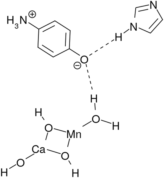
For this goal we tried to construct a basic model of the photocatalytic cycle that can realize the reaction of eqn (2) after the cycle of four photon absorption is completed. This system is composed of (a) Mn oxide (MnCaO4H5) as a photocatalytic center, (b) acceptors of protons and electrons after charge separation, (c) a hydrogen-bonding network (cluster) of water molecules surrounding and partially attached to the catalytic center, and (d) proton and electron buffering subsystems (molecules) to regulate the relevant oxidation–reduction reactions in the water cluster. We show in terms of this system that each photon absorption by the catalyst triggers individual series of chemical reactions including reorganization of the hydrogen-bonding network of water molecules and O–O bond formation, as a peroxide in it can eventually lead to generation of spin-triplet O2. Therefore oxygen molecules are extracted out of abundant bulk water, which is stably and continuously supplied from the surroundings.
Our former studies related to water splitting have been mainly aimed at identification of the chemical dynamics of charge separation. Indeed, we have proposed a quantum mechanical mechanism of charge separation catalyzed by Mn oxides through nonadiabatic dynamics calculations in simple systems.3–5 In these studies we have elucidated (i) the (quantum) dynamical mechanism(s) of charge separation to create protons and electrons, and (ii) the conditions that the proton–electron acceptor(s) should satisfy to enable the reaction to take place. For instance, the role of the Rydberg-like diffused vacant states on the nitrogen atoms involved in the amino acid residues which act as electron acceptors, has been clarified. More precisely, the proton involved in the relay-transfer is not bare but covered with as many as around 0.5 electrons as in ground-state proton transfer.6 The residual ∼0.5 electrons are transferred to the Rydberg-like states of the EA through different pathways of the proton relay-transfer. As a result, approximately ±0.5 charge separation is induced on the different acceptor molecules. We refer to the above mechanism as coupled proton electron-wavepacket transfer (CPEWT) to stress that we focus on dynamics that can be properly characterized by the theoretical framework of nonadiabatic electron-wavepacket dynamics. Also, particularly relevant to the present work is the charge transfer in the largest extended system with Y-shaped proton–electron acceptors,5 which is schematically expressed as:
 | (3) |
 | ||
| Fig. 1 A charge separation system studied in ref. 5 as a study of Y-shaped electron–proton acceptors. | ||
Incidentally the definition of “proton-coupled electron transfer” (PCET) by Hammes–Schiffer indicates a general phenomena including any type of mechanism in which proton and electron transfers somehow couple with each other.7,8 The dynamical mechanism illustrated in eqn (3) is also included within PCET by definition. However, PCET covers too broad a range to differentiate the precise phenomena and mechanisms. PCET has been widely studied,9–15 but among these studies, those of Domcke and coworkers16–32 are particularly relevant to the present work. They have extensively investigated static properties along the excited-state potential curves to consider mechanisms related to excited-state proton and/or electron transfer. Their studies have also covered artificial photochemical water-splitting.23–32 Water-splitting in this context is recognized as a photoinduced homolytic dissociation to obtain H˙ and OH˙. This photochemical reaction eventually produces H2 to store the photon energy in the form of chemical bonds, which can be regarded as artificial photosynthesis. Chromophores such as porphyrin and pyridine also serve as catalyzers. One of the significant similarities between Domcke's mechanism and ours is that conical intersections33 play important roles in splitting OH bonds.
Having mainly finished the study of the dynamical mechanism of photoinduced charge separation dynamics as above, we attempted to construct a chemical model of photocatalytic water splitting, inspired by the Kok cycle which is triggered by four-time photon absorption. After briefly describing the theoretical principles we used to construct the chemical model system in Sections 2.1 to 2.2, in Section 2.3 we propose a model reaction scheme that could materialize water splitting within a photon energy range of about 3 eV. In Section 3, we show the theoretical background from the viewpoint of nonadiabatic electron wavepacket dynamics for charge separation and feasibility of the concomitant chemical reactions from the viewpoint of energetics. We studied a possible mechanism for the formation of O2 molecules via water clusters contacting Mn-oxides. This paper concludes in Section 4 with some remarks.
2 Proposed reaction scheme of the water-splitting cycle
We first present our studied mechanism of the photocatalytic water splitting cycle using small Mn oxides, from which oxygen molecules can be generated via contact with water clusters. This is one of the possible mechanisms that we surveyed and verified in terms of quantum mechanical calculations, including electron wavepacket dynamics and energetics of key temporal species. The actual study proceeds in a manner of “propose and verify” or trial and error to find appropriate processes, and hence a naive way of presentation according to the chronological order proceeds back and forth. Therefore, for the sake of systematic presentation we first summarize the attained cyclic reaction mechanism in this section, and verify the individual pieces of the reaction in greater detail in the next section.2.1 Charge separation dynamics triggering characteristic sequences of reactions
 | (4) |
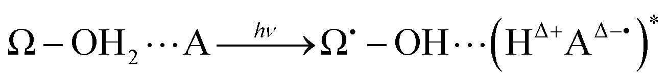
In this general model system, the proton and electron donor Ω–OH2 is assumed to directly attach to the acceptor A. However, it is usual experimental practice for these systems to be dipped in bulk water, the inner part of which is structured by hydrogen-bonding networks. Barry, Brahmachari and Guo34 emphasize the critical importance of tracking reactive water in hydrogen-bonding networks in their recent review article about photosynthetic oxygen evolution in PSII. Moreover, the chemical bond Ω–O is strong enough to be maintained as it is throughout the excited dynamics as in eqn (4). It is therefore hard for the OH2 in Ω–OH2 to be readily recycled for the system to repeat the reactions many times even if additional photons are provided. In other words, Ω–OH2 in this setting cannot serve as a catalyst by itself. A natural idea to make a first step towards more flexible and general systems is to examine whether the proton transfer in eqn (4) is still possible through a relay channel, schematically suggested to be:
 | (5) |
2.2 Photocatalytic cycle for water splitting and O2 generation
The present study surveys (i) how the hydrogen-bonding networks can revive the Ω˙–OH in its excited state (recall eqn (4)) back to Ω–OH2 in the ground state, thereby making it ready to absorb another photon to serve as a catalyst, and (ii) how oxygen molecules can be generated as a result of the series of reactions. We here propose a chemical model of the water-splitting cycle in which the system absorbs four photons to generate one molecule of oxygen. The mechanism is inspired by the Kok cycle (S-state cycle).35,36 We therefore refer to this bio-inspired simple mechanism as the “K-state cycle”, K0 → K1, K1 → K2, K2 → K3, and K3 → K0, the preview of which can be seen in Fig. 2. Along with the presentation of the details of the possible change of the states, we attempted to ensure that the involved reactions are energetically feasible.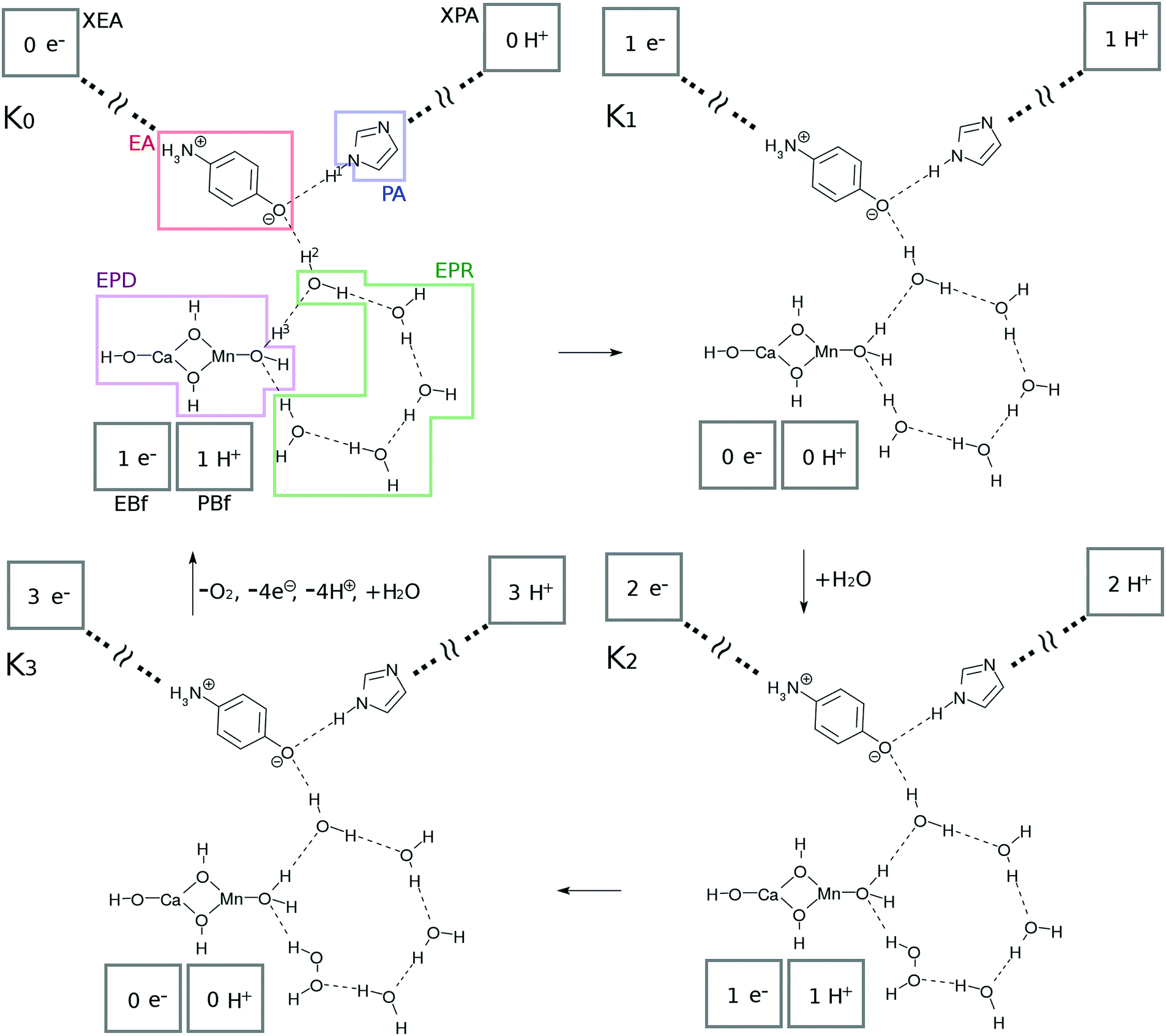 | ||
| Fig. 2 Schematic representation of the present photocatalytic water-splitting cycle. This cycle has four states referred to as “K-states” and each is triggered by CPEWT. See text for the labels and components involved. | ||
1. A single photon excitation of the Mn oxides initiates a single charge separation and a concomitant series of reactions in the water network. The four photon process makes a single circuit of the catalytic cycle. Each photoinduced charge separation dynamics takes place with the same CPEWT mechanism under a common optical source.
2. The electron and proton thus isolated by the photoinduced charge separation dynamics are supposed to be carried away to their own destinations, and will not come back to the K-state system.
3. The four individual subprocesses, K0 → K1, K1 → K2, K2 → K3, and K3 → K0, should share as many common elementary processes as possible. This mimics a kind of parsimony principle frequently found in biological systems, in which molecules and/or sets of molecular systems are utilized multiple times for different purposes so that the system is kept as compact and economical as possible.
4. The system should use materials and molecules that are available abundantly. Here, water is used.
Subsystems and their functions. We first show the basic units, K0, K1, K2, and K3 in Fig. 2, from which the four-photon catalytic reaction makes one complete cycle. Each of these is in its ground state and is waiting to absorb light. Upon excitation, the individual series of reactions follow the pathway shown in the next subsection.
The catalytic system commonly consists of subsystems, namely, an electron–proton donor (EPD = MnCa(OH)4), an electron acceptor (EA = O–C6H4–NH3), a proton acceptor (PA = C3N2H3), electron–proton resources (EPR = OH⋯(H2O)3⋯X, X = H2O for K0, K1 and H2O2 for K2, K3), and electron and proton buffering subsystems (EBf and PBf, respectively). Their chemical roles will be described in order.
This system is open (dissipative) to the surrounding environment; two water molecules are taken in from the outside while 4 protons, 4 electrons and one oxygen molecule are produced and transported out of the catalytic system.
Protons and electrons are transported to asymptotic sites. As Kn proceeds by one step (0 → 1 → 2 → 3 → 0), the electron and proton created in the photoinduced charge separation are eventually transported to XEA through EA, and XPA through PA, respectively (see Fig. 2). Thus the numbers of electrons and protons in XEA and XPA, respectively, increase one by one. XEA is defined to abstract the electron delivered to the Rydberg-like states of the EA as XEA–e− and is supposed to serve as an electron carrier like the quinones in PSII.1,2 The explicit mechanism of the electron abstraction is not addressed in the present paper, but its energy is considered later in the study of the energetics. Note that the XEA site has the capacity to accept electrons (modulo 4) after each photocatalytic cycle. XPA is similarly defined to abstract the proton of PA to become XPA–H+.
Hydrogen-bonding network. As seen in Fig. 2, there is a water molecule (H2OH in K0 of Fig. 2) in between EPD and EA linking them via hydrogen bonding. Notice that this particular water molecule was not considered in our former model of photoinduced charge separation dynamics, which is shown in Fig. 1. Thanks to this water, the charge separation center (EPD, EA, and PA units) is now attached to other water molecules, which constitutes a water cluster. Here we consider a six-membered cluster, since it is generally believed to stably exist in bulk water. However, our preliminary calculations show that the five-membered cluster works as well for O2 generation.
The system shown in Fig. 1 has been naturally extended so as to be electronically connected with the bulk water surrounding the charge separation site. Thus water molecules consumed in water splitting as in eqn (2) can be readily supplied and are now recyclable. The cost is the possibility of the breakdown of CPEWT through the mediating water molecule. Our critical computational finding is that photoinduced charge separation under the CPEWT mechanism is indeed possible in this system too, which will be explicitly shown in Section 3.
The system includes three hydrogen atoms which are involved in the proton relay-transfer of the CPEWT, the initial configuration of which is
| EPD–H3⋯EPR–H2⋯EA⋯H1–PA | (6) |
Electron- and proton-buffering in the catalytic cycle. Photoinduced charge separation and proton transfer through the configuration change as in eqn (6) should strongly affect the water cluster that is directly attached to the mediating water molecule. We here assume that different kinds of proton- and electron-transfers are induced in this water cluster, through which oxidation–reduction reactions and charge neutralization reactions take place in the water cluster too. Since the generated O2 is released (exhausted) asymptotically, another water molecule should be added into the cluster. For these reactions to proceed in low energy, we require the presence of buffering systems (molecules) that can store and release electrons and protons such as some amino acid residues (e.g. tyrosine and tryptophan37–41) or quinones in PSII.1,2 For instance, an electron buffer (EBf) captures electrons as EBf–e−, while EBf–e− releases an electron as EBf + e−. A similar relationship exists for proton buffer PBf and PBf–H+ in response to a change of environment.
The EBf is supposed to have two roles, namely, giving an electron to the EPD in the K0–K1 and K2–K3 transitions, and abstracting an electron from H2O (the K1–K2 transition) or H2O2 (the K3–K0 transition) of the EPR. The PBf has similar roles, exchanging protons from and to the cluster. In the present model setting, we do not specify the molecular species for EBf and PBf. However, the energetics with respect to PBf ↔ PBf–H+ and EBf ↔ EBf–e− will be discussed later in Section 3.4.
| 2H2O + 2hν → H2O2 + 2H+ + 2e− | (7) |
| H2O2 + 2hν → O2 + 2H+ + 2e− | (8) |
2.3 Reactions following each photoexcitation
After the charge separation dynamics occur upon photoexcitation of the Mn oxide in each K-state, characteristic reactions follow in the water cluster and the electron and proton buffers. Each elementary step of them is denoted as Knm (m = 1, 2, 3…), where the suffix n distinguishes the four K-states (K0 to K3) and m identifies the sequence of reactions after each photoexcitation. For instance, once K0 is excited, the reactions K01 to K16 follow (K01 to K03 are drawn in Fig. 3, while K04 to K1 are depicted in Fig. 4). The maximum number of m depends on n. For instance, K1 has a maximum of K16 whereas K04 is the last for K0.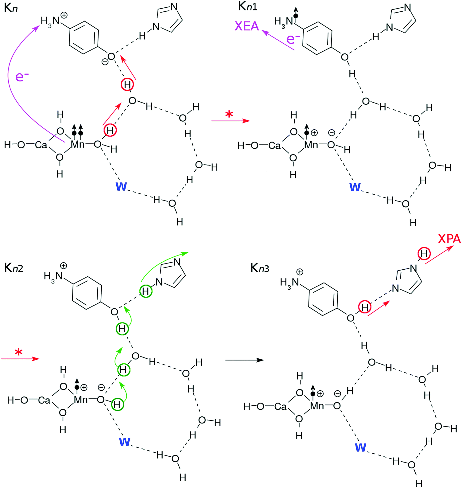 | ||
| Fig. 3 Reaction schemes commonly involved in the Kn–Kn+1 transition (n = 0, 1, 2 or 3 with K4 = K0), in which abstraction of an electron and a proton from “the core subsystem” take place. The atoms that are responsible for each reaction are indicated by circles and arrows (the straight ones schematically indicate transfer and the curly ones represent reorganization of the hydrogen bonds). The electron transfers are indicated by the arrows with “e−”. The “W” (blue bold letter) indicates a substitute, which is H2O for n = 0 or 1 and H2O2 for n = 2 or 3. The reactions in the electronic excited states are indicated by arrows with “*”. The dot-and-arrow symbols schematically indicate the locations of radicals. | ||
 | ||
| Fig. 4 Reaction schemes involved in the K0–K1 transition. The electron transfers are indicated by the arrows with “e−”. | ||
More precisely, the first process (Kn–Kn1) simply represents the elementary process of CPEWT, which is followed by electron transport to XEA (in Kn1) and proton relay transport (in Kn2–Kn3). The physical timing of these two transports is not specified here and should depend on a system under study.
The dynamics of CPEWT will be discussed in greater detail in Section 3. We do not address the electron abstraction mechanism from EA to XEA, but only the energetics are taken into account to confirm that the reaction is indeed possible. There are several mechanisms for the proton to be handed from the PA to the channel connected to the XPA. One possible way is a rotation of the PA. This motion will be accompanied by reorganization of the hydrogen-bond network. In the fourth step (Kn3–Kn4), the proton facing the external system is abstracted by the XPA. It involves proton transfer from the EA to the PA.
The processes resuming from Kn4 depend on n, as will be discussed next. This is because the configurations of the hydrogen-bonding network, PBf and EBf are different from one another, thereby distinguishing the evolutions of Kn (n = 0–3).
 | ||
| Fig. 5 Reaction schemes involved in the K1–K2 transition. The electron transfers are indicated by the arrows with “e−”. | ||
Two protons and two electrons are lost from the core subsystem of the K0 state, leaving HOOH behind. This implies that a vacancy in the water-cluster is made. To fill this vacancy in order to maintain the stability of the hydrogen-bonding network, a water molecule may be supplied from other surrounding places of bulk water to restore the network. This configuration is depicted in K2 in Fig. 5, which is in the ground state, awaiting the third photoexcitation.
 | ||
| Fig. 6 Reaction schemes involved in the K2–K3 transition. | ||
![[double bond, length as m-dash]](https://www.rsc.org/images/entities/b_char_e001.gif) O and making the cycle complete.
As shown in Fig. 7, the K3–K0 transition takes place through three steps triggered by photoexcited CPEWT due to the fourth photon (Fig. 3). The essential steps needed to complete the cycle, in which another water molecule is supplied from the bulk water and O2 is left behind, are schematically illustrated in Fig. 7. The series of elementary processes here are rather similar to those in the transitions of K14–K2 of Fig. 5.
O and making the cycle complete.
As shown in Fig. 7, the K3–K0 transition takes place through three steps triggered by photoexcited CPEWT due to the fourth photon (Fig. 3). The essential steps needed to complete the cycle, in which another water molecule is supplied from the bulk water and O2 is left behind, are schematically illustrated in Fig. 7. The series of elementary processes here are rather similar to those in the transitions of K14–K2 of Fig. 5.
 | ||
| Fig. 7 Reaction schemes involved in the K3–K0 transition. The electron transfers are indicated by the arrows with “e−”. These steps finally bring this system back to the K0 state. | ||
In the step K34–K35, the EBf and the PBf effectively abstract the electron and the proton from the H2O2 molecule, respectively, to generate a tentative hydroperoxyl radical OOH˙. In the step K35–K36, another proton and electron transfer from OOH˙ to the Mn-oxide site to neutralize the zwitter-ion pair (see K35). Once again these two elementary processes are likely to take place coherently. After all these transfers, an OO bond in spin triplet is released. The energetics of this reaction mechanism will be discussed in detail in Section 3.5.
Upon formation of the oxygen molecule, the hydrogen-bonding network can be disconnected and destabilized. Therefore, a supply of a water molecule is made possible as in K36, and the configuration of the core subsystem in K0 is restored, including those of the buffers EBf–e− and PBF–H+.
3 Charge separation dynamics and energetics behind the reaction mechanisms proposed: theoretical background
This section is devoted to showing the theoretical foundation of the proposed mechanism of the photocatalytic cycle of water splitting. Its background to verify the mechanism consists of two aspects: one is the photo-induced charge separation dynamics (coupled proton electron-wavepacket transfer (CPEWT)) studied by means of nonadiabatic electron wavepacket dynamics. The other is energetics with respect to the characteristic structure of molecular systems and their associated energies. We here assure that all of the reaction processes following the four individual photoexcitations can proceed within the tolerance of about 3 eV. Solvent effects due to the bulk water and possible protein moiety are not considered because of computational limitations.3.1 The theory of nonadiabatic electron wavepackets
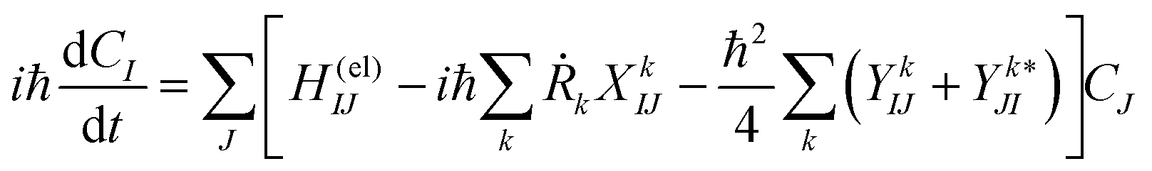
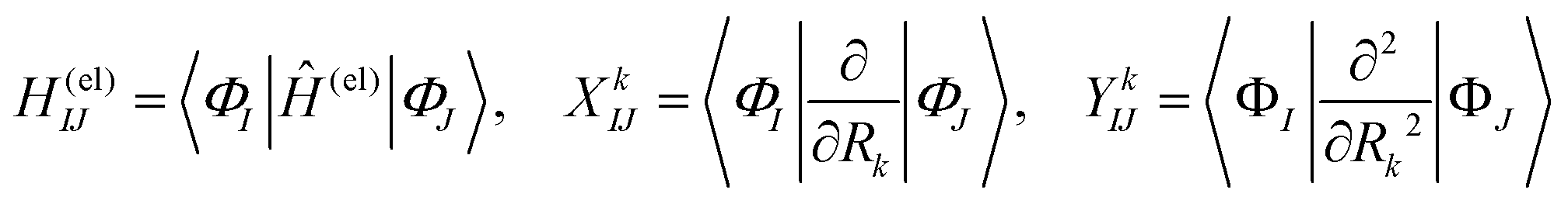
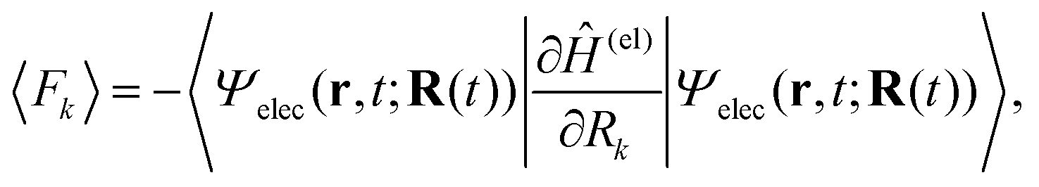
We briefly outline the theory of nonadiabatic electron-wavepacket dynamics, which plays an important role in characterizing the present mechanism. The full-dimensional nonadiabatic electron-wavepacket dynamics demonstrated herein are performed via the semiclassical Ehrenfest theory (SET).42–46 The SET is derived as an approximation to the path-branching representation theory.47–50 See ref. 4 for the path-branching dynamics on the relevant smaller systems. Here we only give a brief review of the path-branching representation and the derivation of the SET. See ref. 3–5 and 51–62 for applications. In this theory, electron dynamics is described in terms of the quantum wavepacket to be evolved in time along nuclear branching paths. The electron-wavepacket Ψelec(r,t;R(t)) is expanded in a series of time-independent wavefunctions {ΦI(r,R)} that are parameterized with nuclear geometry R at time t as in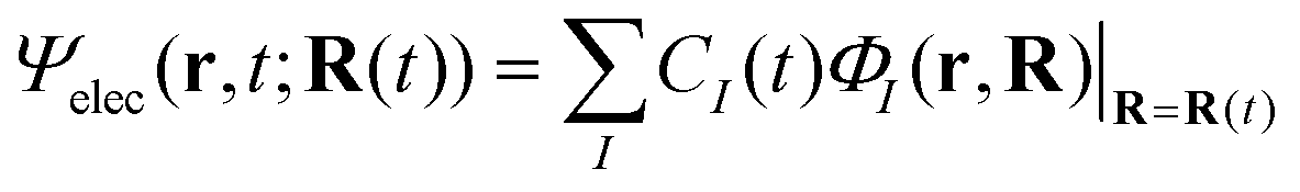 | (9) |
 | (10) |
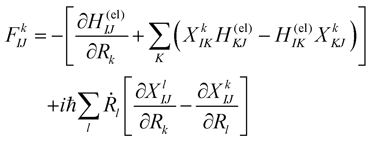
Here Ĥ(el) denotes the electronic Hamiltonian. Note that the scalar product in terms of the bra-ket notation in the present paper denotes the integration in terms of electronic coordinates. The terms multiplied by ħ2 in the right hand side of eqn (10) are the nontrivial correction to the conventional SET regarding electrons, but are usually neglected because of the presence of the small quantity ħ2.61 The nuclear path is driven by the force matrix FkIJ47–50 expressed as:
 | (11) |
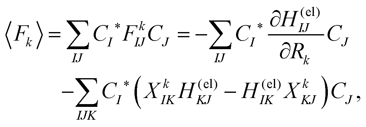 | (12) |
 | (13) |
3.2 Computational details
The atomic basis set chosen is basically common to all of the calculations performed in what follows, although different levels of computation are taken for different purposes. We employ the Stevens, Basch, Krauss, Jasien, and Cundari effective core potentials (SBKJC ECPs)63 for Mn and Pople's 6-31G for the other atoms. We add diffuse orbitals to the N and H (6-31++G) atoms of the EA. The diffuse orbitals are crucial in order to describe the present mechanism involving the dense manifold of the Rydberg-like states.3–5,64 All of the quantum chemical calculations are performed with use of the GAMESS quantum chemistry package,65,66 in which our original codes have been implemented to carry out the nonadiabatic electron wavepacket dynamics. For the geometry optimization to locate the stationary point geometry, we used the restricted (either closed-shell or open-shell) Hartree–Fock (RHF) method. Otherwise, the electronic wavepackets are represented in terms of linear combinations of many electronic configurations up to single and double excitations.3.3 CPEWT in triplet states involving a hydrogen-bond network
To track the dynamics we refer to the common core system of K0 and K1 as D11, whereas that of K2 and K3 as D21 (see Fig. 8). We first show numerically that the CPEWT previously found in simpler singlet systems3–5 also works in the present systems like D11 in a similar manner. Two major differences from what we did before are that the present systems have recyclable water molecules in the hydrogen-bond network, and they are spin triplet. In particular, it is far from obvious whether the CPEWT works in the presence of a hydrogen-bonding network, through which proton transfer can be driven along with electron transfer in different paths. Incidentally, a similar mechanism has been confirmed for the spin singlet counterpart as well.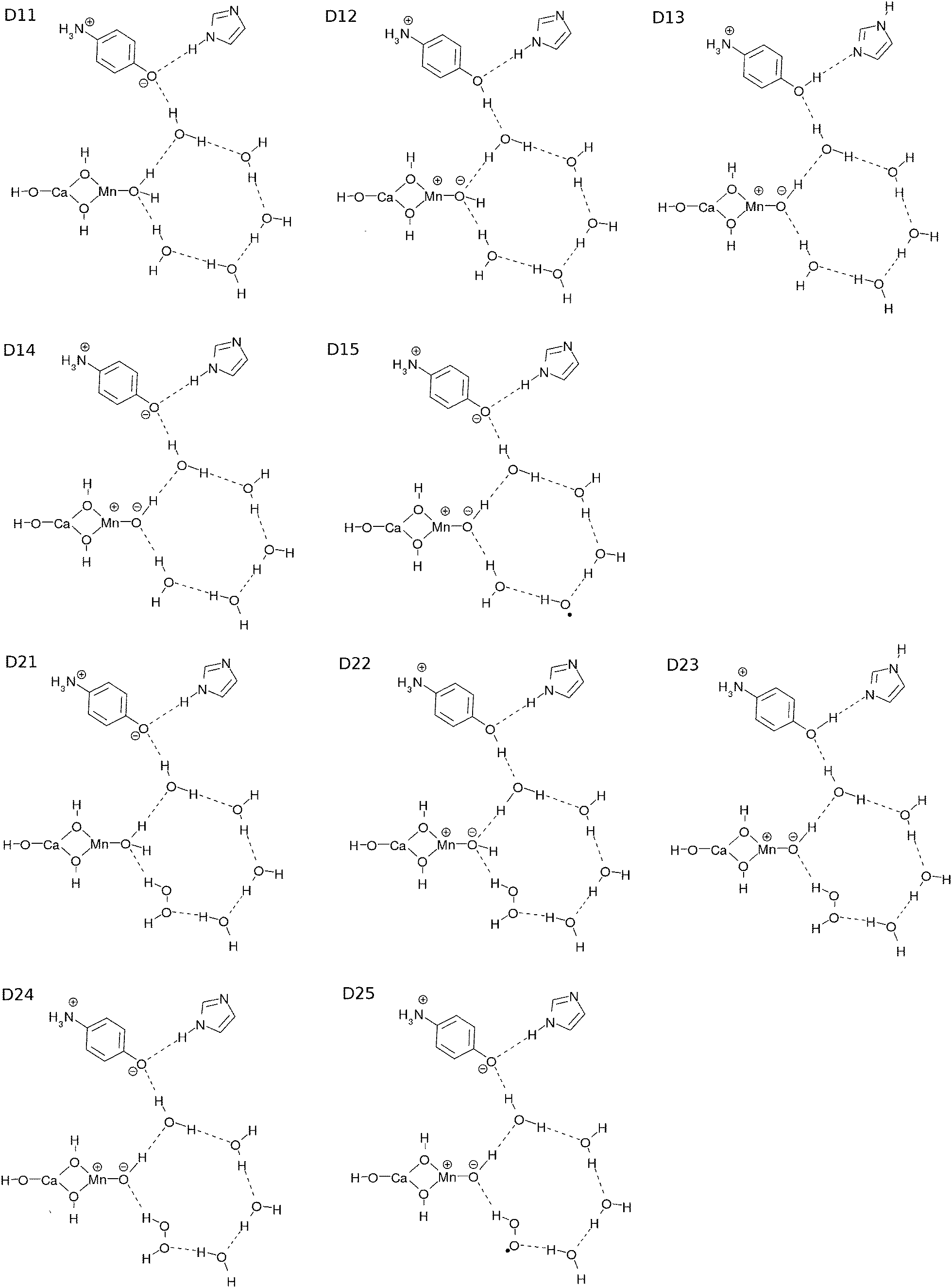 | ||
| Fig. 8 Projection of the local minima of the key structures. | ||
We employ the CISD/RHF (triplet) level of calculations and use the low-lying 150 adiabatic states for the wavefunction {ΦI} in eqn (10), in which CISD stands for configuration interaction of single and double excitations. The CISD active space is chosen as follows: the two SOMOs are employed to be the active MOs, while LUMO–(LUMO+89) are designated to be the active virtual MOs. All of the doubly occupied MOs and MOs higher than LUMO+89 are set to be inactive (frozen). The number of configuration state functions (CSFs) turns out to be 4186. We employ the triplet RHF for the geometry optimization only, since the ground state of this system in the CISD level calculations around the optimized geometry is known to be dominated by the RHF configuration.
Electron dynamics calculations with CISD/RHF in triplet state generally require multi-reference CI, in which multiple spin functions to describe the triplet are taken into account. If therefore we start from a single reference to propagate the wavepacket in CI, we often face discontinuity in the choice of the most appropriate spin function. This is because different single reference functions can give birth to (slightly) different sets of molecular orbitals. To circumvent this technical difficulty, multi-reference methods should be appropriately handled in such regions. However, this method costs much computational time and labor, and we connect the electron-wavepackets expanded in different reference sets of MOs at a path-point(s) of disconnection, so as to maximize the overlap of the electron-wavepackets. See Section S1 (ESI†) for the technical details.
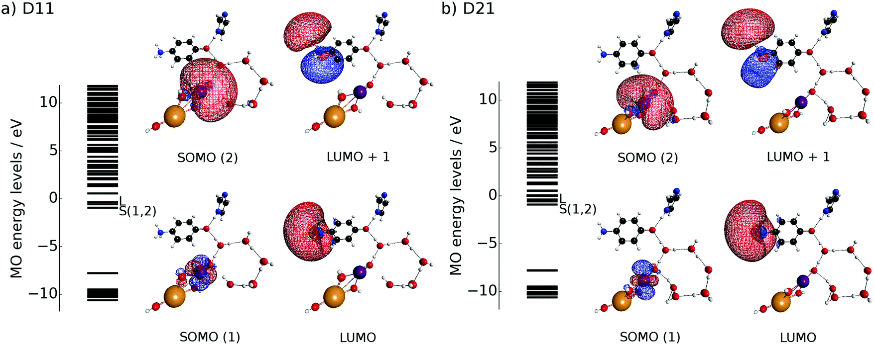 | ||
| Fig. 9 Spatial distribution of the frontier MOs of the initial geometry for (a) D11 and (b) D21. Each geometry can be regarded as a subsystem of Kn, in which n = 0 or 1 for D11 and n = 2 or 3 for D21. | ||
Because the results for D11 and D21 are qualitatively the same as each other, we will first explain the results for D11, and briefly discuss D21 later. Let us track the electron dynamics associated with the H2 and H3 relay-transfer. Recall that the H1 transfer had already occurred in the ground state, which is regarded as one of the proton transfers of the relay. In Fig. 10a, we show selected snapshots of the spatial distribution of the unpaired electron density D(r) for D11, which is defined as follows:67
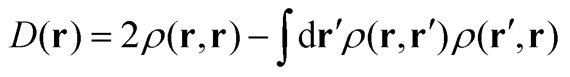 | (14) |
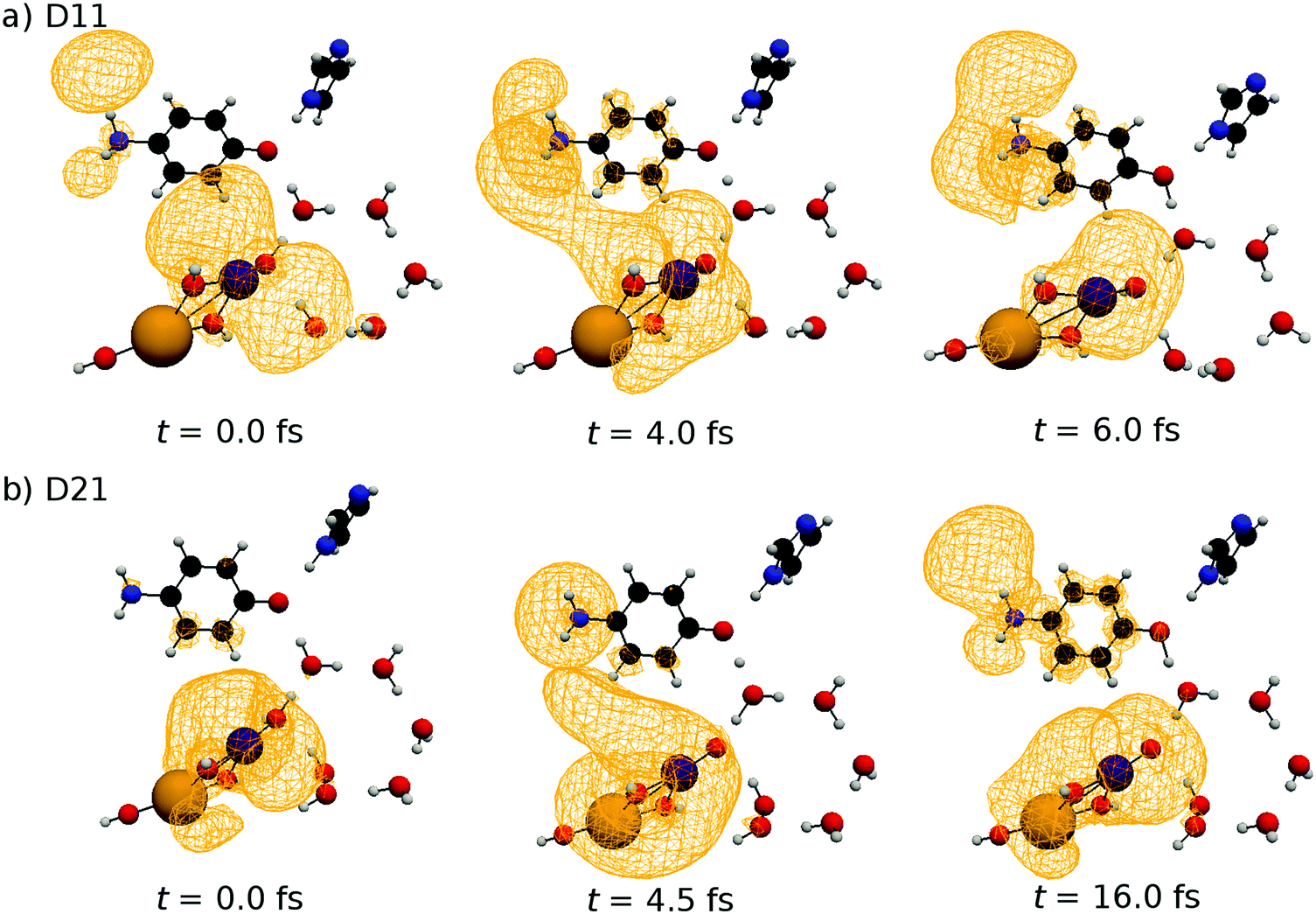 | ||
| Fig. 10 Selected snapshots of the spatial distribution of the unpaired electron density D(r) (yellow contour mesh) along the photoexcited SET paths of D11 (a) and D21 (b). Color is assigned as follows: Mn = purple, Ca = orange, O = red, N = blue, C = black and H = gray. | ||
3.4 Energy profile for the series of reactions
We next survey the feasibility of the chemical reactions involved in the catalytic cycle from the view point of the energetics only. The computations of relevant chemical dynamics are prohibitively large in the present stage of our study, and it is also very difficult to faithfully track the reaction coordinates in so many dimensional complicated reactions. For the same reason, studies to identify mechanisms such as the coherent dynamics, concerted reactions, or thermal processes were not performed. Instead we only picked up key molecular configurations and examined their energy profile in terms of the standard quantum chemistry.When the system starts from the configuration of K0, its first group is 3[D11] (D11 in structure and triplet in spin). The second group consisted of EBf–e−, PBf–H+, 4XEA, 4XPA, and 2H2O. In other words, the second group had two water molecules, the buffers with an electron and a proton, and the empty external proton and electron acceptors (see Fig. 2). After the CPEWT and the electron abstraction from the Rydberg-like states of the EA, the system changes to K02. The first group becomes 2[D12]+, and one of the XEAs accepts the electron from the first group, that is, 4XEA + e− → 3XEA + XEA–e−. In this way, we can define the system components to draw an energy profile corresponding to the reaction scheme.
Several spin states of product combinations of K35 ([D11]) and oxygen molecule are possible quantum mechanically in the final stage of the series of reactions, even though the initial spin state of K0 is triplet. For instance, the spin combinations 3[D11] + 3O2, 1[D11] + 3O2, 3[D11] + 1O2 are allowed starting from 3K0, depending on the energy available, where 3[D11] indicates the triplet of D11. Obviously, 3[D11] + 3O2 is the lowest in energy and brings the system back to 3K0. However, due to the limitation of the computational capacity available, we actually computed a little higher energy channel to 1[D11] + 3O2. We thus defined the K0′ state, which is a spin singlet state corresponding to the triplet K0. It includes 1[D11] and 3O2. See Section S2 (ESI†) for further details of the energy profile estimation.
We had ten types of the first group labeled Dnm (n = 1 or 2 and m = 1, 2, 3, 4 or 5), as shown in Fig. 8. D1m appears in K0–K1 and K1–K2 transitions, whereas D2m appears in K2–K3 and K3–K0 transitions. The major difference between D1m and D2m lies in that H2O2 is included in the EPR in D2m but not in that of D1m. We estimated the energy of the first group for Dnm with the open-shell RHF level of calculation after geometry optimization except for 1[D11].
As for the second group, its constituent molecules have not yet been explicitly specified. This is because we have thus far discussed only the functionality of components like EBf and PBf acting in the photocatalytic cycle. To examine the energetics of the second group, we here dare to specify possible molecular species as appropriate candidates for the EBf and PBf. It seems natural to consider the energy profiles of redox reactions of 4-methylphenol as a model of tyrosine since it is used to store and carry electrons and protons in biochemical systems,39–41 suggesting that the energy range involved in the water-splitting cycle should also be suitable for the present model system. Thus we estimated the energy difference between XEA and XEA–e− from the following simple case, namely, the reaction of the 4-methylphenyl radical and 4-methylphenyl anion:
| CH3–C6H4–O + e− → [CH3–C6H4–O]− | (15) |
| [CH3–C6H4–O]− + H+ → CH3–C6H4–OH | (16) |
For the proton and/or electron exchange between the first and second groups, we only considered the energy changes to assess whether such a reaction is energetically possible or not, and we did not explicitly consider the mechanism of proton and/or electron exchange between the first and second groups. Incidentally, we have studied the reaction between the 3-methylindolyl radical and 3-methylindole as a model of tryptophan as another candidate of the above redox reactions and found that a wider energy range is needed to materialize water-splitting in the present cycle.
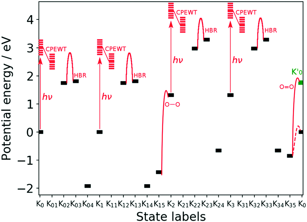 | ||
| Fig. 11 Energy of the key stages designated by Knm of the reaction scheme. “hν”, “HBR”, “O–O”, and “OO” denote the photoexcitation, hydrogen-bond reorganization, and O–O bond formation as H2O2, and the OO bond formation as O2, respectively. The barrier heights of the HBR are estimated to be at most 1.22 eV for K02 → K03 and 1.16 eV for K22 → K23. Those for K12 → K13 and K32 → K33 are the same as those for K02 → K03 and K22 → K23, respectively. The energy of Knm is that before the next process begins on it. For instance the energy of K04 (see Fig. 4) does not contain the energy required for protonation and electron-attachment to take place on it next. See text for the definition of K0′ that is colored in green. The dashed line connecting K35 and K0 is a possible pathway without singlet intermediates, not going to K0′. | ||
The energy profile can be divided into four parts, in which each corresponds to the Kn–Kn+1 transition and starts with photoexcitation followed by CPEWT. The final reaction is OO bond formation, the mechanism of which will be further studied below. The energy of the resulting system K0′ is not equal to that of K0. The difference originates from the spin multiplicity; K0 is in the spin triplet state and ends up in singlet state as K0′ after releasing a triplet oxygen molecule. It can be seen that the stable intermediates expressed as black bars in this figure lie in the range of −2 eV to +3 eV. We did not find a state with extremely high or low energy. As far as the photon energy (∼3 eV) and energies of the metastable intermediates are concerned, we may say that this water-splitting cycle is possible.
3.5 O![[double bond, length as m-dash]](https://www.rsc.org/images/entities/h3_char_e001.gif) O bond formation to reduce the Mn oxides
O bond formation to reduce the Mn oxides
Now let us discuss the mechanism of triplet O2 generation via the formation of H2O2. As will be demonstrated below, the mechanism of the OO (as in O2) and O–O (as in H2O2) bond formations are similar to each other. First we recall that both the reactant and product have been shown in the Kn5–Kn6 transitions in Section 2, in which n = 1 and n = 3 for O–O (Fig. 5) and OO (Fig. 7), respectively. Here we seek a deeper insight into the mechanism through a qualitative analysis of the electronic states. The present model asserts that they are both born from the water cluster and are associated with the reduction of the Mn oxide in such a way to make the next CPEWT possible. Since it is very difficult and time-consuming to carry out dynamical calculations, we instead tracked the evolution of the ground-state properties along an appropriate proton-transfer coordinate leading to O–O/OO bond formations.
We employed the CISD/RHF (triplet) level of calculation for the electrically neutral subsystem consisting of the EPD and a part of the EPR that is necessary for O–O/OO bond formation. The CISD active space was chosen as follows: (HOMO−9)–HOMO and two SOMOs were set to be the active occupied MOs, whereas the LUMO was the active virtual MO. This active space including the p and d orbitals of the O and the Mn atoms, respectively, can qualitatively describe the change of electronic states enough to clarify the mechanism of the O–O/OO bond formations.
O bond formation.
We illustrate the mechanism of triplet O2 generation by using a set of constraint-optimized geometries of the subsystem. Because of the similarity of the bond formation mechanism of O–O and OO, we first discuss the O–O bond formation and will mention the mutual differences later. A typical case of proton transfer to the EPD is discussed first. Other possible mechanisms have been examined, including simultaneous proton transfer and O–O bond formation, and these reaction pathways turned out to need significantly higher energy barriers than the present mechanism.
We concentrated on the four atoms of the subsystem to consider the mechanism. They are indicated by blue circles in Fig. 12a. The leftmost configuration is an excerpt of the essential subsystem of K15 (see Fig. 5). The subsystem itself was optimized beforehand, and no significant difference from the original one in K15 was found. As for the first reaction (proton transfer), the H atom in H2O that is doubly circled in the leftmost panel is forced to almost linearly shift to the EPD site so that the OH bond length is shortened down to 1.0 Å, which is the typical OH bond length. The other three circled atoms are fixed in space while this reaction, and the other atoms are optimized. This is therefore a constrained geometry optimization. By this proton shift, the molecular configuration becomes as shown in the central panel of Fig. 12a. The spatial distribution of the unpaired electron density does not significantly change in this reaction, that is, the subsystem remains in a biradical state.
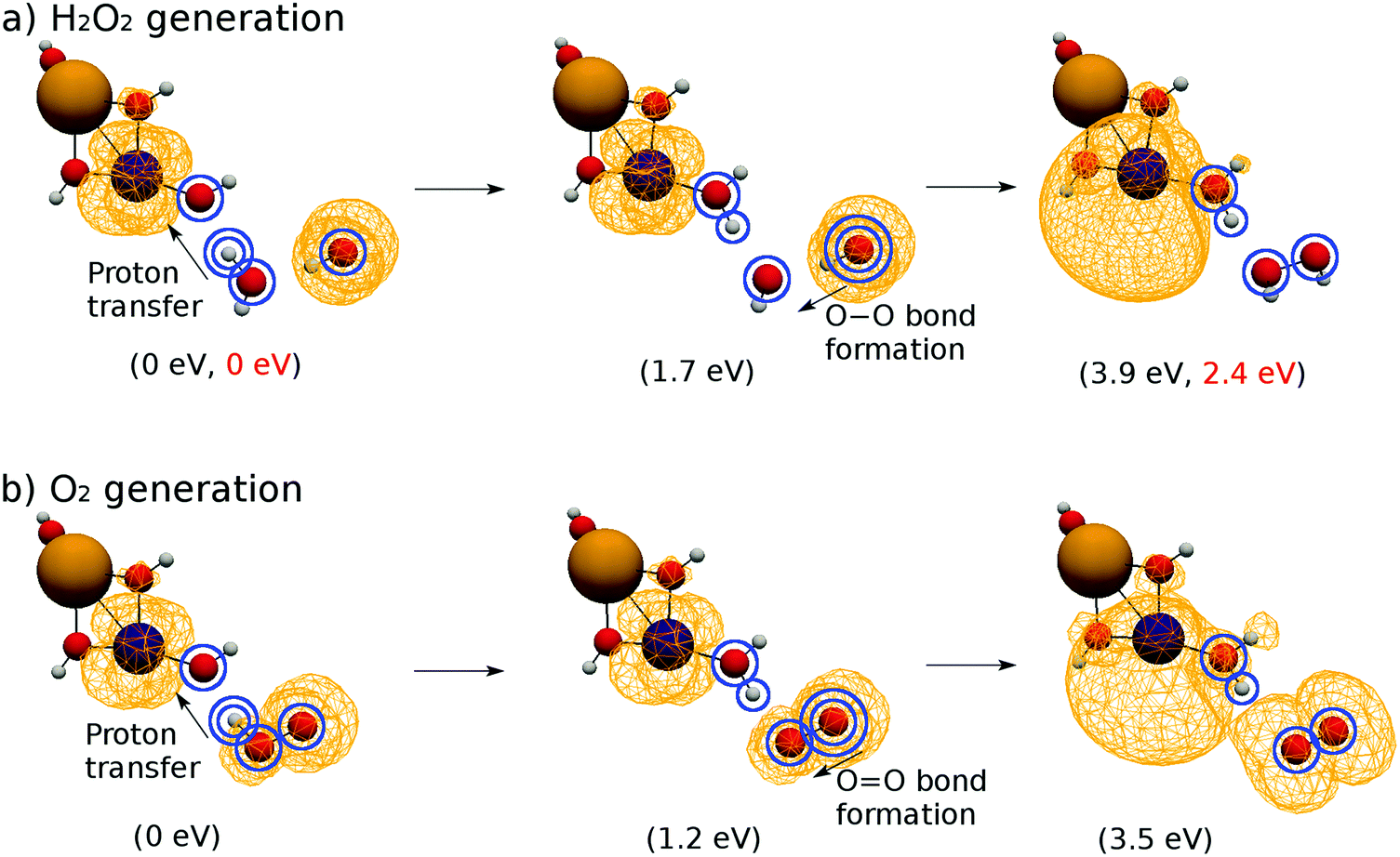 | ||
| Fig. 12 Spatial distribution of the unpaired electron density relevant to the bond formation of (a) H2O2 and (b) O2. The leftmost figures are optimized normally, and the center and rightmost figures depict the constraint-optimized geometry. The values in the parentheses in black beneath each snapshot denote the energy difference from the initial state, whereas the values in red show similar quantities except that the system is surrounded by 20 water molecules as a solvent. | ||
Next the O atom of the OH radical that is doubly circled in the central panel is shifted to the O atom of the other OH that has been created by the first proton transfer. Hence, the OO bond length is shortened to 1.5 Å, which is the typical O–O bond length of H2O2. This approach of two oxygen atoms results in the geometry in the rightmost panel of Fig. 12a. The exceeding electron for H2O2 is transferred to the EPD, oxidizing the EPR, which is seen as the unpaired electron density localizing on the EPD as shown in the rightmost panel of Fig. 12a.
The energy increases rather monotonically from the left configuration to the right one in the panel of Fig. 12a, the barrier of which amounts up to about 3.9 eV. This energy difference is higher than the energy profile shown in Fig. 11, which is equal to 3.0 eV. This difference mainly comes from the way of calculation in Fig. 12a, which represents the calculation under constrained geometry optimization with naked (gas phase) reaction disregarding the presence of the solvent water molecules (see the electronic energy for each configuration in the parentheses in Fig. 12). In fact, the generated HOOH should actually be stabilized by hydrogen bonds as shown in K2 of Fig. 5. It is therefore natural to conceive that this series of reactions takes place cooperatively in the solvation dynamics being surrounded by abundant water molecules. Indeed, if we add many more water molecules (actually about 20 molecules) such that three water molecules reside surrounding the relevant H2O2, the energy barrier lowers to 2.4 eV with no change of the terminal electronic states (see the values in red in the parentheses in Fig. 12a). Therefore, this reaction can take place within the energy range of the ±3 eV.
The pathway of OO bond formation is implemented similarly to that of O–O bond formation (see Fig. 12b), but the minimum OO bond length is employed as 1.2 Å, which is the typical length for molecular oxygen in the triplet state. The energy barrier for the subsystem is about 3.6 eV, which is slightly less than that of the O–O bond formation. The proton and electron transfers occur in the same manner to reduce the EPD, but their spin distributions are totally different from each other as shown in the rightmost panels of Fig. 12a and b, which is discussed below.
O bond formations.
The O–O and OO bond formations are quite similar to each other except in one important aspect of spin multiplicity. As seen in Fig. 12, both reactions begin from biradical states, in which the unpaired electrons are located mainly on both the EPD and EPR sites. However, in the O–O bond formation the unpaired electrons are transferred to the EPD site to restore the localized triplet biradical state (see the rightmost panel of Fig. 12). The number of unpaired electrons is about 2.0. On the other hand, the OO bond formation ends up with its unpaired electron distribution found on both the EPD and the EPR sides (see the rightmost panel of Fig. 12b). The number of unpaired electrons is thus about 4.0 (2.0 on each). Analysis on the spin distribution shows that this tetra-radical state represents triplet O2 and the triplet (or even the singlet) biradical EPD simultaneously. This is one of the pathways of triplet O2 generation from singlet water molecules.
4 Concluding remarks
In terms of the dynamics and energetics of small Mn-oxides surrounded and contacted by hydrogen-bonding networks of water molecules, we have proposed a novel mechanism of the water-splitting photocatalytic cycle triggered by coupled proton electron-wavepacket transfer (CPEWT) to induce charge separation and have shown that the system is indeed feasible from the view point of energetics. This mechanism is a four-photon process from which a triplet O2 molecule emerges via the temporal formation of HOOH in the water cluster. We theoretically constructed a reaction scheme of the water-splitting cycle based on the characteristics of the CPEWT and the theoretically estimated energy profile, thereby showing that all of the metastable intermediates lie in the energy range of ±2.5 eV. Since each photon absorbed in the process of CPEWT has an energy of approximately 3 eV, the water-splitting cycle can be judged to be feasible.In the present scheme the Mn-oxides are supposed to be directly photoexcited up to an electronic manifold in which proton transfer causes nonadiabatic electron wavepacket transfer through pathways different from each other, thereby resulting in charge separation in the acceptors.3–5 This physical assumption may not be applied to the dynamics in PSII, which is widely conceived to take place in the electronic ground state.1,2 Therefore the present study is concerned with the very basic mechanism of photocatalysts and may be useful for designing artificial water splitting and/or solar cells. In this study of photodynamics, it has been positively confirmed that the CPEWT dynamics can take place even in the presence of hydrogen-bonding networks and also in the spin triplet state. As a result, it has been shown that triplet O2 can be generated from water clusters via H2O2 as an intermediate. It turns out that none of the oxygen atoms of the catalytic center MnCaO4H5 are directly involved in the OO bond formation.
Before closing this paper, let us briefly mention the implication of the difference between our proposed mechanism of O2 generation and that proposed by Siegbahn68 and other experimentalists69,70 studying Mn4CaO5 involved in PSII. The latter is summarized in that O2 is formed by breaking one of the μ-oxo bridges of the Mn cluster without tentative generation of peroxide (HOOH) (as for the possible formation of peroxides in the moiety of PSII, see ref. 71–74.) Besides, it is widely believed that virtually all plants and cyanobacteria carrying out photosynthesis resort exclusively to Mn4CaO5 as the central catalyst.75 These studies on Mn4CaO5 raise a naive question about evolution at the molecular level, since it is hard to imagine that such a highly sophisticated cluster and mechanism appeared all of sudden in the evolutionary process of biological systems (allegedly 2.5 billion years ago76,77). It is quite likely that simpler and less sophisticated photocatalysts were used by biological systems on the way to the goal of the current biological status resting on Mn4CaO5. Not only the evolution of catalysts but the composition of the air on the earth should be different from what we have now in that the amount of oxygen should have been far less and consequently the distribution of the wavelength of the sunlight to the earth surface must have been shifted to the ultraviolet region. All of these factors suggest that photocatalytic cycles in the wilder and immature circumstances of mother nature should have used smaller Mn oxides and simpler mechanisms for charge separation and giving birth to oxygen molecules directly from bulk water before the biological systems finally attained Mn4CaO5.
From the view point of artificial water splitting technology, an appropriate choice of electron buffer and proton buffer can be crucial to determine the efficiency of splitting. In this paper we tentatively assigned the 4-methylphenyl radical as a candidate of the electron buffer, and the 4-methylphenyl anion as that of the proton buffer. In this regard, another comparison between our proposed photocatalytic system basically with MnCaO4H5 and Mn4CaO5 in PSII suggests that the roles of electron buffer necessary for the regulation of charge and spin multiplicity are achieved in a sophisticated manner by the presence of multiple Mn atoms in Mn4CaO5. This aspect will be discussed in the future.
Finally, one of the most difficult aspects in charge separation dynamics in water splitting by PSII is the widely accepted assumption that it can take place in the electronic ground state.1,2 This is not a matter of biological assumption but is about chemical principle. In our next paper we will discuss the possibility of ground-state CPEWT in Mn oxides and accepters, a charge separation which is induced by collision with an external chromophore.
Conflicts of interest
There are no conflicts of interest to declare.Acknowledgements
This work was supported in part by a Grant-in-Aid for Scientific Research from the Ministry of Education and Science in Japan (15H05752).References
- D. Voet and J. G. Voet, Biochemistry, John Wiley, New Jersey, 4th edn, 2011 Search PubMed.
- J. M. Berg, J. L. Tymoczko and L. Stryer, Biochemistry, Freeman, New York, 5th edn, 2002 Search PubMed.
- K. Yamamoto and K. Takatsuka, ChemPhysChem, 2015, 16, 2534–2537 CrossRef CAS PubMed.
- K. Yamamoto and K. Takatsuka, Chem. Phys., 2016, 475, 39–53 CrossRef CAS.
- K. Yamamoto and K. Takatsuka, ChemPhysChem, 2017, 18, 537–548 CrossRef CAS PubMed.
- H. Ushiyama and K. Takatsuka, Angew. Chem., 2007, 119, 593–596 CrossRef.
- S. Hammes-Schiffer, Chem. Rev., 2010, 110, 6937–6938 CrossRef CAS PubMed.
- S. Hammes-Schiffer and A. A. Stuchebrukhov, Chem. Rev., 2010, 110, 6939–6960 CrossRef CAS PubMed.
- M. H. V. Huynh and T. J. Meyer, Chem. Rev., 2007, 107, 5004–5064 CrossRef CAS PubMed.
- O. Tishchenko, D. G. Truhlar, A. Ceulemans and M. T. Nguyen, J. Am. Chem. Soc., 2008, 130, 7000–7010 CrossRef CAS PubMed.
- S. Hammes-Schiffer and A. V. Soudackov, J. Phys. Chem. B, 2008, 112, 14108–14123 CrossRef CAS PubMed.
- P. E. Siegbahn and M. R. Blomberg, Chem. Rev., 2010, 110, 7040–7061 CrossRef CAS PubMed.
- S. Hammes-Schiffer, J. Phys. Chem. Lett., 2011, 2, 1410–1416 CrossRef CAS.
- D. R. Weinberg, C. J. Gagliardi, J. F. Hull, C. F. Murphy, C. A. Kent, B. C. Westlake, A. Paul, D. H. Ess, D. G. McCafferty and T. J. Meyer, Chem. Rev., 2012, 112, 4016–4093 CrossRef CAS PubMed.
- J. P. Layfield and S. Hammes-Schiffer, Chem. Rev., 2014, 114, 3466–3494 CrossRef CAS PubMed.
- A. L. Sobolewski and W. Domcke, J. Phys. Chem. A, 2001, 105, 9275–9283 CrossRef CAS.
- A. Sobolewski, W. Domcke, C. Dedonder-Lardeux and C. Jouvet, Phys. Chem. Chem. Phys., 2002, 4, 1093–1100 RSC.
- A. L. Sobolewski and W. Domcke, J. Phys. Chem. A, 2007, 111, 11725–11735 CrossRef CAS PubMed.
- A. L. Sobolewski and W. Domcke, J. Phys. Chem. A, 2008, 112, 7311–7313 CrossRef CAS PubMed.
- A. Carrera, I. Nielsen, P. Carcabal, C. Dedonder, M. Broquier, C. Jouvet, W. Domcke and A. Sobolewski, J. Chem. Phys., 2009, 130, 024302 CrossRef CAS PubMed.
- R. Borrelli and W. Domcke, Chem. Phys. Lett., 2010, 498, 230–234 CrossRef CAS.
- R. Borrelli, M. Thoss, H. Wang and W. Domcke, Mol. Phys., 2012, 110, 751–763 CrossRef CAS.
- A. L. Sobolewski and W. Domcke, Chem. Phys. Lett., 2009, 479, 144–148 CrossRef CAS.
- A. L. Sobolewski and W. Domcke, Phys. Chem. Chem. Phys., 2012, 14, 12807–12817 RSC.
- T. N. Karsili, D. Tuna, J. Ehrmaier and W. Domcke, Phys. Chem. Chem. Phys., 2015, 17, 32183–32193 RSC.
- X. Liu, A. L. Sobolewski, R. Borrelli and W. Domcke, Phys. Chem. Chem. Phys., 2013, 15, 5957–5966 RSC.
- X. Liu, A. L. Sobolewski and W. Domcke, J. Phys. Chem. A, 2014, 118, 7788–7795 CrossRef CAS PubMed.
- X. Liu, T. N. Karsili, A. L. Sobolewski and W. Domcke, J. Phys. Chem. B, 2015, 119, 10664–10672 CrossRef CAS PubMed.
- X. Liu, T. N. Karsili, A. L. Sobolewski and W. Domcke, Chem. Phys., 2016, 464, 78–85 CrossRef CAS.
- J. Ehrmaier, T. N. Karsili, A. L. Sobolewski and W. Domcke, J. Phys. Chem. A, 2017, 121, 4754–4764 CrossRef CAS PubMed.
- J. Ehrmaier, D. Picconi, T. N. Karsili and W. Domcke, J. Chem. Phys., 2017, 146, 124304 CrossRef PubMed.
- X. Wu, T. N. Karsili and W. Domcke, Molecules, 2017, 22, 135 CrossRef PubMed.
- W. Domcke, D. Yarkony and H. Köppel, Conical Intersections: Electronic Structure, Dynamics & Spectroscopy, World Scientific, Singapore, 2004, vol. 15 Search PubMed.
- B. A. Barry, U. Brahmachari and Z. Guo, Acc. Chem. Res., 2017, 50, 1937–1945 CrossRef CAS PubMed.
- B. Kok, B. Forbush and M. McGloin, Photochem. Photobiol., 1970, 11, 457–475 CrossRef CAS PubMed.
- P. Joliot, Photosynth. Res., 2003, 76, 65–72 CrossRef CAS PubMed.
- M.-T. Zhang and L. Hammarström, J. Am. Chem. Soc., 2011, 133(23), 8806–8809 CrossRef CAS PubMed.
- K. Takematsu, H. Williamson, A. M. Blanco-Rodrguez, L. Sokolová, P. Nikolovski, J. T. Kaiser, M. Towrie, I. P. Clark, A. Vlcék Jr and J. R. Winkler, et al. , J. Am. Chem. Soc., 2013, 135, 15515–15525 CrossRef CAS PubMed.
- A. Migliore, N. F. Polizzi, M. J. Therien and D. N. Beratan, Chem. Rev., 2014, 114, 3381–3465 CrossRef CAS PubMed.
- H. B. Gray and J. R. Winkler, Proc. Natl. Acad. Sci. U. S. A., 2015, 112, 10920–10925 CrossRef CAS PubMed.
- A. M. Bogdanov, A. Acharya, A. V. Titelmayer, A. V. Mamontova, K. B. Bravaya, A. B. Kolomeisky, K. A. Lukyanov and A. I. Krylov, J. Am. Chem. Soc., 2016, 138, 4807–4817 CrossRef CAS PubMed.
- H.-D. Meyer and W. H. Miller, J. Chem. Phys., 1979, 70, 3214–3223 CrossRef CAS.
- D. A. Micha, J. Chem. Phys., 1983, 78, 7138–7145 CrossRef CAS.
- A. Garca-Vela, R. Gerber and D. Imre, J. Chem. Phys., 1992, 97, 7242–7250 CrossRef.
- W. H. Miller, Faraday Discuss., 1998, 110, 1–21 RSC.
- M. D. Hack, A. W. Jasper, Y. L. Volobuev, D. W. Schwenke and D. G. Truhlar, J. Phys. Chem. A, 2000, 104, 217–232 CrossRef CAS.
- K. Takatsuka, J. Phys. Chem. A, 2007, 111, 10196–10204 CrossRef CAS PubMed.
- T. Yonehara and K. Takatsuka, J. Chem. Phys., 2008, 129, 134109 CrossRef PubMed.
- T. Yonehara, K. Hanasaki and K. Takatsuka, Chem. Rev., 2012, 112, 499–542 CrossRef CAS PubMed.
- K. Takatsuka, T. Yonehara, K. Hanasaki and Y. Arasaki, Chemical Theory Beyond the Born-Oppenheimer Paradigm: Nonadiabatic Electronic and Nuclear Dynamics in Chemical Reactions, World Scientific, Singapore, 2015 Search PubMed.
- T. Yonehara and K. Takatsuka, J. Chem. Phys., 2008, 128, 154104 CrossRef PubMed.
- T. Yonehara, S. Takahashi and K. Takatsuka, J. Chem. Phys., 2009, 130, 214113 CrossRef PubMed.
- T. Yonehara and K. Takatsuka, Chem. Phys., 2009, 366, 115–128 CrossRef CAS.
- T. Yonehara and K. Takatsuka, J. Chem. Phys., 2010, 132, 244102 CrossRef PubMed.
- K. Takatsuka and T. Yonehara, Phys. Chem. Chem. Phys., 2011, 13, 4987–5016 RSC.
- K. Takatsuka and T. Yonehara, Adv. Chem. Phys., 2010, 144, 93–156 CrossRef CAS.
- T. Yonehara and K. Takatsuka, J. Chem. Phys., 2012, 137, 22A520 CrossRef PubMed.
- T. Yonehara and K. Takatsuka, J. Phys. Chem. A, 2013, 117, 8599–8608 CrossRef CAS PubMed.
- K. Yamamoto and K. Takatsuka, J. Chem. Phys., 2014, 140, 124111 CrossRef PubMed.
- H. Ichikawa and K. Takatsuka, J. Phys. Chem. A, 2016, 121, 315–325 CrossRef PubMed.
- K. Takatsuka, J. Chem. Phys., 2017, 146, 084312 CrossRef PubMed.
- T. Matsuoka and K. Takatsuka, J. Chem. Phys., 2017, 146, 134114 CrossRef PubMed.
- W. J. Stevens, M. Krauss, H. Basch and P. G. Jasien, Can. J. Chem., 1992, 70, 612–630 CrossRef CAS.
- K. Nagashima and K. Takatsuka, J. Phys. Chem. A, 2012, 116, 11167–11179 CrossRef CAS PubMed.
- M. W. Schmidt, K. K. Baldridge, J. A. Boatz, S. T. Elbert, M. S. Gordon, J. H. Jensen, S. Koseki, N. Matsunaga, K. A. Nguyen, S. Su, T. L. Windus, M. Dupuis and J. A. Montgomery, J. Comput. Chem., 1993, 14, 1347–1363 CrossRef CAS.
- M. S. Gordon and M. W. Schmidt, Theory and applications of computational chemistry: the first forty years, Elsevier, Amsterdam, 2005 Search PubMed.
- K. Takatsuka, T. Fueno and K. Yamaguchi, Theor. Chim. Acta, 1978, 48, 175–183 CrossRef CAS.
- P. E. Siegbahn, Acc. Chem. Res., 2009, 42, 1871–1880 CrossRef CAS PubMed.
- M. Suga, F. Akita, M. Sugahara, M. Kubo, Y. Nakajima, T. Nakane, K. Yamashita, Y. Umena, M. Nakabayashi, T. Yamane, T. Nakano, M. Suzuki, T. Masuda, S. Inoue, T. Kimura, T. Nomura, S. Yonekura, L.-J. Yu, T. Sakamoto, T. Motomura, J.-H. Chen, Y. Kato, T. Noguchi, K. Tano, Y. Joti, T. Kameshima, T. Hatsui, E. Nango, R. Tanaka, H. Naitow, Y. Matsuura, A. Yamashita, M. Yamamoto, M. Yabashi, T. Ishikawa, S. Iwata and S. Jian-Ren, Nature, 2017, 543, 131–135 CrossRef CAS PubMed.
- I. D. Young, M. Ibrahim, R. Chatterjee, S. Gul, F. D. Fuller, S. Koroidov, A. S. Brewster, R. Tran, R. Alonso-Mori, T. Kroll, T. Michels-Clark, H. Laksmono, R. G. Sierra, C. A. Stan, R. Hussein, M. Zhang, L. Douthit, M. Kubin, C. de Lichtenberg, L. Vo Pham, H. Nilsson, M. H. Cheah, D. Shevela, C. Saracini, M. A. Bean, I. Seuffert, D. Sokaras, T.-C. Weng, E. Pastor, C. Weninger, T. Fransson, L. Lassalle, P. Bräuer, P. Aller, P. T. Docker, B. Andi, A. M. Orville, J. M. Glownia, S. Nelson, M. Sikorski, D. Zhu, M. S. Hunter, T. J. Lane, A. Aquila, J. E. Koglin, J. Robinson, M. Liang, S. Boutet, A. Y. Lyubimov, M. Uervirojnangkoorn, N. W. Moriarty, D. Liebschner, P. V. Afonine, D. G. Waterman, G. Evans, P. Wernet, H. Dobbek, W. I. Weis, A. T. Brunger, P. H. Zwart, P. D. Adams, A. Zouni, J. Messinger, U. Bergmann, N. K. Sauter, J. Kern, V. K. Yachandra and J. Yano, Nature, 2016, 540, 453–457 CrossRef CAS PubMed.
- L. Rapatskiy, N. Cox, A. Savitsky, W. M. Ames, J. Sander, M. M. Nowaczyk, M. Rögner, A. Boussac, F. Neese, J. Messinger and W. Lubitz, J. Am. Chem. Soc., 2012, 134, 16619–16634 CrossRef CAS PubMed.
- W. Hillier and T. Wydrzynski, Photosynth. Res., 1993, 38, 417–423 CrossRef CAS PubMed.
- P. L. Fine and W. D. Frasch, Biochemistry, 1992, 31, 12204–12210 CrossRef CAS PubMed.
- B. K. Semin, L. N. Davletshina, K. N. Timofeev, I. I. Il'ya, A. B. Rubin and M. Seibert, Photosynth. Res., 2013, 117, 385–399 CrossRef CAS PubMed.
- J. Yano and V. Yachandra, Chem. Rev., 2014, 114, 4175–4205 CrossRef CAS PubMed.
- G. Dismukes, V. Klimov, S. Baranov, Y. N. Kozlov, J. DasGupta and A. Tyryshkin, Proc. Natl. Acad. Sci. U. S. A., 2001, 98, 2170–2175 CrossRef CAS PubMed.
- K. Sauer and V. K. Yachandra, Proc. Natl. Acad. Sci. U. S. A., 2002, 99, 8631–8636 CrossRef CAS PubMed.
Footnote |
| † Electronic supplementary information (ESI) available. See DOI: 10.1039/c7cp07171j |
| This journal is © the Owner Societies 2018 |