
A Ni-loaded, metal–organic framework–graphene composite as a precursor for in situ electrochemical deposition of a highly active and durable water oxidation nanocatalyst†
Mohamed H.
Hassan
 a,
Ahmed B.
Soliman
b,
Worood A.
Elmehelmey
a,
Arwa A.
Abugable
a,
Stavros G.
Karakalos
c,
Mady
Elbahri
b,
Abdou
Hassanien
d and
Mohamed H.
Alkordi
*a
a,
Ahmed B.
Soliman
b,
Worood A.
Elmehelmey
a,
Arwa A.
Abugable
a,
Stavros G.
Karakalos
c,
Mady
Elbahri
b,
Abdou
Hassanien
d and
Mohamed H.
Alkordi
*a
aCenter for Materials Science, Zewail City of Science and Technology, 12578, Giza, Egypt. E-mail: malkordi@zewailcity.edu.eg
bNanochemistry and Nanoengineering, School of Chemical Engineering, Department of Chemistry and Materials Science, Aalto University, Kemistintie 1, 00076 Aalto, Finland
cCollege of Engineering and Computing, Swearingen Engineering Center, University of South Carolina, Columbia, SC 29208, USA
dJozef Stefan Institute, Condensed Matter Physics Dept. (F5), 39 Jamova, Ljubljana 1000, Slovenia
First published on 31st October 2018
Abstract
A novel approach to construct a highly active and durable Ni(OH)2 nanoparticle/graphene hybrid electrocatalyst for the oxygen-evolution reaction (OER) is reported. This approach utilized the Ni-loaded, graphene-supported, Zr–carboxylate metal–organic framework (UiO-66-NH2-Ni@G) as a sacrificial pre-catalyst to engender the true catalyst in an electrochemical surface restructuring process. This has resulted in an exceptionally active (η10 = 0.38 V vs. RHE) and highly durable OER catalyst, and can potentially be employed as a viable facile alternative to the commonly utilized pyrolysis of MOFs, to access heterogenous catalysts for demanding electrochemically-promoted reactions.
The growing global demand for natural resources calls for responsible utilization of such resources to meet the needs of the growing population as well as to minimize the impact on our environment. In order to efficiently utilize abundant, clean, but otherwise intermittent solar energy, a number of energy storage strategies are actively being investigated.1,2 One of the most promising solutions is to store the electrical energy generated by photovoltaic cells into chemical energy, best represented by the water splitting approach.3 In order to effectively realize this dream, scientists are on a quest to develop new catalysts to facilitate the water oxidation reaction, also known as the oxygen evolving reaction (OER).3–5 Such a quest is actively being explored in the area of heterogeneous catalysis, where microporous solids have demonstrated unparalleled potential as supports and/or active catalysts.6,7 Among the different types of microporous solids,8 metal–organic frameworks (MOFs) demonstrate several desirable attributes due to their hybrid composition, enabling their reticular synthesis,9 the ability to effectively underline their structure–function relationships, and their being widely amenable to fine-tune their properties through post-synthetic modifications.10,11 Most recently, a number of reports have addressed heterogeneous electrochemical catalysis by MOFs through epitaxial growth of thin films on conductive substrates. This approach addressed the limited electrical conductivity of MOFs where charge transport is efficient enough within the deposited thin layer to allow for the targeted application without the need to alter the intrinsic electrical conductivity of the MOF.12–15 However, application of such catalysts remains limited to working conditions that retain the structural integrity of the deposited MOFs. Alternatively, the pyrolysis of MOFs emerged as a potential pathway to utilize the pre-ordered structure of MOFs to generate a large number of different metal or metal oxide nanoparticles on porous carbon, which can survive the harsh conditions encountered in some of the most demanding catalytic reactions.16,17
Herein, we describe a novel approach as an alternative to the commonly utilized pyrolysis of MOFs. In this approach, a Zr–carboxylate MOF (UiO-66-NH2)18 was constructed atop graphene nanoplates (G), subsequently metalated with Ni(II) ions, and finally utilized as a sacrificial microporous precursor to deposit Ni(OH)2–Zr(OH)4 on G in an electrochemical surface restructuring process, Scheme 1. Furthermore, our method describes a unique one-pot synthesis to prepare a MOF@G nanocomposite. Briefly, incorporating a suspension of G into the molecular precursors of UiO-66-NH2, under stirring and heating, resulted in uniform deposition of UiO-66-NH2 nanocrystals atop the G (UiO-66-NH2@G). Based on the amount of G used in the synthesis and the isolated dry weight of the composite, a MOF contribution of 67 wt% to the composite was calculated. Moreover, metalation of the UiO-66-NH2@G composite by Ni(II) ions was successfully attained through simple incubation in an acetonitrile solution of Ni(NO3)2 at 80 °C for 1 h.
 | ||
| Scheme 1 Representation of the MOF@G transformation into the active Ni-based OER catalyst. | ||
The SEM and TEM images of UiO-66-NH2-Ni@G, Fig. 1, demonstrated no phase segregation between the MOF and the G due to the homogenous and complete coverage of the G nanoplates by the MOF crystals (ca. 90–120 nm). The attainment of the pure phase of the targeted MOF was confirmed through X-ray powder diffraction (XRD) and Fourier-transform infrared spectroscopy (FTIR), in the ESI.† The characteristic C–N stretching absorption bands at 1257 and 1340 cm−1 were observed in the FTIR spectra of UiO-66-NH2 and its composite with G, Fig. S1 (ESI†).19 The XRD pattern recorded for UiO-66-NH2@G closely matched that for pristine UiO-66-NH2, Fig. S2 (ESI†), with an additional small and broad peak at 2θ = 26.4 characteristic of agglomerates of G sheets.20,21 The uniform deposition of the MOF atop G and the uniform loading with Ni were further confirmed by energy dispersive X-ray spectroscopy (EDX), Fig S3 (ESI†). The X-ray photoelectron spectroscopy (XPS) elemental analysis conducted on UiO-66-NH2@G and UiO-66-NH2-Ni@G revealed a Ni loading of ∼1 wt%. The detailed element scans for the MOF@G sample before and after Ni metallation are shown in Fig. S4 (ESI†). The N1s peaks for the pristine MOF@G sample indicated two chemical environments at 399.3 eV, characteristic of the aromatic primary amine,22 and a peak at 400.5 eV, which can be attributed to the protonated or H-bonded form.23 The N1s peaks for UiO-66-NH2-Ni@G clearly demonstrated the presence of nitrate ions (peak observed at 407.5 eV)24 along with a noticeable increase in the relative abundance of the pyrimidine N atoms at 400.5 eV. This observation indicates the formation of –NH2⋯Ni coordination and/or to H-bonds within the solid, potentially to the nitrate ions or Ni(II) species. The Ni2p scan indicated the presence of Ni2+ (2p3/2 peak observed at 856.3 eV) with a relatively higher BE as compared to NiO (expected major peak component at 854.7 eV)25 or Ni(OH)2 (expected at 855.8 eV),23 suggesting interactions with the surrounding nitrate counterions and/or the aromatic amine nitrogen atoms from UiO-66-NH2. The prepared composites were found to be microporous, Fig. S5 (ESI†), with calculated surface areas (SAs) using the Brunauer–Emmet–Teller (BET) model of 1103 m2 g−1 and 930 m2 g−1 for UiO-66-NH2@G and UiO-66-NH2-Ni@G, respectively. A noticeable step in the N2 sorption isotherm, at low partial pressure, is indicative of some structural defects due to missing linkers, generating larger pores inside the solids.
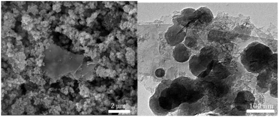 | ||
| Fig. 1 (Left) SEM image of UiO-66-NH2-Ni@G where all G sheets are uniformly coated with the MOF nanoparticles (one flake is evident at the center of the image resulting from sample grinding for imaging preparation) and (right) the TEM image of the composite. | ||
The electrochemical characterization studies of the UiO-66-NH2-Ni@G composite and three control samples (UiO-66-NH2@G, UiO-66-NH2-Ni, and Ni@G) were conducted. The cyclic voltammographs (CVs) for UiO-66-NH2-Ni@G demonstrated remarkable catalytic activity towards the OER, Fig. 2. The linear sweep voltammetry (LSV) for UiO-66-NH2-Ni@G indicated remarkably high catalytic activity (η10 = 0.37 V, Tafel slope of 45 mV dec−1), Fig. 2b, c and Table 1. The catalyst also demonstrated exceptional stability as shown in maintained catalytic current density under continuous electrolysis for 10 hours, Fig. 2d. This is in contrast to the three control samples, demonstrating no noticeable activity towards the OER, Fig. 2a and Fig. S6 (ESI†). This observation pointed out the significance of having all three components of the composite in order to observe the electrocatalytic activity. As the non-metalated MOF@G did not demonstrate noticeable catalytic activity, the possibility of catalytic activity originating solely from the Zr–carboxylate cluster, the organic linker, or the G sheets was ruled out. Furthermore, as the Ni-loaded MOF modified GCE did not demonstrate any catalytic activity, the crucial role of G sheets imbedded within the composite became evident. A plausible explanation for the observed activity in the ternary composite can then be ascribed to the facilitated electron transfer through the G nanoplates. The presence of Ni(II) ions in both UiO-66-NH2-Ni@G and UiO-66-NH2-Ni was confirmed by inspecting the CVs for the two solids, especially within the potential window pertinent to the Ni(II/III) redox couple around 1.4 V vs. RHE, Fig. 2a, indicative of the formation of the Ni(OOH) species.26,27 Comparing the CVs for UiO-66-NH2-Ni and UiO-66-NH2-Ni@G, an enhancement in the Ni(II/III) redox pair peak is evident and a concomitant enhancement of the water oxidation is observed as an anodic current wave in the latter. The G-supported composite demonstrated a pronounced peak at 1.39 V, for the Ni(II/III) redox transformation, with a cathodic shift of 30 mV as compared to the Ni(II/III) in UiO-66-NH2-Ni, indicative of facilitated charge transfer in the G-containing catalyst. Knowing that the UiO-66-NH2 MOF is unstable towards highly alkaline medium,28 the observed enhancement of OER catalytic activity upon increasing the number of CV scans, Fig. S7 (ESI†), with a visible loss of the material from the electrode surface indicated electrode surface restructuring, most likely deposition of Ni(OH)2 and Zr(OH)4 atop the G sheets, Ni(OH)2–Zr(OH)4@G. EDX analysis of the material after the catalytic run (conducted on an FTO electrode to avoid C interference by the GCE) indicated the presence of C, O, Zr, and Ni at the G flakes, Fig S8 and S9 (ESI†). Moreover, the composition of the active catalyst was attained through post-catalytic XPS analysis, Fig. 3. The O1s spectrum indicates the presence of four different O species: (1) oxygenated carbon species (533 eV), (2) those ascribed to Ni–OH/Ni–OOH/or C–OH (531.3 eV), (3) Zr(OH)4 (529.5 eV), and (4) bridging oxides of the type M–O–M′ (where M and M′ can be different or similar metal ions including Ni, Zr, and K) in agreement with proposed potassium ion intercalation (528.2 eV).29 The Zr2p peak indicated two environments for Zr, a minor component at 181 eV and a major one at 182.1 eV (Fig. S10, ESI†). This observation points towards the major formation of Zr(OH)4 rather than hydrous zirconia.30 The K2p spectrum indicated two peaks (291 and 292.1 eV) and can be assigned to two different coordination environments for K ions, potentially intercalated K within the Ni(OH)2, and those coordinated to Zr hydroxide. A TEM image after electrolysis, Fig. S11 (ESI†), indicated the formation of Ni(OH)2 nanoparticles (∼2.4 nm) with an observed interplanar distance of 0.24 nm that can be ascribed to the (101) plane of β-Ni(OH)231 or the (111) plane of α-Ni(OH)2.32 The existence of such separated Ni(OH)2 clusters was further confirmed by AFM spectroscopy through the phase imaging technique (Fig. S12, ESI†), and raise the possibility that the Ni(OH)2 cluster formation proceeded via the Volmer–Weber mechanism.33 In such proposed nucleation/growth, the cluster size and the binding mode with the G are expected to be the main factors governing the catalyst stability. Evidently, the MOF-derived Ni(OH)2 clusters on graphene exhibited a higher and more stable response than those formed conventionally via a co-precipitation method. This can be attributed to the superiority of the MOF degradation route as a control-releasing valve, which allows the MOF to regulate the flux of Ni(II) ions. The limited dosage of Ni(II) leached during MOF etching by the base became a limiting reagent that controlled the relative rates of both nucleation and the subsequent growth of the Ni(OH)2 clusters. Furthermore, since all the measurements were conducted in a stationary electrochemical cell setup, the catalyst grain formed will be concentrated within the GCE–solution interface. The presence of excess hydroxyl ions is then expected to leave the colloidal catalyst grains with a residual negative surface charge via selective adsorption of hydroxyl ions. Electrophoretic deposition of locally suspended catalyst grains then will be achieved while scanning the potential in the anodic region, leading to the build-up of a catalyst layer over the glassy carbon interface in an electrochemical activation process. The enhancement in activity seen here was also noticed previously and was ascribed to the conversion of β-Ni(OH)2 to β-NiOOH and finally to γ-NiOOH under electrochemical charge–discharge conditions.34 It is also possible to attribute the enhancement in activity upon cycling to the incorporation of trace Fe ions from the solution.35 To test this hypothesis of progressive electrode restructuring under the electrochemical measurement conditions, a sample of UiO-66-NH2-Ni@G was first treated with 1 M KOH, washed, and then cast on the GCE, demonstrating no catalytic activity towards the OER. This observation further supported the role of the electrochemical activation process through which the obtained true catalyst Ni(OH)2–Zr(OH)4@G was deposited on the GC electrode surface. In an attempt to further characterize the active catalyst through Raman spectroscopy, a sample was deposited and subjected to electrolysis on an FTO electrode, to avoid interference from the carbon background of the GCE. The D, G, and 2D bands characteristic of graphitic carbon materials are evident in the spectrum collected, Fig. 4, with noticeable changes in the ID/IG ratio between the G sheets and the Ni(OH)2–Zr(OH)4@G composite.38,39 The D band at ∼1370 cm−1, arising from a defect-induced breathing mode of sp2 rings, is much enhanced in the case of the Ni(OH)2–Zr(OH)4@G composite, as similarly observed in other G systems functionalized by nanoparticles,40 indicating smaller domains of the sp2 carbons. The ID/IG for the G is found to be 0.68, while that for the Ni(OH)2@G composite was found to be 0.99, suggesting a decrease in the IG value, indicating that the binding between Zr(OH)4 and Ni(OH)2 with G can be attributed to the direct chemical bond, most probably via the C–O–M bond, or to charge transfer interactions. Additionally, two Raman bands were observed at 480 cm−1 and 570 cm−1, which were previously ascribed to NiOOH generated through oxidation of Ni(OH)2.41
 | ||
| Fig. 2 (a) CV scans, with a magnified part of the CVs showing the Ni(II/III) redox couple in the inset, of UiO-66-NH2-Ni (blue trace), and UiO-66-NH2-Ni@G (red trace), demonstrating OER activity only for the latter; (b) LSV scan of UiO-66-NH2-Ni@G with a magnified image in the inset; (c) the Tafel plot with a linear fit for UiO-66-NH2-Ni@G and (d) the corresponding chronopotentiometry showing stability for 10 hours under continuous electrolysis. All measurements were recorded in 1 M KOH with a scan rate of 100 mV s−1 for CVs and 10 mV s−1 for LSV. | ||
| Catalyst | OER overpotential (η, V) | η@10 mA cm−2 | Ref. |
|---|---|---|---|
| a No ohmic drop compensation was implemented. b Manually extracted values from reported LSV plots. | |||
| UiO-66-NH2-Ni@G | 0.29 | 0.38 | This worka |
| CoPi | 0.4b | 0.42 | 3 |
| IrOx | 0.25 | 0.32 | 3 |
| NiCeOx | 0.35 | 0.43 | 3 |
| NiO nanoplates | 0.35 | 0.43 | 36 |
| NiOx | 0.35b | 0.42 | 3 |
| CoO | — | 0.45 | 37 |
 | ||
| Fig. 3 XPS detailed spectra of the catalyst after electrolysis in 1 M KOH. | ||
 | ||
| Fig. 4 Raman spectra of the G and the Ni(OH)2@G electrode material deposited on FTO and after 10 CV scans at 1 M KOH. | ||
The enhanced catalytic activity of the composite can be attributed to the interplay between its three components, the Zr(OH)4, Ni(OH)2, and G. Simply the catalyst formation starts with the deliberate disintegration of the MOF as a result of its chemical instability in the highly alkaline medium. This process is accompanied by the instantaneous precipitation of Ni(OH)2–Zr(OH)4@G (as confirmed by EDX and XPS analysis) within the electrode vicinity. Such a formed composite is attached to the electrode surface in an electrochemical activation process most probably via anodic electrophoretic deposition. It is demonstrated that the optimized combination of the catalyst's components, the oxophilicity of hydrous zirconia, the electrochemical activity of Ni(OH)2, and the electronic conductivity of G well contributed to the high activity and durability of the final catalyst. We envision a broader applicability of such a strategy to immobilize MOFs, in general, on several types of supports including, but not limited to, carbon nanotubes and 2D materials like metal sulfides and chalcogenides, and subsequent electrochemical surface reconstruction, with minimal variations to the conditions described herein. This strategy can thus prove useful to access numerous electrochemical processes including catalysis and sensing, where the rich chemistry of precursor MOFs can be exploited, designed, and further fine tuned to provide viable solutions to a number of demanding applications.
We acknowledge the financial support of Zewail City of Science and Technology (CMS-MA).
Conflicts of interest
There are no conflicts to declare.References
- H. B. Gray, Nat. Chem., 2009, 1, 7 CrossRef CAS.
- N. S. Lewis and D. G. Nocera, Proc. Natl. Acad. Sci. U. S. A., 2006, 103, 15729–15735 CrossRef CAS PubMed.
- C. C. McCrory, S. Jung, J. C. Peters and T. F. Jaramillo, J. Am. Chem. Soc., 2013, 135, 16977–16987 CrossRef CAS PubMed.
- Y. Hu, F. Li, Y. Long, H. Yang, L. Gao, X. Long, H. Hu, N. Xu, J. Jin and J. Ma, J. Mater. Chem. A, 2018, 6, 10433–10440 RSC.
- N. Han, K. R. Yang, Z. Lu, Y. Li, W. Xu, T. Gao, Z. Cai, Y. Zhang, V. S. Batista, W. Liu and X. Sun, Nat. Commun., 2018, 9, 924 CrossRef.
- P. Kaur, J. T. Hupp and S. T. Nguyen, ACS Catal., 2011, 1, 819–835 CrossRef CAS.
- A. B. Soliman, R. R. Haikal, Y. S. Hassan and M. H. Alkordi, Chem. Commun., 2016, 52, 12032–12035 RSC.
- R. R. Haikal, X. Wang, Y. S. Hassan, M. R. Parida, B. Murali, O. F. Mohammed, P. J. Pellechia, M. Fontecave and M. H. Alkordi, ACS Appl. Mater. Interfaces, 2016, 8, 19994–20002 CrossRef CAS PubMed.
- O. M. Yaghi, M. O'Keeffe, N. W. Ockwig, H. K. Chae, M. Eddaoudi and J. Kim, Nature, 2003, 423, 705–714 CrossRef CAS PubMed.
- S. J. Garibay, Z. Wang, K. K. Tanabe and S. M. Cohen, Inorg. Chem., 2009, 48, 7341–7349 CrossRef CAS.
- W. Morris, C. J. Doonan and O. M. Yaghi, Inorg. Chem., 2011, 50, 6853–6855 CrossRef CAS.
- Y. Kobayashi, B. Jacobs, M. D. Allendorf and J. R. Long, Chem. Mater., 2010, 22, 4120–4122 CrossRef CAS.
- S. Takaishi, M. Hosoda, T. Kajiwara, H. Miyasaka, M. Yamashita, Y. Nakanishi, Y. Kitagawa, K. Yamaguchi, A. Kobayashi and H. Kitagawa, Inorg. Chem., 2009, 48, 9048–9050 CrossRef CAS.
- I. Hod, O. K. Farha and J. T. Hupp, Chem. Commun., 2016, 52, 1705–1708 RSC.
- I. Hod, W. Bury, D. M. Gardner, P. Deria, V. Roznyatovskiy, M. R. Wasielewski, O. K. Farha and J. T. Hupp, J. Phys. Chem. Lett., 2015, 6, 586–591 CrossRef CAS PubMed.
- K. Shen, X. Chen, J. Chen and Y. Li, ACS Catal., 2016, 6, 5887–5903 CrossRef CAS.
- X. Wang, X. Huang, W. Gao, Y. Tang, P. Jiang, K. Lan, R. Yang, B. Wang and R. Li, J. Mater. Chem. A, 2018, 6, 3684–3691 RSC.
- M. J. Katz, Z. J. Brown, Y. J. Colon, P. W. Siu, K. A. Scheidt, R. Q. Snurr, J. T. Hupp and O. K. Farha, Chem. Commun., 2013, 49, 9449–9451 RSC.
- M. Sarker, J. Y. Song and S. H. Jhung, Chem. Eng. J., 2018, 331, 124–131 CrossRef CAS.
- G. Wang, J. Yang, J. Park, X. Gou, B. Wang, H. Liu and J. Yao, J. Phys. Chem. C, 2008, 112, 8192–8195 CrossRef CAS.
- J. Zhang, H. Yang, G. Shen, P. Cheng, J. Zhang and S. Guo, Chem. Commun., 2010, 46, 1112–1114 RSC.
- S. J. Kerber, J. J. Bruckner, K. Wozniak, S. Seal, S. Hardcastle and T. L. Barr, J. Vac. Sci. Technol., A, 1996, 14, 1314–1320 CrossRef CAS.
- M. S. Lee, M. Park, H. Y. Kim and S. J. Park, Sci. Rep., 2016, 6, 23224 CrossRef CAS.
- C. A. Tolman, W. M. Riggs, W. J. Linn, C. M. King and R. C. Wendt, Inorg. Chem., 1973, 12, 2770–2778 CrossRef CAS.
- A. P. Grosvenor, M. C. Biesinger, R. S. C. Smart and N. S. McIntyre, Surf. Sci., 2006, 600, 1771–1779 CrossRef CAS.
- J. C. B. Nadesan, J. Electrochem. Soc., 1985, 132, 2957 CrossRef CAS.
- L. Trotochaud, J. K. Ranney, K. N. Williams and S. W. Boettcher, J. Am. Chem. Soc., 2012, 134, 17253–17261 CrossRef CAS.
- M. Kandiah, M. H. Nilsen, S. Usseglio, S. Jakobsen, U. Olsbye, M. Tilset, C. Larabi, E. A. Quadrelli, F. Bonino and K. P. Lillerud, Chem. Mater., 2010, 22, 6632–6640 CrossRef CAS.
- M. Chigane and M. Ishikawa, J. Chem. Soc., Faraday Trans., 1998, 94, 3665–3670 RSC.
- C. Huang, Z. Tang and Z. Zhang, J. Am. Ceram. Soc., 2001, 84, 1637–1638 CrossRef CAS.
- Z. Wu, X. L. Huang, Z. L. Wang, J. J. Xu, H. G. Wang and X. B. Zhang, Sci. Rep., 2014, 4, 3669 CrossRef PubMed.
- H. Bode, K. Dehmelt and J. Witte, Z. Anorg. Allg. Chem., 1969, 366, 1–21 CrossRef CAS.
- H. Brune, in Encyclopedia of Materials: Science and Technology, ed. K. H. J. Buschow, R. W. Cahn, M. C. Flemings, B. Ilschner, E. J. Kramer, S. Mahajan and P. Veyssière, Elsevier, Oxford, 2001, pp. 3683–3692, DOI:10.1016/B0-08-043152-6/00657-4.
- S. Anantharaj, P. E. Karthik and S. Kundu, Catal. Sci. Technol., 2017, 7, 882–893 RSC.
- L. Trotochaud, S. L. Young, J. K. Ranney and S. W. Boettcher, J. Am. Chem. Soc., 2014, 136, 6744–6753 CrossRef CAS.
- X.-Y. Yu, Y. Feng, B. Guan, X. W. Lou and U. Paik, Energy Environ. Sci., 2016, 9, 1246–1250 RSC.
- S. Jung, C. C. L. McCrory, I. M. Ferrer, J. C. Peters and T. F. Jaramillo, J. Mater. Chem. A, 2016, 4, 3068–3076 RSC.
- A. C. Ferrari and J. Robertson, Phys. Rev. B: Condens. Matter Mater. Phys., 2000, 61, 14095–14107 CrossRef CAS.
- A. C. Ferrari and J. Robertson, Phys. Rev. B: Condens. Matter Mater. Phys., 2001, 64, 075414 CrossRef.
- K. Balasubramanian, L. Zuccaro and K. Kern, Adv. Funct. Mater., 2014, 24, 6348–6358 CrossRef CAS.
- Y. L. Lo and B. J. Hwang, Langmuir, 1998, 14, 944–950 CrossRef CAS.
Footnote |
| † Electronic supplementary information (ESI) available. See DOI: 10.1039/c8cc07120a |
| This journal is © The Royal Society of Chemistry 2019 |