 Open Access Article
Long-lived charge separation in dye–semiconductor assemblies: a pathway to multi-electron transfer reactions
Elin
Sundin
and
Maria
Abrahamsson
 *
*
Department of Chemistry and Chemical Engineering, Chalmers University of Technology, 412 96 Gothenburg, Sweden. E-mail: abmaria@chalmers.se
First published on 25th April 2018
Abstract
Solar energy has the potential of providing the world with clean and storable energy. In principle, solar fuels can be generated by light absorption followed by primary charge separation and secondary charge separation to reaction centres. However this comes with several challenges, including the need for long-lived charge separation and accumulation of several charges. This Feature Article focuses on how to achieve long-lived charge separation in dye sensitized semiconductor assemblies and the way towards multi-electron transfer through conduction band mediation, aiming at solar fuel generation. Herein, we discuss various examples of how the charge separated lifetime can be extended and potential ways of achieving one or multiple electron transfer in these assemblies.
Introduction
More than 99% of all renewable energy resources near the Earth's surface are available in the form of solar radiation. This shows the inherent promise of solar energy to be the key component of a future, sustainable energy system. This also implies that every single percent efficiency increase of direct conversion of solar energy will enhance the renewable energy potential by as much as the full potential of all other renewables. In other words, enhancing the solar energy conversion efficiency is a necessity for a sustainable future. In this context, it is important to realize that society, for the foreseeable future, will need sustainable and cheap electricity but also fuels. Thus, the research efforts need to address both these matters, the greatest current challenge being the breakthroughs needed to realize solar fuel generation in sustainable molecules and/or materials. While solar electricity and solar fuels have many challenges in common, there is a major difference between these two fields – fuel forming reactions require the transfer of more than one electron. This implies that highly reduced or oxidized states need to be formed, inferring long-lived charge separation as a necessity. Absorption of one photon however yields only a single electron–hole pair. One enduring problem is therefore how to accumulate multiple charges after consecutive absorption of photons and how to efficiently couple these to multi-electron catalysis. To solve this problem, as noted by Hammarström, design and production of assemblies that integrate light absorption with efficient and multiple electron transfer to catalysts is necessary.1Much effort has been invested in the synthesis and characterization of molecular and supramolecular assemblies, designed to mimic the natural photosynthesis that is indeed capable of multiple electron transfer reactions.2 Another approach that has been attracting a lot of interest recently is to use nanostructured semiconductors together with molecular catalysts in more or less elaborate assemblies (vide infra). The most studied semiconductors in this context are wide band gap semiconductors, since typically they are inert to photodegradation and even though only UV-light can be absorbed, dye sensitization enables the use of visible light.3–8 Undesired reactions of the valence band (VB) from direct band gap excitation can also be avoided using the dye sensitized approach.
This Feature Article focuses on how to achieve photo-induced long-lived charge separation in dye sensitized nanostructured photoelectrodes, based on wide bandgap semiconductors like tin dioxide (SnO2) and titanium dioxide (TiO2). Furthermore, the discussion is extended to include some brief examples of how these hybrid assemblies can be used for conduction band (CB) mediated single and multiple electron transfer, a field that has developed with inspiration from the dye sensitized solar cell research area. Where appropriate, this is contrasted to and compared with current efforts and achievements in molecular systems.
Solar energy conversion: the need for long-lived charge separation
Chemical conversion of solar energy into electricity or fuels starts with an initial photon absorption event, followed by a primary charge separation step. Following this charge separation, the electron is, in the solar cell case, transported to an external circuit.9,10 As mentioned above, fuel formation requires multiple charge transfer events; for example Photosystem II uses four electrons in the water oxidation process, and four electrons are needed to reduce CO2 to formaldehyde, six for reduction to methanol and eight in case the desired product is methane.1,2,11–15Thus, the primary charge separation must be followed by subsequent charge transfer events needed to generate catalytically active states, capable of fuel forming reactions. Consequently, it becomes important to prevent undesired back electron transfer reactions.
Importantly, product selectivity must also be considered. Ideally the reactions should yield one desired product in high yield, and not a multitude of compounds. These considerations taken together put high demands on the molecule or material that should perform the reactions. In short, a solar fuel assembly should
• Utilize the solar spectrum as efficiently as possible, i.e. absorb light over a large portion of the visible range of the solar spectrum
• Undergo fast initial charge separation in high yield, to prevent parasitic decay pathways of the photoexcited state, and be able to shuttle the charges to the active sites of the molecule or material
• Sustain a charge separated state over long enough time for the desired fuel forming chemistry to occur without any substantial photo-degradation
• Prevent undesired electron transfer events upon secondary excitation
• Facilitate multi-electron transfer events and accommodate the many charges needed to produce the catalytically active states needed for fuel formation
• Include catalysts that can perform selective catalysis, preferably generating only one desired product
Considering all the requirements listed above, it is evident that several non-trivial challenges exist. It highlights the need for properties typically associated with materials, as well as properties commonly ascribed to molecules.
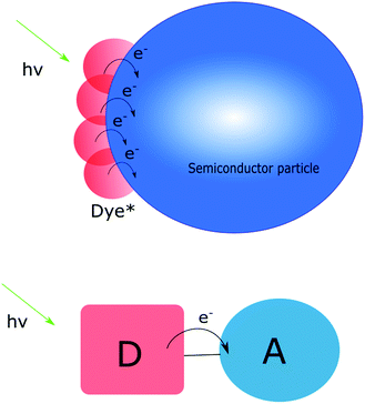
Typically, molecules bring tunability and selectivity to a charge transfer assembly. The benefit of these systems is therefore the ability to design and tune their properties in terms of e.g. light absorption and electronic coupling between donor and acceptor. However, for “simple” molecular assemblies like the one depicted in Fig. 1, the initial photoexcitation and charge separation must be repeated several times for multi-electron transfer to occur. This is challenging in terms of stability and competing back electron transfer reactions. In many cases a second excitation pulse can, instead of inducing a second electron transfer step, lead to undesired electron transfer events.16 These potential losses are important to keep in mind when designing photosensitizers for multi-electron transfer. It should be pointed out, however, that there are examples where two electrons have been accumulated on the acceptor following two excitation events.6 Furthermore, Yamamoto et al. have shown that covalently linking a molecular catalyst and an electron acceptor to a photosensitizer can yield water oxidation active supramolecular systems.17
An interesting and promising approach that has developed over the past decades is the design of systems focused on proton coupled electron transfer (PCET) where an electron transfer event is accompanied with a proton transfer event, thus compensating for the localization of charges.18–29 Using this approach, it becomes a matter of creating and sustaining redox equivalents rather than a highly reduced charge-separated state, thus addressing the stability problems often observed in highly reduced (or oxidized) molecules. It should also be noted that there are examples of molecular triads and even pentads that can sustain charge separation over very long times.18–23
Materials, such as wide bandgap semiconductors, on the other hand often lack the possibility to absorb visible light and while they can be very efficient heterogeneous catalysts, selectivity remains a challenge. However, molecules cannot compete with materials in terms of charge storage capability (vide infra). As schematically depicted in Fig. 1, several dye molecules can be attached to the same particle and inject electrons into the conduction band. The electronic contact between particles ensures that electrons can move through the nanoparticle network. Considering this, the ideal solution appears to be one that combines the benefits of molecules with those of materials, and simultaneously circumvents some of the drawbacks. The photoanode in a dye sensitized solar cell (DSSC) can provide some inspiration on how to achieve this.
Light-induced charge separation in nanostructured dye sensitized photoanodes
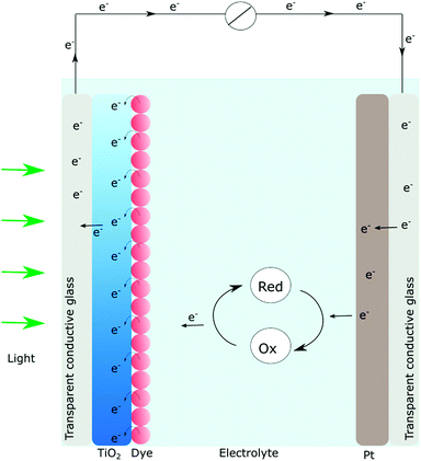
In short, a DSSC (Fig. 2) consists of a dye sensitized photoanode that comprises a thin film of nanocrystalline, mesoporous TiO2 ensuring a large surface area. Since TiO2 absorbs mainly UV-light, visible light absorption is achieved by anchoring of molecular dyes. The photosensitizer should match the solar spectrum and provide enough driving force for the initial charge separation event. Subsequent to absorption, occurring on a femtosecond timescale, the electronically excited dyes can inject electrons into the conduction band of TiO2. Typically charge injection is a very fast process (fs to ps) even though kinetics on the nanosecond timescale has been reported.9,10,30,31Once in the thin film, the electrons are (ideally) transported through the semiconductor particle network and into an external circuit where the electrical current is generated. The now oxidized dye is regenerated by a redox mediator in the electrolyte and the circuit is closed when the electrons in the external circuit reach the counter electrode.9,10 In practice, the overall efficiencies are often not approaching their theoretical maximum conversion efficiencies, due to parasitic reactions. The causes may be low injection yields from the photoexcited dye or, the so-called charge recombination (oftentimes referred to as back electron transfer) where electrons in the conduction band recombine with the oxidized dye. Poor injection yields typically result in low photocurrents while charge recombination may cause low open circuit voltages. Much research effort has gone into both these matters. Nowadays the primary charge separation process is well understood both in purely molecular assemblies and in the dye-sensitized systems.
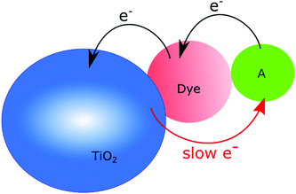
Charge recombination is a somewhat different story, since many believe that if only the electron transport is efficient enough in the semiconductor, it will not affect the efficiency of a solar cell, although it is well established that efficient charge recombination can hamper the open circuit voltage. In nanostructured photoanodes, charge recombination often occurs on the microsecond to millisecond time scales, which provides enough time for the desired chemistry to occur. The fact that the conduction band of nanostructured wide bandgap semiconductors can serve as a charge reservoir, capable of accommodating several electrons per particle over long periods of time, make them a great starting point for solar fuel assemblies.5,14,32–38 If fast charge recombination is avoided, the electrons can instead travel through the conduction band (conduction band mediation) to an anchored acceptor and be used to create the desired highly reduced, catalytically active states needed.34–36 The conduction band mediated approach is illustrated in Fig. 3.
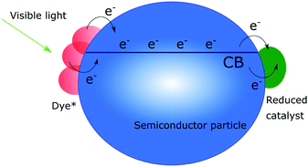 | ||
| Fig. 3 Schematic illustration of the conduction band mediated electron transfer approach in a dye-sensitized semiconductor–catalyst assembly. | ||
As mentioned above, nanostructured photoanodes can routinely sustain charge separated states over millisecond timescales. While charge separation lifetimes or radical pair lifetimes in the same time range have been reported by Wenger, Imahori and others,6,17,29 it is still easier to achieve long lived charge separation in a dye sensitized TiO2 electrode.
The quest for multiple electron transfer
Apart from efficient light capture and long lived charge separation, multiple electron transfer is essential in order to produce solar fuels, as noted earlier.1,11,13,14 In natural photosynthesis, absorption of sunlight leads to four sequential electron transfer steps which yield a charge separated state with close to 100% efficiency.11,39 This process focuses four electrons and four holes on the reaction centers where subsequent multi-electron reactions take place, and result in oxidation of water and reduction of carbon dioxide respectively. Transfer of at least two electrons is necessary also in synthetic systems in order to generate desirable products, and if coupled to water oxidation four electrons are needed. Even though a lot of effort has been put in the design and synthesis of molecular systems for artificial photosynthesis, and many fundamental insights have been achieved, the molecular systems commonly cannot compete with the semiconductor assemblies regarding long-term stability.Since semiconductors as opposed to molecules have the desired ability to store many electrons in the conduction band, they are good candidates for performing the aforementioned multi-electron transfer steps.32,40 How many electrons that can be stored is typically dependent on the size. TiO2 nanoparticles have been reported to store a large number of electrons, with up to 40 electrons for 5 nm-particles being observed, although a more common number used in the literature is around 10 electrons per particle.32,41 ZnO nanocrystals can store 8 electrons per nanocrystal if the radius is 1.7 nm while as many as 120 can be stored when r = 3.5 nm.40 Furthermore, Mayer and coworkers have suggested that proton coupled reactions may provide the opportunity for even higher number of stored electrons.40,41 Semiconductors can not only act as charge reservoirs, but also transfer the accumulated electrons to acceptor molecules anchored to the surface. One of the first reports to recognize this was written by Staniszewski et al. where they showed that electrons from the conduction band of mesoporous TiO2 could be used to reduce molecules that were anchored to the surface, following photoexcitation of the TiO2.35 If the anchored molecules have suitable reduction potentials below the conduction band, this happens quickly, and the molecules can stay reduced for a long time. Since then reports on two electron transfer from the conduction band to anchored molecules have been presented.34
Dye-sensitized semiconductors enable the use of visible light for accumulating electrons in the conduction band. Since several dye molecules can be attached to each nanoparticle and inject electrons with a quantum yield close to 100%,10,42 many electrons can be accumulated and possibly be used for further transfer to anchored catalysts. Dye-sensitized photocatalysis, where dye-sensitized semiconductors are modified with molecular catalysts, takes advantage of this. These assemblies are inspired by the DSSC but instead of being collected as a current, conduction band mediated electron transfer moves electrons from the excited dye to a catalyst active for fuel production, see Fig. 3. The oxidized dye should then ideally be regenerated by a catalyst active for water oxidation.4,5,37,43
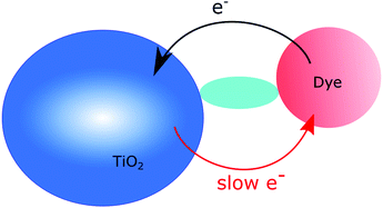
A relatively new device that has been gaining much attention recently, which is also based on the DSSCs, is the dye sensitized photoelectrosynthesis cell (DSPEC), Fig. 4.44,45 In DSPECs, photosensitizer–catalyst assemblies and semiconductors are combined and the solar fuel reactions are separated into two different half-reactions. The oxidation of water should occur at the photoanode and the reductive chemistry should take place at the photocathode.45 While extremely appealing, it is important to note that much more research is needed on the DSPECs and the conduction band mediated approach is a key to the detailed understanding of the processes that govern the overall efficiency. One of the first challenges that need to be addressed to move forward in this field is how to achieve long-lived charge separation.
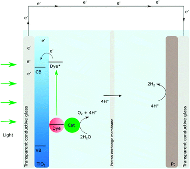 | ||
| Fig. 4 Schematic illustration of the dye sensitized photoelectrochemical synthesis cell, the DSPEC, adapted from ref. 44 and 45. | ||
Realizing long-lived charge separation in nanostructured dye-sensitized photoelectrodes
In general, a few different approaches to long-lived charge separation in dye sensitized photoanodes can be recognized. In short, they can be divided into three main categories, which we will refer to as the molecular, the environmental, and the materials approach, respectively. In the molecular approach, the dye that sensitizes the electrode is manipulated to enhance a desired property or to suppress an unwanted reaction. The environmental strategy focuses instead on the environment that the sensitized photoelectrode experiences, taking into account matters such as electrostatics, pH, polarity and viscosity. Finally, in the materials approach, the engineering of the materials and how it affects the charge transfer properties is the key point of research. Here we will discuss all of these approaches with a focus on the molecular and materials approaches.The molecular approach
Essentially, two main paths can be distinguished within this approach: (1) the intra-ligand charge transfer strategy and (2) the spacer strategy.One notable advantage with this strategy is the possibility to extend the charge separation and at the same time add other functions, e.g. incorporation of a motif that also allows for higher molar absorption coefficients. One strategy to accomplish this is to combine Ru-polypyridyl-type dyes (typical anchoring groups for Ru-polypyridyl dyes are shown in Fig. 6) with substituted 9′-(1,3-dithiole-2-ylidene)-4′,5′-diazafluorene motifs, Fig. 6.46,47 This gives rise to absorption efficiencies in the visible range that are more than two times higher than that achieved with the non-substituted Ru-polypyridine type complexes. Importantly, attaching these molecules to nanocrystalline TiO2 and exciting with pulsed laser light in the visible region yields a very long-lived charge separated state. A positive absorption feature centered around 520–540 nm – which is not observed for Ru-polypyridyl type dyes – formed within the time resolution of the nanosecond transient absorption experiment.
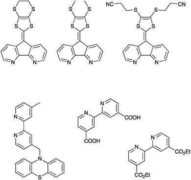 | ||
| Fig. 6 Upper: The substituted 9′-(1,3-dithiole-2-ylidene)-4′,5′-diazafluorene ligands discussed above, reported in ref. 46 and 47. Lower left: An example of the less strongly coupled ligands designed to promote hole transfer, reported in ref. 48. Lower right: Common binding motifs for Ru(II)-based sensitizers for TiO2, a 2,2′-bipyridine ligand substituted with either carboxylic acids or diethylester motifs in the 4 and 4′ positions. | ||
The signal corresponding to the charge separated states hardly loses amplitude over the first 20–40 microseconds after excitation,46 which is also uncommon for this type of sensitizers. This rather unusual observation was attributed to a hole transfer from the ruthenium core to the 9′-(1,3-dithiole-2-ylidene)-4′,5′-diazafluorene ligands. Comparisons with the commonly used electron donor tetrathiafulvalene and derivatives thereof confirmed that the oxidized molecule should have a positive spectral feature in that region. Bimolecular quenching experiments with a Ru-complex with a suitable potential confirmed that oxidation of 9′-(1,3-dithiole-2-ylidene)-4′,5′-diazafluorene ligands gives rise to a similar spectral signal, further supporting this conclusion.46
This strategy has also been used in dyes where the electron donor was more weakly coupled to the core chromophore motif. This includes phenothiazine donors and triarylamine donors. Often lower photon-to-current conversion efficiencies were observed in these cases, although more recent results have suggested that this approach combined with organic dyes can be successful also in generating overall increased efficiencies.48–50 As shown by Odobel, Hammarström and coworkers, this approach can also be used for accumulation of holes at the donor site of the photosensitizer, as shown for a oligotriarylamine donor bound to a ruthenium sensitizer that was also attached to a TiO2 thin film.51
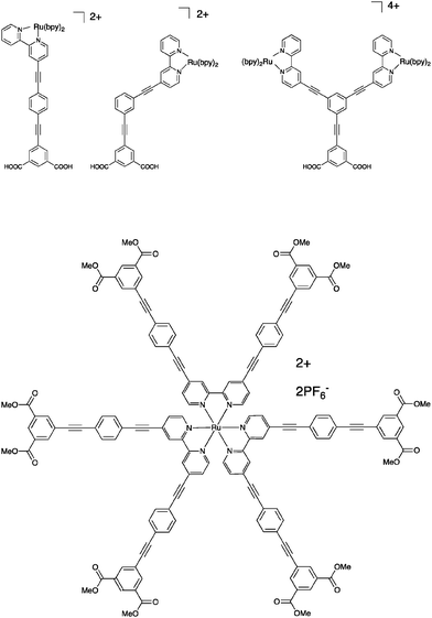
This strategy has been explored in several different ways. In the first example we will discuss here, a Ru(bpy)3-type (bpy is 2,2′-bipyridine) chromophore was utilized and anchored to the TiO2 surface through isophthalic acid and bridged via an oligophenylene–ethynylene spacer, Fig. 8.52 The chromophore was attached either in the para-position or in the meta-position relative to the bridge, and the possibility of attaching two chromophores using both meta-positions was also explored. Connection in the meta-position breaks the conjugation and this has impact on the absorption properties. The injection yields were estimated to be around 15%, and were insensitive to the connection point of the chromophore, i.e. the broken conjugation is not responsible for the low injection efficiency. The effect of the spacer on charge recombination rates was at best unremarkable, but due to the low injection efficiencies, it is hard to know the effect of the spacer.
 | ||
| Fig. 8 Upper: The spacer molecules where the position of the chromophore is varied relative to the anchoring bridge, reported in ref. 52. Lower: One of the star-shaped molecules reported in ref. 31 and 53. | ||
It can be argued however that connection of one single bridge motif may not in fact separate the chromophore core from the surface to the extent needed, especially not when using an octahedrally shaped chromophore like Ru(bpy)32+. Therefore, a series of star-shaped molecules were studied, where in total 6 spacers were connected to the chromophore, one in each 4 and 4′-position of all the three bipyridine ligands, Fig. 8.31,53
Each bridge was terminated with isophthalic esters to provide anchoring points. The charge injection was inefficient and very slow, to the point that some parts of it could be time-resolved on a nanosecond time scale. The subsequent charge recombination is also very slow, and not complete within the first 90 milliseconds after excitation. In other words, here the spacers work well for slowing down charge recombination, but the approach may be less useful when a high concentration of electrons in the conduction band is essential. Later, this work was expanded upon, but the main conclusions remained the same – the electron injection is slow and inefficient, but the charge separation is sustained over a time scale of ca. 100 milliseconds.31,53 For Ru(bpy)32+-type dyes, spacer elongation decelerates the undesired charge recombination reaction, but at the same time it also decelerates the desired photoinduced charge separation events. This is not unexpected per se, but it should be pointed out that it is possible to have different distance dependencies of forward and back electron transfer rates as shown by Pettersson and Wiberg et al.54,55
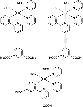
The spacer approach was also applied to a N3-type chromophore56 – a Ru ion coordinates two NCS ligands, one bpy and one bpy substituted with a phenylenethynylene spacer, terminated with either carboxylic acids or methoxy groups for anchoring purposes, Fig. 9. In this case electron injection was faster than the time resolution of the nanosecond instrument used to monitor it, and as anticipated the injection yields were high. Interestingly, some population of the charge separation was sustained at least up to timescales of around 5 milliseconds for both anchoring groups, much longer than for the reference compound without a spacer, suggesting that order-of-magnitude differences in forward and backward electron transfer rates are possible in dye-sensitized photoelectrodes.
 | ||
| Fig. 9 The molecules used in the study that combined dyes with high injection yields and short bridges, reported in ref. 56. | ||
The longer-lasting charge separation is also evident in the photoelectrochemical measurements where a higher open circuit voltage is observed for the spacer molecules, consistent with what is predicted by the diode equation.56 Thus, it can be concluded that the spacer approach can be useful but depending on the purpose – fast injection or long-lived charge separation – the chromophore must be chosen with care. Also it cannot be excluded that the anchoring group itself may have an impact, and the results in the literature discussed here suggest that the isophthalic acid may not be the best choice.
The environmental approach
We have also investigated the effect of the environment on charge recombination in two different studies. The first study used all ionic liquid-electrolytes and compared their impact on the charge recombination in three different dye-TiO2 thin film assemblies.57 In these results a clear difference was manifest between the different dyes – the ones employed were one organic, uncharged dye, one charged Ru-based dye and one uncharged Ru-based dye (the commonly used N3-dye). Interestingly, a comparison between different electrolytes revealed non-significant differences in charge recombination for N3, while there was a clear extension of the charge separated lifetime in the ionic liquid electrolytes for the two other dyes, suggesting that for multi-electron transfer purposes in a conduction band mediated approach, not only the injection yield is important to consider, but also the dye structure itself.In the second study, we experimented with cationic additives to quasi-solid state electrolytes and the organic D35 as the dye.58 Very small effects could be seen when comparing Rb and Cs ions as additives, where the charge recombination was somewhat longer in the Rb-ion case. However, as evident from the photoelectrochemical measurements, it is clear that either the injection yields are very poor or that a very large part of the injected electrons are recombining on ultrafast time scales. Thus, no strong conclusions can be drawn from these results in terms of how to design a well-functioning conduction band mediated hybrid system. It is however worth noting that ions other than the known redox mediators like I− may be less innocent than typically anticipated.
Materials approaches to long-lived charge separation in hybrid systems
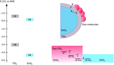
When using dye-sensitized semiconductors for producing solar fuels, apart from the clever choice or design of the photosensitizer and environment around it, efficient design of the materials in the photoanode can yield longer lived charge separated states necessary for solar fuel reactions.Several approaches of constructing mixed semiconductor photoanodes to prolong the charge separated lifetime have been reported; Fig. 10 illustrates examples of this using a combination of TiO2 and SnO2. The main advantage of combining different semiconductors is the possibility to make use of the different energy levels of the conduction band in the individual semiconductors. If the films are constructed so that electrons can flow from a semiconductor with a higher CB potential to one with a lower CB potential, an electron transfer cascade can be created which is more efficient than electron transfer in only one step.59 Using this approach however requires a careful design of the photoanode so that the electrons will flow in the desired energy direction without encountering unnecessary energy barriers. One straightforward way of combining different semiconductors is by creating mixtures of different nanoparticles; the first example of this was the preparation of mixed colloids which improved the charge separation.59–63 Following this, mixed films of different semiconductor nanoparticles have been prepared for photocatalytic applications. Both devices for photocatalytic degradation of dyes63 and dye-sensitized photovoltaic cells62 based on mixed films have yielded suppressed charge recombination from inter-particle electron transfer.
Several groups have taken advantage of the energy level alignment between different semiconductors by constructing core–shell structures that allow for directed electron transfer between them, Fig. 10.64–70 A common combination of this is TiO2 and SnO2; since SnO2 has a CB potential ∼0.4 V more positive than TiO266 electrons are expected to flow from TiO2 to SnO2. The relative bandgap positions of TiO2 and SnO2 are shown in Fig. 10.
In this approach, the main part of the electrode consists of a layer of SnO2 making up the core which then is covered by a thin layer of TiO2, i.e. the shell. By this design, electrons can flow in the desired direction without facing energy barriers, while the back electron transfer is slowed down by the barrier for the electron transfer from SnO2 to TiO2. Core–shell structures of different semiconductors have been successfully implemented in DSSCs to suppress the interfacial charge recombination and improve the performance of the solar cells.64,67
Suppressing interfacial charge recombination becomes increasingly important in the DSPEC compared to in a DSSC, since there the lifetime of the charge separated state needs to match the rate of the water oxidation reaction and the hole transport. Interfacial charge recombination to the oxidized dye therefore becomes a substantial loss pathway for these devices.69 Recently, several groups have constructed core–shell structures of SnO2/TiO2 by using atomic layer deposition (ALD) to deposit TiO2 on SnO2 nanoparticles.68,70 These core–shell structures have been successfully used as photoanodes in DSPECs with higher efficiencies and a ∼1000 time increase in the half-life of the charge separated state. The use of ALD also provides opportunity to control the thickness of the shell to optimize the performance. Studies where the thickness of the TiO2 shell has been varied suggest that the optimal shell thickness is a few nanometers,70,71 below which the back-electron transfer occurs via a tunneling mechanism from the SnO2 core, and if thicker layers are used, the back-electron transfer originates from electrons in the TiO2 shell.71
Another avenue explored can be highlighted with a recent example from our laboratory, where we combined TiO2 with SnO2 in a hybrid system to create patterned dye-sensitized TiO2/SnO2 films, Fig. 10.38 These films are easily prepared via screen-printing and do not require expensive methods like ALD. Here, mesoporous, micrometer thin layers of TiO2 were strategically assembled on top of SnO2-films. The TiO2 part can then be selectively dye-sensitized leaving dye-free SnO2 areas where electrons can be accumulated. Since the TiO2 layer is a few micrometers thick, the high injection yield in TiO2 can be maintained. The ∼100 times higher electron mobility in SnO2 compared to TiO2 can furthermore facilitate accumulation of electrons in the SnO2 areas of the film.64 Patterned films with selective dye-sensitization of the TiO2-areas yield a ∼50 time increase in charge separated lifetime at sufficiently high excitation powers compared to dye-sensitized TiO2 films and patterned TiO2/SnO2 which are homogeneously dye-sensitized. These patterned films also allow for spatial separation of immobilized dyes and catalysts, making it possible for direct use of the conduction band mediated approach for producing solar fuels.38
Electron transfer to model catalysts through conduction band mediated pathways
As can be understood from the results discussed above, a lot of progress has been achieved in understanding how to extend the charge separated lifetime. In order to have an efficient system for producing solar fuels, it is also important to optimize the cathode side of the DSPEC and the electron transfer to the reducing catalyst in dye sensitized hybrid devices. Nickel oxide (NiO) is the most commonly studied p-type semiconductor as the photocathode in tandem DSPECs, and reduction of H2O has been reported in a tandem cell using NiO as the photocathode.72 Relatively long lived reduced catalysts following hole injection from adsorbed dyes and surface electron transfer to a co-adsorbed catalyst have furthermore been reported.73One advantage of instead directly using dye-sensitized semiconductors sensitized with molecular catalysts for producing solar fuels would be the abovementioned ability of the conduction band to store and transfer multiple electrons. The fact that electrons in the CB can be transferred to attached molecules points to the potential of using the CB as a mediator for the electron transfer. Two-electron transfer to metalloporphyrins anchored to mesoporous TiO2 thin films have been achieved by transfer of electrons stored in the conduction band. This process has yet to be controlled by visible light. The different redox states of these complexes have distinct spectroscopic features, making it possible to study the respective reduction reactions. By white-light excitation of the TiO2, two clear subsequent reductions of the attached porphyrins from the original CoIII state to CoI together with an increase of electrons in the CB are observed spectroscopically.34
Hybrid systems consisting of dye molecules and molecular catalysts attached to mesoporous TiO2 have been used for the reduction of protons to hydrogen5,37 as well as the reduction of CO2 to CO.3 The efficiencies of these systems remain low, and one reason for this is the relatively slow second reduction of the catalyst. In a study by Lakadamyali et al. it was found that high loading of catalyst, low excitation powers together with a high driving force for electron transfer are necessary to increase the efficiency of the first electron transfer to a Co-porphyrin catalyst at the surface.5 By studies of the electron lifetime in the conduction band they concluded that the second reduction of the catalyst is several orders of magnitude slower than the first reduction. This would then imply that it is necessary for all catalyst molecules to undergo the first reduction before any two electron reductions can occur. Furthermore, the second reduction steps need a sacrificial electron donor to occur.74 The sacrificial electron donor should ideally be replaced with oxidation of water for a fully functional system. This example yet again highlights the importance of long-lived charge separation at the dye–semiconductor interface since the catalysts capable of water oxidation must be given enough time to perform the desired chemistry.
The patterned TiO2/SnO2 approach comes with the advantage that the conduction band can be used as a mediator for the electron transfer while at the same time the catalyst can be anchored to the SnO2 parts and thus spatially separated from the dye. This could facilitate the electron transfer to the catalyst while slowing down the interfacial recombination to the dye. The potential of using the patterned approach has been confirmed by the conduction band mediated reduction of a model catalyst which was attached to the dye-free SnO2 areas only. By selective excitation of the dye-sensitized TiO2 areas, reduction of the catalyst on the SnO2-areas was clearly observed spectroscopically.38 This together with the fact that the lifetime of the charge separated state gets significantly increased in these films points to it being a promising design for these systems.
Outlook and concluding remarks
Solar fuel research is currently attracting a lot of attention from researchers as well as policymakers, and rightly so because of its inherent potential to transform our current energy system into sustainable alternatives. As argued above, realizing efficient and sustainable solar energy conversion still requires much research work on the fundamental questions. This Feature Article is focused on one of these fundamental aspects – how to produce stable, long lived charge separated states in high yields in dye-sensitized nanostructured semiconductor materials. As discussed, several approaches can be distinguished from the literature, some with very promising properties suggesting that they may be able to facilitate the next step – multiple charge transfer reactions.Observations of photoinduced multi-electron transfer reactions are still scarce, and the low efficiencies and the complex reactions reported are strong indications that there is still a need to design model systems where the factors governing multiple charge transfer events can be systematically studied. This applies to DSPEC systems, the less elaborate approach described here and shown in Fig. 3 as well as the molecular assemblies where radical pairs have been sustained over long time scales. In particular, we need to learn how to control and minimize parasitic losses, especially in the secondary and later charge transfer steps. As accumulation of charges in working solar fuel producing devices should occur from continuous light illumination, losses by excitation of created photoproducts need to be explored and minimized. To understand how and why such losses occur, pump–pump–probe experiments are necessary and will yield useful information about both charge separation kinetics and yields as well as provide information on side reactions from the secondary excitation of the initial photoproduct. This may be especially useful given the recent results reported by Weinstein and others implying that reaction pathways could be turned on or off depending on the pump light frequency.75 It is important to note that further development of both pump–pump–probe techniques and continuous illumination experiments will be necessary for the development of this field.
In our laboratory we have recently gathered experimental proof for one electron transfer reaction from an excited dye, through two semiconductors and eventually to a catalyst molecule also attached to the semiconductor thin film, through a conduction band mediated process.38 Additionally, very promising preliminary results, currently being confirmed and prepared for publication, suggest that we can achieve a double electron transfer reduction of a model catalyst, in a similar conduction band mediated manner, but using one semiconductor only. While these results are promising, it is important to keep in mind that the minimum number of electron transfer reactions needed to realize solar fuels are four. Therefore, it will most likely be a worthwhile route to investigate how redox equivalent transfer, possibly PCET, rather than electron transfer can be beneficial in dye-sensitized nanostructured semiconductor assemblies. For example, this may pave the way for use of new molecular catalysts. To date, very few papers on this topic exist, but it is an avenue that should be explored, as clearly indicated by the report from e.g. Mayer.41
Achieving the goal of solar fuel generation requires that we can master all aspects of multiple electron transfer events. Currently, light absorption and primary charge separation are well understood in molecular assemblies as well as in dye-sensitized nanostructured semiconductor assemblies. This Feature Article highlights strategies to overcome the detrimental charge recombination in dye/semiconductor systems and highlights that conduction band mediated electron transfer can indeed occur. In addition, it will be necessary to gain detailed understanding of how secondary charge transfer kinetics can be tuned and how the catalytically active states can be stabilized.
Conflicts of interest
There are no conflicts of interest to declare.Acknowledgements
M. A. thanks the Swedish Research Council (Vetenskapsrådet) for financial support.Notes and references
- L. Hammarstråm, Acc. Chem. Res., 2015, 48, 840–850 CrossRef PubMed.
- L. C. Sun, L. Hammarstråm, B. Akermark and S. Styring, Chem. Soc. Rev., 2001, 30, 36–49 RSC.
- J. S. Lee, D. I. Won, W. J. Jung, H. J. Son, C. Pac and S. O. Kang, Angew. Chem., Int. Ed., 2017, 56, 976–980 CrossRef CAS PubMed.
- J. Willkomm, K. L. Orchard, A. Reynal, E. Pastor, J. R. Durrant and E. Reisner, Chem. Soc. Rev., 2016, 45, 9–23 RSC.
- F. Lakadamyali, A. Reynal, M. Kato, J. R. Durrant and E. Reisner, Chem. – Eur. J., 2012, 18, 15464–15475 CrossRef CAS PubMed.
- S. M. Marinho, M. H. Ha-Thi, V. T. Pham, A. Quaranta, T. Pino, C. Lefumeux, T. Chamaille, W. Leibl and A. Aukauloo, Angew. Chem., Int. Ed., 2017, 56, 15936–15940 CrossRef PubMed.
- H. Y. Cheong, S. Y. Kim, Y. J. Cho, D. W. Cho, C. H. Kim, H. J. Son, C. Pac and S. O. Kang, Inorg. Chem., 2017, 56, 12042–12053 CrossRef CAS PubMed.
- J. Warnan, J. Willkomm, J. N. Ng, R. Godin, S. Prantl, J. R. Durrant and E. Reisner, Chem. Sci., 2017, 8, 3070–3079 RSC.
- A. Hagfeldt and M. Gratzel, Chem. Rev., 1995, 95, 49–68 CrossRef CAS.
- A. Hagfeldt, G. Boschloo, L. C. Sun, L. Kloo and H. Pettersson, Chem. Rev., 2010, 110, 6595–6663 CrossRef CAS PubMed.
- Y. Tachibana, L. Vayssieres and J. R. Durrant, Nat. Photonics, 2012, 6, 511–518 CrossRef CAS.
- N. Sutin, C. Creutz and E. Fujita, Comments Inorg. Chem., 1997, 19, 67–92 CrossRef CAS.
- E. E. Benson, C. P. Kubiak, A. J. Sathrum and J. M. Smieja, Chem. Soc. Rev., 2009, 38, 89–99 RSC.
- J. D. Megiatto, A. Antoniuk-Pablant, B. D. Sherman, G. Kodis, M. Gervaldo, T. A. Moore, A. L. Moore and D. Gust, Proc. Natl. Acad. Sci. U. S. A., 2012, 109, 15578–15583 CrossRef CAS PubMed.
- A. J. Morris, G. J. Meyer and E. Fujita, Acc. Chem. Res., 2009, 42, 1983–1994 CrossRef CAS PubMed.
- M. Kuss-Petermann and O. Wenger, Helv. Chim. Acta, 2017, 100 Search PubMed.
- M. Yamamoto, J. Fohlinger, J. Petersson, L. Hammarstråm and H. Imahori, Angew. Chem., Int. Ed., 2017, 56, 3329–3333 CrossRef CAS PubMed.
- M. Kuss-Petermann, M. Orazietti, M. Neuburger, P. Hamm and O. Wenger, J. Am. Chem. Soc., 2017, 139, 5225–5232 CrossRef CAS PubMed.
- J. Chen, M. Kuss-Petermann and O. Wenger, Chem. – Eur. J., 2014, 20, 4098–4104 CrossRef CAS PubMed.
- J. Chen, M. Kuss-Petermann and O. Wenger, J. Phys. Chem. B, 2015, 119, 2263–2273 CrossRef CAS PubMed.
- R. Hones, M. Kuss-Petermann and O. Wenger, Photochem. Photobiol. Sci., 2013, 12, 254–261 Search PubMed.
- M. Kuss-Petermann and O. Wenger, J. Phys. Chem. Lett., 2013, 4, 2535–2539 CrossRef CAS.
- M. Kuss-Petermann and O. Wenger, J. Phys. Chem. A, 2013, 117, 5726–5733 CrossRef CAS PubMed.
- L. Hammarstråm and S. Styring, Energy Environ. Sci., 2011, 4, 2379–2388 Search PubMed.
- J. M. Mayer, Annu. Rev. Phys. Chem., 2004, 55, 363–390 CrossRef CAS PubMed.
- J. M. Mayer, I. J. Rhile, F. B. Larsen, E. A. Mader, T. F. Markle and A. G. Dipasquale, Photosynth. Res., 2006, 87, 21–24 CrossRef CAS.
- M. Sjodin, S. Styring, H. Wolpher, Y. H. Xu, L. C. Sun and L. Hammarstråm, J. Am. Chem. Soc., 2005, 127, 3855–3863 CrossRef PubMed.
- R. I. Cukier and D. G. Nocera, Annu. Rev. Phys. Chem., 1998, 49, 337–369 CrossRef CAS PubMed.
- M. Orazietti, M. Kuss-Petermann, P. Hamm and O. Wenger, Angew. Chem., Int. Ed., 2016, 55, 9407–9410 CrossRef CAS PubMed.
- J. Kallioinen, G. Benko, P. Myllyperkio, L. Khriachtchev, B. Skarman, R. Wallenberg, M. Tuomikoski, J. Korppi-Tommola, V. Sundstrom and A. P. Yartsev, J. Phys. Chem. B, 2004, 108, 6365–6373 CrossRef CAS PubMed.
- P. G. Johansson, Y. Y. Zhang, M. Abrahamsson, G. J. Meyer and E. Galoppini, Chem. Commun., 2011, 47, 6410–6412 RSC.
- H. H. Mohamed, C. B. Mendive, R. Dillert and D. W. Bahnemann, J. Phys. Chem. A, 2011, 115, 2139–2147 CrossRef CAS PubMed.
- H. H. Mohamed, R. Dillert and D. W. Bahnemann, J. Photochem. Photobiol., A, 2011, 217, 271–274 CrossRef CAS.
- S. Ardo, D. Achey, A. J. Morris, M. Abrahamsson and G. J. Meyer, J. Am. Chem. Soc., 2011, 133, 16572–16580 CrossRef CAS PubMed.
- A. Staniszewski, A. J. Morris, T. Ito and G. J. Meyer, J. Phys. Chem. B, 2007, 111, 6822–6828 CrossRef CAS PubMed.
- J. R. Stromberg, J. D. Wnuk, R. A. F. Pinlac and G. J. Meyer, Nano Lett., 2006, 6, 1284–1286 CrossRef CAS PubMed.
- F. Lakadamyali and E. Reisner, Chem. Commun., 2011, 47, 1695–1697 RSC.
- V. Becerril, E. Sundin, M. Mapar and M. Abrahamsson, Phys. Chem. Chem. Phys., 2017, 19, 22684–22690 RSC.
- D. Gust, T. A. Moore and A. L. Moore, Acc. Chem. Res., 1993, 26, 198–205 CrossRef CAS.
- C. N. Valdez, A. M. Schimpf, D. R. Gamelin and J. M. Mayer, J. Am. Chem. Soc., 2016, 138, 1377–1385 CrossRef CAS PubMed.
- J. N. Schrauben, R. Hayoun, C. N. Valdez, M. Braten, L. Fridley and J. M. Mayer, Science, 2012, 336, 1298–1301 CrossRef CAS PubMed.
- S. E. Koops, B. C. O’Regan, P. R. F. Barnes and J. R. Durrant, J. Am. Chem. Soc., 2009, 131, 4808–4818 CrossRef CAS PubMed.
- E. Reisner, D. J. Powell, C. Cavazza, J. C. Fontecilla-Camps and F. A. Armstrong, J. Am. Chem. Soc., 2009, 131, 18457–18466 CrossRef CAS PubMed.
- M. K. Brennaman, R. J. Dillon, L. Alibabaei, M. K. Gish, C. J. Dares, D. L. Ashford, R. L. House, G. J. Meyer, J. M. Papanikolas and T. J. Meyer, J. Am. Chem. Soc., 2016, 138, 13085–13102 CrossRef CAS PubMed.
- L. Alibabaei, B. D. Sherman, M. R. Norris, M. K. Brennaman and T. J. Meyer, Proc. Natl. Acad. Sci. U. S. A., 2015, 112, 5899–5902 CrossRef CAS PubMed.
- M. Abrahamsson, J. H. J. Hedberg, H.-C. Becker, A. Staniszewski, W. H. Pearson, W. B. Heuer and G. J. Meyer, ChemPhysChem, 2014, 15, 1154–1163 CrossRef CAS PubMed.
- A. Staniszewski, W. B. Heuer and G. J. Meyer, Inorg. Chem., 2008, 47, 7062–7064 CrossRef CAS PubMed.
- R. Argazzi, C. A. Bignozzi, T. A. Heimer, F. N. Castellano and G. J. Meyer, J. Am. Chem. Soc., 1995, 117, 11815–11816 CrossRef CAS.
- R. Argazzi, C. A. Bignozzi, T. A. Heimer, F. N. Castellano and G. J. Meyer, J. Phys. Chem. B, 1997, 101, 2591–2597 CrossRef CAS.
- P. Bonhote, J. E. Moser, R. Humphry-Baker, N. Vlachopoulos, S. M. Zakeeruddin, L. Walder and M. Gratzel, J. Am. Chem. Soc., 1999, 121, 1324–1336 CrossRef CAS.
- S. Karlsson, J. Boixel, Y. Pellegrin, E. Blart, H. C. Becker, F. Odobel and L. Hammarstråm, J. Am. Chem. Soc., 2010, 132, 17977–17979 CrossRef CAS PubMed.
- M. Abrahamsson, O. Taratula, P. Persson, E. Galoppini and G. Meyer, J. Photochem. Photobiol., A, 2009, 206, 155–163 CrossRef CAS.
- P. G. Johansson, Y. Y. Zhang, G. J. Meyer and E. Galoppini, Inorg. Chem., 2013, 52, 7947–7957 CrossRef CAS PubMed.
- K. Pettersson, J. Wiberg, T. Ljungdahl, J. Martensson and B. Albinsson, J. Phys. Chem. A, 2006, 110, 319–326 CrossRef CAS PubMed.
- J. Wiberg, L. J. Guo, K. Pettersson, D. Nilsson, T. Ljungdahl, J. Martensson and B. Albinsson, J. Am. Chem. Soc., 2007, 129, 155–163 CrossRef CAS PubMed.
- M. Abrahamsson, P. Johansson, S. Ardo, A. Kopecky, E. Galoppini and G. Meyer, J. Phys. Chem. Lett., 2010, 1, 1725–1728 CrossRef CAS.
- V. Becerril, D. Franchi and M. Abrahamsson, J. Phys. Chem. C, 2016, 120, 20016–20023 Search PubMed.
- O. Bettucci, V. Becerril, T. Bandara, M. Furlani, M. Abrahamsson, B. Mellander and L. Zani, Phys. Chem. Chem. Phys., 2018, 20, 1276–1285 RSC.
- H. Hayashi, I. V. Lightcap, M. Tsujimoto, M. Takano, T. Umeyama, P. V. Kamat and H. Imahori, J. Am. Chem. Soc., 2011, 133, 7684–7687 CrossRef CAS PubMed.
- N. Serpone, E. Borgarello and M. Gratzel, J. Chem. Soc., Chem. Commun., 1984, 342–344 RSC.
- N. Serpone, P. Maruthamuthu, P. Pichat, E. Pelizzetti and H. Hidaka, J. Photochem. Photobiol., A, 1995, 85, 247–255 CrossRef CAS.
- K. Tennakone, V. P. S. Perera, I. R. M. Kottegoda and G. Kumara, J. Phys. D: Appl. Phys., 1999, 32, 374–379 CrossRef CAS.
- K. Vinodgopal, I. Bedja and P. V. Kamat, Chem. Mater., 1996, 8, 2180–2187 CrossRef CAS.
- S. Chappel, S. G. Chen and A. Zaban, Langmuir, 2002, 18, 3336–3342 CrossRef CAS.
- H. J. Snaith and C. Ducati, Nano Lett., 2010, 10, 1259–1265 CrossRef CAS PubMed.
- P. Tiwana, P. Docampo, M. B. Johnston, H. J. Snaith and L. M. Herz, ACS Nano, 2011, 5, 5158–5166 CrossRef CAS PubMed.
- B. A. Gregg, F. Pichot, S. Ferrere and C. L. Fields, J. Phys. Chem. B, 2001, 105, 1422–1429 CrossRef CAS.
- N. S. McCool, J. R. Swierk, C. T. Nemes, C. A. Schmuttenmaer and T. E. Mallouk, J. Phys. Chem. Lett., 2016, 7, 2930–2934 CrossRef CAS PubMed.
- J. R. Swierk, N. S. McCool and T. E. Mallouk, J. Phys. Chem. C, 2015, 119, 13858–13867 CAS.
- M. K. Gish, A. M. Lapides, M. K. Brennaman, J. L. Templeton, T. J. Meyer and J. M. Papanikolas, J. Phys. Chem. Lett., 2016, 7, 5297–5301 CrossRef CAS PubMed.
- R. R. Knauf, B. Kalanyan, G. N. Parsons and J. L. Dempsey, J. Phys. Chem. C, 2015, 119, 28353–28360 CAS.
- Z. Q. Ji, M. F. He, Z. J. Huang, U. Ozkan and Y. Y. Wu, J. Am. Chem. Soc., 2013, 135, 11696–11699 CrossRef CAS PubMed.
- L. J. Antila, P. Ghamgosar, S. Maji, H. N. Tian, S. Ott and L. Hammarstråm, ACS Energy Lett., 2016, 1, 1106–1111 CrossRef CAS.
- A. Reynal, F. Lakadamyali, M. A. Gross, E. Reisner and J. R. Durrant, Energy Environ. Sci., 2013, 6, 3291–3300 CAS.
- M. Delor, P. A. Scattergood, I. V. Sazanovich, A. W. Parker, G. M. Greetham, A. Meijer, M. Towrie and J. A. Weinstein, Science, 2014, 346, 1492–1495 CrossRef CAS PubMed.
| This journal is © The Royal Society of Chemistry 2018 |

