 Open Access Article
Creative Commons Attribution 3.0 Unported Licence
A Cu–Zn nanoparticle promoter for selective carbon dioxide reduction and its application in visible-light-active Z-scheme systems using water as an electron donor†
Ge
Yin
 a,
Hiroshi
Sako
a,
Ramesh V.
Gubbala
b,
Shigenori
Ueda
c,
Akira
Yamaguchi
a,
Hiroshi
Sako
a,
Ramesh V.
Gubbala
b,
Shigenori
Ueda
c,
Akira
Yamaguchi
 a,
Hideki
Abe
 *b and
Masahiro
Miyauchi
 *a
*a
aDepartment of Materials Science and Engineering, School of Materials and Chemical Technology, Tokyo Institute of Technology, 2-12-1 Ookayama, Meguro-ku, Tokyo 152-8552, Japan. E-mail: mmiyauchi@ceram.titech.ac.jp
bAdvanced Electronic Materials Center, National Institute of Materials Science, 1-1 Namiki, Tsukuba 305-004, Japan. E-mail: ABE.Hideki@nims.go.jp
cSynchrotron X-ray Station at SPring-8, National Institute for Materials Science, 1-1-1 Kouto, Sayo, Hyogo 679-5148, Japan
First published on 13th February 2018
Abstract
Selective carbon dioxide photoreduction to produce formic acid was achieved under visible light irradiation using water molecules as electron donors, similar to natural plants, based on the construction of a Z-scheme light harvesting system modified with a Cu–Zn alloy nanoparticle co-catalyst. The faradaic efficiency of our Z-scheme system for HCOOH generation was over 50% under visible light irradiation.
Artificial photosynthesis for fuel production from carbon dioxide (CO2) and water (H2O), driven by sunlight under moderate conditions, is a very attractive renewable energy strategy to solve the CO2 emission issue.1 Although numerous studies have reported water splitting to produce hydrogen (H2),2,3 photocatalytically reducing CO2 into C1 molecules is more challenging, because it requires a higher reduction overpotential than proton reduction. Moreover, oxygen production is essential, since abundant water molecules should be used as electron donors for CO2 reduction, similar to natural plants. However, many previous studies used sacrificial agents like triethanolamine (TEOA) or ethylenediaminetetraacetic acid (EDTA) to donate electrons.4,5 To provide the high reduction potential and the strong oxidation power for photocatalytic CO2 reduction through water oxidation, wide-gap semiconductors have been used to initiate CO2 reduction under UV light irradiation, i.e. layered metal oxide perovskites (BaLa4Ti4O15),6 niobate nanosheets (Nb3O8−),7 or SrTiO3.8 However, visible-light-driven CO2 photoreduction is more desirable because about half of solar energy ranges in the visible light range. It is very difficult for a narrow-band-gap light harvester material to provide the high reduction potential needed for CO2 reduction as well as the deep oxidation potential for water oxidation.9,10 To overcome the difficulties of using water as an electron donor and a visible light energy source, the Z-scheme system like the photosynthetic reaction centres in natural plants is useful and has previously been reported in the field of environmental purification11 or water splitting.12 Sekizawa et al. reported a Z-scheme system for photocatalytic CO2 reduction by combining cathodic and anodic light harvesters.13 Kudo et al. reported a metal sulfide/BiVO4 Z-scheme using water as the electron donor,14 and achieved the reduction of CO2 into carbon monoxide (CO) under visible light. However, the produced H2 amount was about 100 times higher than CO. Recently, Ishitani et al. also used a Z-scheme system for visible-light-driven CO2 reduction, owing to the noble metal (Ru and Re) organic complex co-catalyst, and CO was selectively produced.15 Its light-to-energy conversion efficiency, however, was still much smaller than that of natural plants. Besides CO, formic acid (HCOOH) is also very desirable C1 chemical for its general utilization in the fields of energy, chemical industry, and even animal husbandry.16 To drive CO2 reduction selectively into CO or HCOOH and to avoid hydrogen production in aqueous media, the co-catalyst modification onto the light harvester is crucial. However, highly selected HCOOH generation has only been achieved by using expensive noble metal-complexes to date.17 In contrast, in our previous research, copper and zinc based bulk alloys were investigated as electrocatalysts for HCOOH production,18 but they could not be applied in photocatalysis or photo-electrochemical systems because of their bulk form and/or high temperature preparation conditions.
Herein, we developed highly dispersed Cu–Zn alloy nanoparticles (NPs) via a moderate chemical co-reduction method and used them as a HCOOH generation promoter. The nanoparticles provide a high surface area to minimize the co-catalyst loading amount onto light harvesting semiconductors. A highly dispersed Cu–Zn NP ink enabled us to coat them onto various light harvesters. Based on these nanoparticles, we constructed a selective visible-light-driven CO2 photoreduction system using water as an electron donor, consisting of robust and economical inorganic components. As for the visible light harvesting system, a CaFe2O4 (CFO) film was used as the photocathode due to its high conduction band edge, ubiquitous elemental composition,19,20 and high photo-current, which can be greatly improved by increasing its crystallinity.19 On the other hand, an oriented WO3 nanotree film was chosen as the photoanode, because it can be fabricated via facile hydrothermal treatment of a metal tungsten substrate with a large surface area and high crystallinity, and its quantum efficiency for water oxidation is quite high.21 On the basis of each component, we constructed a Z-scheme system and evaluated its photocatalytic CO2 reduction properties in the present study. Further, we conducted operando Fourier Transform Infrared Spectrometer (FT-IR) analysis to discuss the selective HCOOH production pathway on the Cu–Zn NPs' surface under real catalysis conditions.
Although our previous study reported the synthesis of the bulk Cu–Zn electrocatalyst for selective CO2 reduction,18 the present study developed the highly dispersed intermetallic Cu–Zn NPs via a wet chemical process and optimized their chemical composition and structure according to the performance of their electrochemical CO2 reduction (described in the ESI† in detail, Fig. S3 and S4). Among various Cu/Zn ratios in NPs, the Cu5Zn8 phase exhibited the lowest onset potential for electrocatalytic CO2 reduction (Fig. S5, ESI†). The optimal size of the Cu–Zn NPs was in the range of 20–40 nm (Fig. 1a). Hard X-ray photoelectron spectroscopy (HAXPES) analyses (Fig. 1b and c) were also performed, and the peak positions of the Cu 2p and Zn 2p core-levels were significantly shifted as compared to the pure Cu and Zn, indicating the formation of an intermetallic structure in the Cu–Zn alloy. The prepared Cu–Zn NPs were finely dispersed into an ink and could be coated onto various powder or film form electrodes by simple drop-casting or spin coating and a vacuum drying procedure at room temperature.
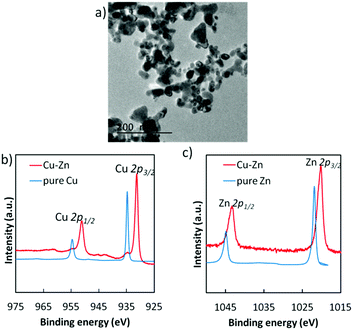 | ||
| Fig. 1 (a) TEM image of Cu–Zn alloy nanoparticles. (b) HAXPES for Cu 2p and (c) Zn 2p core-levels in the prepared Cu–Zn alloy nanoparticles, compared to pure Cu and pure Zn. | ||
Electrocatalytic selectivity for HCOOH generation of the Cu–Zn NP deposited electrode was very high (Fig. S8, ESI†). In addition to the electrocatalysis, we have confirmed that the Cu–Zn NPs act as a co-catalyst with UV-light-active SrTiO3 with more than 50% selectivity for HCOOH generation (Fig. S9 and S10, ESI†).
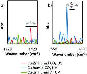
To discuss the high selectivity of Cu–Zn NPs for HCOOH generation, operando FT-IR spectra were analyzed under the almost similar conditions to the real catalytic atmosphere under a humid CO2 atmosphere with UV irradiation (Fig. S11 in the ESI†). As we can see in Fig. 2a, a peak appeared at 1409 cm−1, while there were no peaks in the control groups (more control experiment results are shown in Fig. S12, ESI†). According to the literature, this peak can be assigned to bidentate carbonate22 or bicarbonate,23 whose appearances are commonly considered as the starting species of the HCOOH generation in CO2 reduction.24,25 In contrast, Cu was known for its high selectivity for CH4 or CH3OH. From the spectra of the Cu NP loaded photocatalyst in Fig. 2b, a peak which can be assigned to unidentate carbonate22 or carboxylate23 appeared at 1596 cm−1. The results of operando FT-IR proved that the surface adsorption strength for CO2* active species was adjusted by alloying on the atomic scale as we expected, thus the Cu–Zn NPs exhibited high selectivity for HCOOH generation.
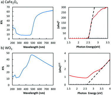
As for the light harvesters to build a visible light sensitive system, a highly (hk0)-oriented CFO electrode was prepared by annealing in air (Fig. S13, ESI†),19,20 whereas the highly oriented WO3 nanotree film used in this study was grown on a tungsten substrate via a hydrothermal process (Fig. S15, ESI†).21Fig. 3 shows the UV-visible absorption spectra of the CFO and WO3 electrodes, showing the bandgaps of CFO and WO3 to be 2.5 and 2.6 eV, respectively, indicating that both are visible-light responsive. The broad absorption of WO3 above 500 nm, shown in Fig. 3b, does not contribute to the photo-current generation because it is attributed to trapped electrons, which have low reduction and oxidation potential and strong localization.26,27
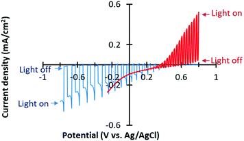
We deposited Cu–Zn NPs onto a CFO film by drop casting of a dispersed Cu–Zn NPs ink for selective CO2 reduction. CO2 was bubbled into an aqueous electrolyte solution surrounding the Cu–Zn/CFO electrode, whereas N2 gas was purged into the WO3 side electrolyte. The pH of the electrolytes was optimized based on the stability and performance of the photoelectrodes. The current–potential curves of the Cu–Zn/CFO and WO3 electrodes are shown in Fig. 4. A cathodic photocurrent was observed at the Cu–Zn/CFO electrode, indicating that the CFO behaves as a p-type semiconductor. The potential threshold was about +0.6 V vs. Ag/AgCl, indicating that the valence band of the CFO was located around +1.22 V vs. the reversible hydrogen electrode (RHE) since the Fermi-level of p-type semiconductors would be close to the valence band position. Thus, the conduction band minimum is located around −1.27 V vs. RHE, which is enough negative potential to drive CO2 reduction. On the other hand, the prepared WO3 exhibited an anodic photocurrent, indicating the n-type photoanode behavior. The valence band position of WO3 was calculated to be 3.35 V vs. RHE, suggesting that the WO3 can oxidize water to O2. On the basis of the photoelectrochemical half-cell properties shown in Fig. 4, our Z-scheme system can be expected to catalyze CO2 reduction and generate O2 from water in the CO2 purged electrolyte as shown in the expected band-diagram in the ESI† (Fig. S1b). It is also noted that the photocurrent densities on the anodic and cathodic sides were balanced, which is very important to drive an efficient Z-scheme system.28
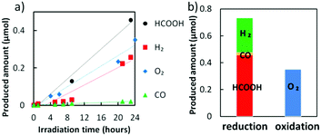
The Z-scheme system was built using a Cu–Zn NPs modified CFO as the photocathode and WO3 as the photoanode (see the schematic illustration, Fig. S1, ESI†). We applied a bias potential of −0.5 V onto the cathodic side, since only trace amounts of H2 and C1 molecules were detected under the other potential conditions without any bias application (Fig. S16a, ESI†). CO2 gas was bubbled in the cathodic side electrolyte and the anodic side was purged by N2 to remove any dissolved oxygen. Without the Cu–Zn co-catalyst, hydrogen was preferably generated rather than C1 molecules in the cathodic side (Fig. S16b, ESI†). In contrast, the production of HCOOH was significant when the optimal amount of Cu–Zn NPs was coated onto the CFO surface (Fig. 5a). The result of selective HCOOH generation was reproducible (Fig. S17, ESI†) and the faradaic efficiency achieved for HCOOH generation was 53.6–56.1%. It should be noted that the produced amount of O2 from the anodic side was almost half of the reduction products (Fig. 5b). For the generation of H2, CO, and HCOOH molecules, two electrons are needed, while four electrons are donated from water to generate O2. Therefore, it was proved that our Z-scheme system drives CO2 reduction using water molecules as electron donors, similar to photosynthesis in natural plants.
This study is the first report to achieve highly selective HCOOH generation (>50%) from CO2 photoreduction under visible light without the addition of sacrificial agents, based on inorganic robust materials. The turnover number (TON) of the Cu–Zn NPs in the present study was 12.35, even after 24 h of visible light irradiation, with a linear increase of HCOOH concentration. We have also confirmed that the Cu–Zn NPs remained stable even after 24 h photocatalytic evaluation according to our HAXPES analyses (Fig. S18, ESI†). Besides, the higher TON was recorded to be 1400 in the case of our Cu–Zn/SrTiO3 under UV irradiation.18 These results strongly suggest that our Z-scheme system is highly stable under photon irradiation in aqueous media. The quantum efficiency for the reduction products was 0.14% in our system. Our light-to-energy conversion efficiency for the full xenon lamp spectrum was calculated to be 0.028%, which is 10 times higher than that of the previous pioneering work,5 by considering the electrical bias and chemical bias from the pH difference between the cathode and the anode (see the ESI†). The cathodic surface improvement by Cu–Zn NPs was critical for the high performance of selectivity, efficiency and activity of the system. In addition, the Cu–Zn NPs proved to be a general co-catalyst which can be broadly applied to various kinds of light harvesters, due to their facile deposition under moderate conditions by using an ink method.
In conclusion, we have demonstrated that Cu–Zn alloy NPs can be utilized as a general CO2 reduction catalyst, exhibiting high selectivity for HCOOH generation. A Z-scheme system constructed from a Cu–Zn NPs decorated highly crystallized CaFe2O4 photocathode and a WO3 nanotree photoanode drove selective CO2 photoreduction through water oxidation under visible light irradiation. Our system consists of robust inorganic materials and safe, inexpensive elements. The faradaic efficiency for HCOOH generation was over 50%, and the light energy conversion efficiency reached 0.028%. These results are promising for the development of a natural plant-like, visible-light-driven CO2 photoreduction system.
This work was supported by Grants-in-Aid from the Advanced Catalytic Transformation Program for Carbon Utilization (ACT-C, Grant JPMJCR12ZG), Japan Science and Technology Agency (JST), and Japan Society for the Promotion of Science (JSPS) KAKENHI Grant Number 26410234 and 16J08808. The HAXPES measurements were performed with the approval of the NIMS Synchrotron X-ray Station (Proposal #2015A4603 and 2015B4605). We also appreciate preliminary research on WO3 nanotrees by Mr Y. Nukui.
Conflicts of interest
There are no conflicts of interest to declare.Notes and references
- X. Chang, T. Wang and J. Gong, Energy Environ. Sci., 2016, 9, 2177–2196 CAS.
- S. Chen, T. Takata and K. Domen, Nat. Rev. Mater., 2017, 2, 17050 CrossRef CAS.
- K. Iwashina, A. Iwase, Y. H. Ng, R. Amal and A. Kudo, J. Am. Chem. Soc., 2015, 137, 604–607 CrossRef CAS PubMed.
- T. M. Suzuki, T. Nakamura, S. Saeki, Y. Matsuoka, H. Tanaka, K. Yano, T. Kajino and T. Morikawa, J. Mater. Chem., 2012, 22, 24584–24590 RSC.
- R. Kuriki, M. Yamamoto, K. Higuchi, Y. Yamamoto, M. Akatsuka, D. Lu, S. Yagi, T. Yoshida, O. Ishitani and K. Maeda, Angew. Chem., Int. Ed., 2017, 56, 4867–4871 CrossRef CAS PubMed.
- K. Iizuka, T. Wato, Y. Miseki, K. Saito and A. Kudo, J. Am. Chem. Soc., 2011, 133, 20863–20868 CrossRef CAS PubMed.
- G. Yin, M. Nishikawa, Y. Nosaka, N. Srinivasan, D. Atarashi, E. Sakai and M. Miyauchi, ACS Nano, 2015, 9, 2111–2119 CrossRef CAS PubMed.
- S. Shoji, G. Yin, M. Nishikawa, D. Atarashi, E. Sakai and M. Miyauchi, Chem. Phys. Lett., 2016, 658, 309–314 CrossRef CAS.
- D. Scaife, Sol. Energy, 1980, 25, 41–54 CrossRef CAS.
- S. Chen and L.-W. Wang, Chem. Mater., 2012, 24, 3659–3666 CrossRef CAS.
- Y.-C. Pu, W.-H. Lin and Y.-J. Hsu, Appl. Catal., B, 2015, 163, 343–351 CrossRef CAS.
- J.-M. Li, H.-Y. Cheng, Y.-H. Chiu and Y.-J. Hsu, Nanoscale, 2016, 8, 15720–15729 RSC.
- K. Sekizawa, K. Maeda, K. Domen, K. Koike and O. Ishitani, J. Am. Chem. Soc., 2013, 135, 4596–4599 CrossRef CAS PubMed.
- A. Iwase, S. Yoshino, T. Takayama, Y. H. Ng, R. Amal and A. Kudo, J. Am. Chem. Soc., 2016, 138, 10260–10264 CrossRef CAS PubMed.
- G. Sahara, H. Kumagai, K. Maeda, N. Kaeffer, V. Artero, M. Higashi, R. Abe and O. Ishitani, J. Am. Chem. Soc., 2016, 138, 14152–14158 CrossRef CAS PubMed.
- E. Baytok, T. Aksu, M. A. Karsli and H. Muruz, Turk. J. Vet. Anim. Sci., 2005, 29, 469–474 Search PubMed.
- T. Arai, S. Sato and T. Morikawa, Energy Environ. Sci., 2015, 8, 1998–2002 CAS.
- G. Yin, H. Abe, R. Kodiyath, S. Ueda, S. Nagarajan, A. Yamaguchi and M. Miyauchi, J. Mater. Chem. A, 2017, 5, 12113–12119 CAS.
- S. Ida, K. Yamada, T. Matsunaga, H. Hagiwara, Y. Matsumoto and T. Ishihara, J. Am. Chem. Soc., 2010, 132, 17343–17345 CrossRef CAS PubMed.
- Y. Matsumoto, M. Obata and J. Hombo, J. Phys. Chem., 1994, 98, 2950–2951 CrossRef CAS.
- Y. Nukui, N. Srinivasan, S. Shoji, D. Atarashi, E. Sakai and M. Miyauchi, Chem. Phys. Lett., 2015, 635, 306–311 CrossRef CAS.
- H. Du, C. T. Williams, A. D. Ebner and J. A. Ritter, Chem. Mater., 2010, 22, 3519–3526 CrossRef CAS.
- K. K. Bando, K. Sayama, H. Kusama, K. Okabe and H. Arakawa, Appl. Catal., A, 1997, 165, 391–409 CrossRef CAS.
- R. Kortlever, J. Shen, K. J. P. Schouten, F. Calle-Vallejo and M. T. Koper, J. Phys. Chem. Lett., 2015, 6, 4073–4082 CrossRef CAS PubMed.
- R. P. S. Chaplin and A. A. Wragg, J. Appl. Electrochem., 2003, 33, 1107–1123 CrossRef CAS.
- A. Kondo, G. Yin, N. Srinivasan, D. Atarashi, E. Sakai and M. Miyauchi, Nanoscale, 2015, 7, 12510–12515 RSC.
- Z. G. Zhao, Z. F. Liu and M. Miyauchi, Adv. Funct. Mater., 2010, 20, 4162–4167 CrossRef CAS.
- N. Srinivasan, E. Sakai and M. Miyauchi, ACS Catal., 2016, 6, 2197–2200 CrossRef CAS.
Footnote |
| † Electronic supplementary information (ESI) available. See DOI: 10.1039/c8cc00535d |
| This journal is © The Royal Society of Chemistry 2018 |

