
Biomedical applications of mid-infrared quantum cascade lasers – a review
Katharina
Isensee
 ,
Niels
Kröger-Lui†
and
Wolfgang
Petrich
*
,
Niels
Kröger-Lui†
and
Wolfgang
Petrich
*
Kirchhoff-Institute for Physics, Heidelberg University, INF 277, 69120 Heidelberg, Germany. E-mail: wolfgang.petrich@kip.uni-heidelberg.de; Tel: +49 6221 54 9893
First published on 24th October 2018
Abstract
Mid-infrared spectroscopy has been applied to research in biology and medicine for more than 20 years and conceivable applications have been identified. More recently, these applications have been shown to benefit from the use of quantum cascade lasers due to their specific properties, namely high spectral power density, small beam parameter product, narrow emission spectrum and, if needed, tuning capabilities. This review provides an overview of the achievements and illustrates some applications which benefit from the key characteristics of quantum cascade laser-based mid-infrared spectroscopy using examples such as breath analysis, the investigation of serum, non-invasive glucose monitoring in bulk tissue and the combination of spectroscopy and microscopy of tissue thin sections for rapid histopathology.
 Katharina Isensee | Katharina Isensee received her MSc degree in physics from Heidelberg University with a specialization on optics and photonics as well as atomic- and molecular physics. In her Master thesis she worked on the hyperspectral imaging of living microorganisms in the mid infrared region, where she used a QCL-based microscope in combination with a microfluidic device. During her PhD, she specializes on the use of QCLs for quantitative spectroscopy of biofluids with a focus on the feasibility of a glucose monitoring implant for diabetes treatment. Her current research interest targets the biomedical application of QCLs for mid-infrared spectroscopy and microspectroscopy. |
 Niels Kröger-Lui | Niels Kröger-Lui received his diploma and PhD in physics from the Heidelberg University, where his research focused on quantum cascade laser-based (QCL) sensing in biofluids as well as QCL-based and Raman imaging. He subsequently worked as a postdoctoral researcher in the biophotonics group of Prof. Petrich at the Kirchhoff-Institute for Physics in Heidelberg and spun out the company IRM2 Infrarot Mikroskopie und Messtechnik GmbH, which specialized on QCL-based microscopy. In 2018, IRM2 was acquired by Bruker Optics GmbH in Ettlingen, Germany, and Niels Kröger-Lui joined Bruker Optics as Head of Laser Spectroscopy. |
 Wolfgang Petrich | Wolfgang Petrich is professor of physics at the Department for Physics and Astronomy at Heidelberg University, where he is leading the Biophotonics Team located at the Kirchhoff-Institute for Physics. Here, the biomedical applications of infrared, Raman, and fluorescence spectroscopy constitute his main research interests. In addition to his contributions to the University he is a full-time employee in the Research and Early Development department of Roche Diabetes Care GmbH, Mannheim, Germany. Wolfgang Petrich authored and co-authored more than 100 publications and patents and has been organizing multiple conferences in biophotonics. |
1. Introduction
Twenty years ago H.H. Mantsch inaugurated a series of conferences1 on “Biomedical Vibrational Spectroscopy”, which covered the topic of the application of infrared (and Raman) spectroscopy to biology and medicine. At that time, Fourier-Transform Infrared (FT-IR) Spectroscopy was the most common modality for the non-destructive, reagent-free analysis of molecular vibrations by means of infrared radiation (see e.g.ref. 2–6). The fundamental physics behind infrared spectroscopy is the change in permanent molecular dipole moment which arises from the change in the relative distances among the nuclei of a molecule. In turn, since the distances between, for example, two nuclei behave (to first order) like a harmonic oscillator, molecular bonds vibrate at an Eigenfrequency, which is susceptible to infrared radiation of the same frequency. Given the typical binding forces in a molecule and the masses of the nuclei in a molecule it turns out that these Eigenfrequencies are on the order of 10…100 THz. Electromagnetic radiation in that region is called mid-infrared (MIR) radiation.With regards to biomedical vibrational spectroscopy in the mid-infrared it has been shown that this regimen of spectroscopy is capable of, for example, quantifying molecular concentrations or assessing molecular content of tissue. The combination of mathematical methods of data analysis (see e.g.ref. 7–9) with mid-infrared spectroscopy laid the grounds for advancing the field from biological research to medical applications (see e.g. Lasch and Kneipp10).
Despite the many fruitful results, however, mid-infrared spectroscopy has not found its way into the clinical practice. Among the reasons has been the need for specialized spectroscopic know-how during operation, the cost of equipment, the necessity for sample preparation, potentially long measurement times and/or the need for liquid nitrogen cooling of the detectors. It is in particular the latter two issues which triggered the desire to use high-power sources of radiation such as mid-infrared lasers, which enable the use of room-temperature detection schemes and the reduction of measurement time. In addition to the high power, biomedical vibrational spectroscopy might also benefit from the small bandwidth of the radiation source (i.e. a high spectral power density) as well as the small angle of emission out of a small facet (Note that the product of emission angle and beam radius is determining the so-called “beam parameter product”, which is an important design parameter in optical setups whereby sources with small beam parameter products are considered highly advantageous). Another general property of laser radiation is the high degree of spatial and temporal coherence. Lasers may be operated at a fixed frequency or tuned over a wavelength range as well as they may be emitting radiation in short pulses or continuously (CW). Here we review the application of quantum cascade laser (QCL) technology to the fields of biology and medicine.
1.1. Quantum cascade lasers
In 1994, the first demonstration of lasing in a quantum cascade laser has opened up a novel access to the mid-infrared spectral range.12 Advances in semiconductor technology have enabled the production of thin layers of semiconductor materials with high precision. If multiple layers of semiconductor materials are stacked with the appropriate thicknesses, so-called quantum well heterostructures are formed. When electrons propagate through the multiple quantum wells of a QCL they can release their energy in a cascade of multiple packages of radiation, thus enabling lasing. Today, QCLs may deliver Watts of output power, can be operated continuously even at room-temperature conditions with wall-plug efficiencies of up to 21% and may be provided in almost the full mid-infrared spectral range between 3 μm and 25 μm. Starting in 2002 the spectral range has been extended to the 1–5 THz region (see also Fig. 1). While the center wavelength is subject to the choice of material types and layer thicknesses the tuning capability can be influenced by the design of the laser ranging from small tuning ranges of Fabry-Pérot (FP) devices over Distributed Feedback (DFB) resonators to external cavity (EC) systems. A comprehensive introduction to quantum cascade laser technology is provided, for example, by Jerome Faist13 (see also, e.g., ref. 11).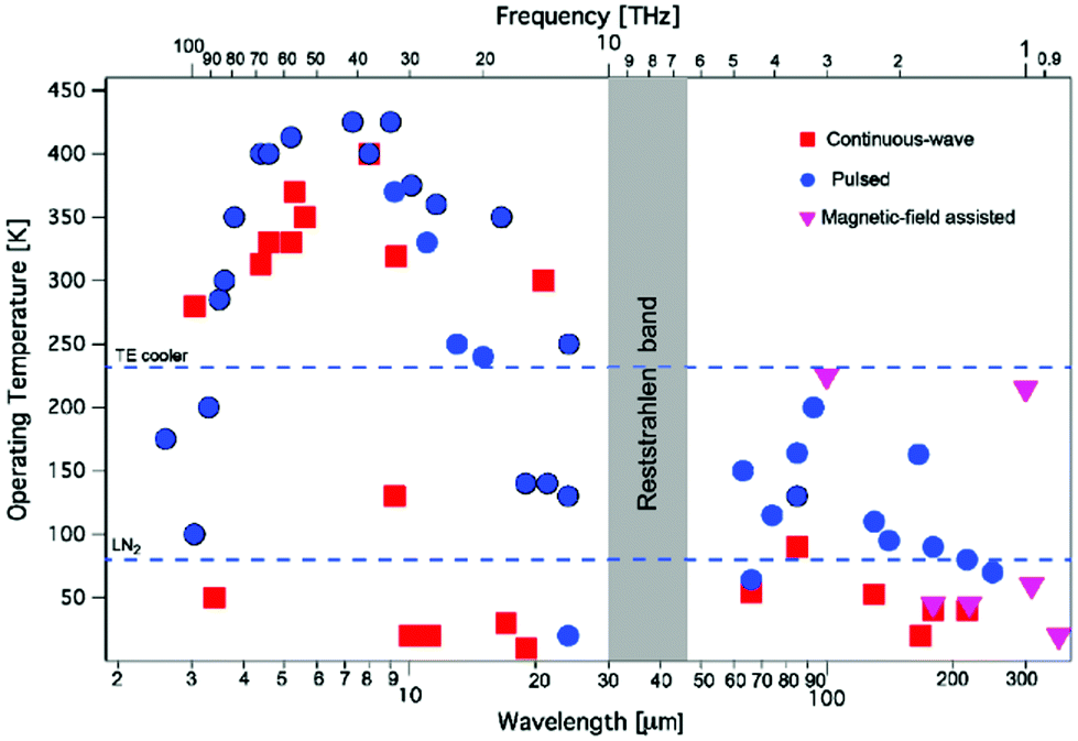 | ||
| Fig. 1 Operating temperature plot as a function of the emission wavelength (or frequency, top axis) for quantum cascade lasers. Reprinted with permission from ref. 11, The Optical Society of America. | ||
When using a narrow-band laser as a source of radiation instead of a broad-band source such as a globar, the most obvious difference in terms of measurement techniques is provided by the “host” of the spectral information: FT-IR spectroscopy, for example, is based on a broad-band source of infrared radiation and the spectroscopy is performed by introducing means for generating the wavelength information along the beam path. Such means are the scanning interferometer in FT-IR spectroscopy or the interference pattern generated by a grating in a grating spectrometer. In contrast, QCLs can be operated as narrow-band infrared sources such that the wavelength information rests in the source rather than in the beam path or detection scheme.
Standard measurement methods like transmission spectroscopy are not affected by this difference in most cases and can, thus, be readily applied to QCL-based spectroscopy. After having measured, for example, the transmission, absorption and absorbance can easily be calculated in those cases, for which scattering of the sample can be neglected.
1.2. Specimen relevant to biology and medicine
With a share of approximately 60% by weight, water constitutes the most dominant, ubiquitous molecular species in the human body. 2/3 of this water is contained in the cells, the rest is present in bodily fluids such as plasma or interstitial fluid, as well as in organs. Water also exhibits a large permanent dipole moment of 1.85 D which enables an efficient interaction with mid-infrared radiation. As an example, more than 99.8% of MIR-radiation with a wavelength of 10 μm will be absorbed in liquid water over a pathlength of 100 μm. Given the high abundance and the large dipole moment of water, mid-infrared absorbance spectra of biomedical samples are usually dominated by the spectroscopic properties of water (Fig. 2).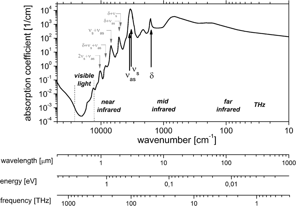 | ||
| Fig. 2 Linear Napierian absorption coefficient of liquid water (data taken from ref. 14–17 and references therein). | ||
The omnipresence of water dictates the selection of measurement technologies depending on the sample specimen:
• In gaseous samples, the concentration of water vapour is low in absolute terms but high in comparison to the concentration of other molecules under investigation. Long interaction distances are therefore required to provide access to these very dilute analytes e.g. in breath analysis. In this case it is the well suited collimation properties of laser radiation which render the use of QCLs as advantageous in this field. Enhancing the effective path length by means of a cavity has proven to be beneficial for very dilute samples, especially vapour and gases (see section 2).
• Biological liquids (see section 3) contain a large amount of water such that the detection and/or quantification of specific molecules is often hampered by the abundance of water. The reproducible drying of biofluids has proven to be a viable path towards e.g. the analysis of serum (see e.g.ref. 18–20). These “biofilms” are often investigated on diffusely scattering, reflective surfaces such that the measurement becomes a mixture of reflection and transmission techniques (“transflection”). Another strategy has been to limit the penetration depth into the medium by using attenuated total reflection (ATR)6 or the optical path length by means of thin transmission cell setups. The high spectral power density of QCLs now has opened up the access to thicker specimen and/or faster measurement times.
• The outer layer of bulk tissue (see section 4) samples can readily be evaluated by attenuated total reflection spectroscopy. If deeper layers of bulk tissue are of interest recent QCL-based measurements tend to combine MIR-spectroscopy with alternate detection methods such as the detection of acoustic waves (“photoacoustic spectroscopy” (PAS)).
• QCL-related research on tissue thin sections (see section 5) nowadays allows for rapid, spatially resolved mid-infrared spectroscopy for which, again, the high spectral power density and the beneficial beam properties of QCLs are essential. The combination of microscopy and spectroscopy is often dubbed “microspectroscopy”.
Given the varying approaches and methods for coping with the dominating contributions of water together with the specific properties of QCLs in each of the cases, this review is organized according to the specimen rather than measurement technology or field of medicine.
2. Analysis of gaseous samples
Quantum cascade laser technology has shown to be able to deliver spectra of gases almost as precise as those spectra which are obtained with FT-IR spectroscopy (for a recent example see, for example, Zhou et al.21). The majority of QCL-based gas analysis in the biomedical field focuses on breath analysis, a medical topic of increasing interest.22 Diatomic, homonuclear, and, thus, IR-inactive molecules such O2 or N2 constitute the by far dominant contribution to breath, followed by the IR-active water vapour (5%) and carbon dioxide (5%). More than 1000 further compounds can be found in breath at concentrations of less than 100 ppm. As far as MIR spectroscopy is concerned, the most abundant molecules next to water and carbon dioxide are carbon monoxide and acetone (and methane in case of carbohydrate malabsorption), followed by further molecules of interest with concentrations in the ppb-range (Fig. 3).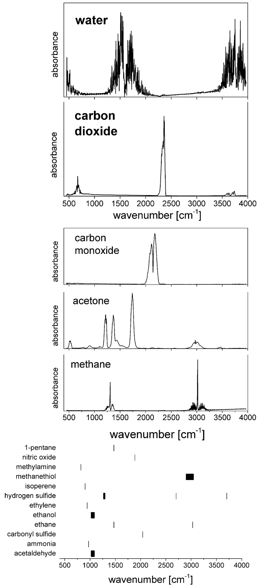 | ||
| Fig. 3 Spectral properties of molecules relevant to breath analysis. (Top) Water and carbon dioxide are the most abundant MIR-active molecules, followed by (middle) the less abundant (ppm) carbon monoxide, acetone and methane. The bottom part of the image illustrates the peak positions of molecules with concentrations in the ppb-range. | ||
While the ratio of carbon dioxide to oxygen is of fundamental interest in assessing e.g. the respiratory system, MIR spectroscopy is well suited for measuring isotope ratios of 12CO2 and 13CO2, since a change in nuclear mass selectively shifts the related molecular Eigenfrequencies. Wörle et al.23 administered 13C-rich glucose in mice and observed the concentration of 13CO2, thus providing important insights into the glucose metabolism and its conceivable dysfunctions under e.g. septic shock. By using a core hollow waveguide as gas cell and comparing the results obtained by QCL-based spectroscopy to the reference method (gas chromatography/mass spectrometry, GC/MS) the group was able to measure the so-called tracer-to-tracee ratio with a mean relative deviation as low as 3.4%. Such measurement of the isotope ratio could also be beneficial for diagnosing heliobacter pylori infection.
Carbon monoxide is considered indicative for inflammatory response while nitric oxide plays a critical role in many physiological processes and pathophysiologies. Exhaled NO is being discussed in the context of pulmonary diseases such as asthma. Simultaneous quantification of CO2, CO, NO, and N2O was achieved by Shorter et al.24 using tunable infrared laser differential absorption spectroscopy (TILDAS) with 2 QCLs and a 500 mL multipass sampling cell. An example from their measurements on breath samples originating from 22 volunteers is shown in Fig. 4. The instrumental noise limits the detection to 0.06% for CO2, 0.06 ppb for CO, and 0.2 ppb for NO (sampling rate: 10 Hz). A detection limit of 0.7 ppb for the concentration of NO is achieved in a 1 s sampling interval by Marchenko et al.25 using the laser beam originating from a current-tuned QCL in off-axis alignment to a multipass sampling cell with an effective path length of 400 m (sampling volume: 150 ml). It is of note that the authors also developed a sampling method to collect NO release from skin.
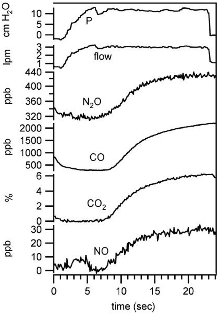 | ||
| Fig. 4 Simultaneous exhaled breath data collected from healthy male (nonsmoker) at exhalation flow of 3 L min−1. Copyright 2018 IEEE. Reprinted, with permission, from J. H. Shorter et al., IEEE Sensors Journal, 2010, 10, 76–84 (ref. 24). | ||
More recently, Katagiri et al.26 were able to reduce the sampling volume down to 18 mL by virtue of a 6 m long hollow fiber as sampling cell together with a DFB-QCL, which resulted in a detection limit for nitric oxide of 100 ppb. Since the paramagnetic nature of NO gives rise to magnetically induced birefringence, Faraday rotation spectroscopy may be used for the quantification of NO. Using a simple, robust, non-cryogenic Faraday-rotation spectroscopy6 setup, Wang et al.27 succeeded in achieving a sensitivity close to the quantum shot-noise limit for both isotopes 14NO and 15NO. Should long integration times be permissible, it is of note that the QEPAS-system (see Ma et al.28) yielded detection limits in an atmospheric research setting of 0.34 ppb and 4 ppb for CO and N2O, respectively, for an integration time of 500 s.
Multiple, independent studies have shown that there is a link between diabetes type-1 and the amount of acetone in human breath (see e.g. Wang and Wang29). Reyes-Reyes et al.30 performed initial, QCL-based investigations during overnight fasting as well as in a hyperglycemia-ketosis situation and were able to also observe the elevated average concentration of acetone in the breath of people with type-1 diabetes as compared to the healthy volunteer. Using an external cavity quantum cascade laser together with off-axis integrated output spectroscopy, Centeno et al.31 pointed out the important influence of ethanol on spectroscopic breath acetone measurements.
Elevated levels of breath ammonia are indicative for kidney disease, liver disease and further urea cycle abnormalities. The concentration of NH3 may be monitored during dialysis in patients with end-stage chronic kidney disease. Owen and Farooq32 applied wavelength modulation technique for the QCL-based quantification of ammonia in breath to patients during dialysis and found initial indications for a qualitative agreement with expectations, i.e. the relation between the concentrations of urea in blood as derived from MIR measurements and from clinical chemistry. The authors achieved a detection limit of 7 ppb. Among the further techniques employed for the QCL-based detection of ammonia in breath are cavity ring down spectroscopy, photoacoustic spectroscopy and quartz-enhanced photoacoustic spectroscopy with detection limits of 50 ppb,33 20 ppb,34 and 6 ppb.35 Manne et al.36 achieved a detection limit of 4 ppv using a current-chirped DFB-QCL at an integration time of 5 s. An EC-QCL setup was employed by Wysocki et al.37 and resulted in a detection limit below 10 ppb (time resolution: 0.5 s).
It is of note that, despite the remarkable progress in the mid-infrared spectroscopy of breath, the physiological origin of the occurrence and/or changes in concentration of molecules in breath as well as the sampling and the quest for reproducibility remain under discussion, regardless of the specific measurement technique (see, for example, ref. 38–42 and references therein.)
3. Analysis of liquid samples
Transmission spectroscopy constitutes a standard approach for the investigation of liquid samples. MIR transmission spectra can be analyzed in terms of molecule-specific absorbance bands. The technique is most suited for those cases, for which the reflection and scattering can be neglected. Application of this approach for liquid samples requires a sealed cell consisting of two infrared transmissive windows mounted at a constant distance which then defines the path length of the infrared beam in the liquid. Due to the large absorption coefficient of water in the MIR region a compromise in path length must be found between high values to increase sample specific absorption and small values to decrease noise. While, for example, Venyaminov and Prendergast17 provide general guidelines for determining the optimum pathlength for the best signal-to-noise ratio for the mid-infrared analysis of aqueous solutions, the final choice of sample thickness depends on the specific experimental conditions such as the origin of noise.The growing availability of QCLs of high spectral power density in the biological fingerprint region from 900 cm−1 to 1700 cm−1 allows for mitigating the impact of the high absorption of water.43
Several research groups have investigated the possibilities of measuring liquid samples using methods based on quantum cascade lasers as radiation source, most of which chose absorption spectroscopy in a transmission geometry or in forms of evanescent field absorption. A substantial number of publications is dedicated to the monitoring of bodily fluids in order to determine analyte concentrations (e.g. glucose). A coarse overview of the achievements in the field of quantitative analysis in provided in Fig. 5, showing that concentrations down to the 0.1 mmolar level are accessible by means of QCL-based MIR spectroscopy. More detailed information is summarized in Table 1.
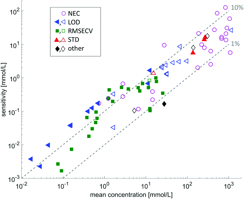 | ||
| Fig. 5 Overview on the sensitivities with respect to the mean concentration of the investigated substance. The data is extracted from the references given in Tables 1 and 2. The different symbols indicate different sensitivity ratings: LOD: limit of detection; RMSECV: root mean squared error of cross validation; STD: standard deviation of the method; other: other prediction indicators such as RMSEP, or absolute deviation from reference value. Filled symbols indicate measurements with a tunable QCL, whereas open symbols indicate measurements using a fixed frequency QCL. | ||
| Substance measured | QCL type | Spectral range/center wavelength | Environment | Path length | Concentration range | Sensitivity | Citations |
|---|---|---|---|---|---|---|---|
| Comments: PB solution: phosphate buffered solution; w. int.: with interefents; LOD: limit of detection; RMSECV: root mean squared error of cross validation; RMSEP: root mean squared error of prediction; STD: standard deviation of the method.a Value at which secondary structure of 5 different proteins is still distinguishable.b Lowest concentration used in the experiments.c With casein (3–30 g L−1), α-lactalbumin (3–10 g L−1) and β-lactoglobulin (3–15 g L−1).d With casein (0–30 g L−1) and β-lactoglobulin (0–15 g L−1).e With Na-lactate (0–244 mg dL−1), maltose (0–24 mg dL−1), xylose (0–75 mg dL−1).f With lactate (9.8–100 mg dL−1) and glucose (45–370 mg dL−1).g With glucose and mannitol (both 35–420 mg dL−1) and lactate (25–300 mg dL−1).h With galactose (0–100 mg dL−1), lactose (0–100 mg dL−1), fructose (0–100 mg dL−1) and maltose (0–450 mg dL−1).i Clinically accurate for concentrations >30 mg dL−1 with respect to Clarke error grid analysis.j Serum with added glucose.k With sodium acetate (10–40 g L−1) and glucose (10–40 g L−1).l Data adapted from NEC for glucose and the signal slope given for the substance by: NECsubstance = slopeglucose·NECglucose/slopesubstance.m With glucose (0–800 mg dL−1), maltose (0–24 mg dL−1), xylose (0–75 mg dL−1).n Absolute deviation, inferred from the data given in Lendl et al.44.o Na+, K+, Ca2+, Mg2+, Cl−, HCO3−, H2PO4−. | |||||||
| Acetic acid | Fabry-Pérot | 1393 cm−1 | Aqueous | 52 μm | 1.5–10 g L−1 | 0.19 g L−1 (LOD) | Kuligowski et al.54 |
| Albumin | EC | 1565–1729 cm−1 | PB solution | 38 μm | 1–20 mg mL−1 | 2.5 mg mL−1![[thin space (1/6-em)]](https://www.rsc.org/images/entities/char_2009.gif) a a |
Alcaráz et al.53 |
| Albumin | EC | 1030–1230 cm−1 | Blood plasma | 165 μm | 17.2–35 g L−1 | 1.2 g L−1 (RMSECV) | Brandstetter et al.55 |
| Bovine serum albumin | EC | 1565–1729 cm−1 | D2O-based PB solution | 478 μm | 0.25–2 mg mL−1 | 0.25 mg mL−1b |
Schwaighofer et al.56 |
| Albumin from chicken egg | EC | 1565–1729 cm−1 | D2O-based PB solution | 478 μm | 0.25–2 mg mL−1 | 0.25 mg mL−1b |
Schwaighofer et al.56 |
| BINOL | EC | 1220–1320 cm−1 | Deuterated chloroform | 1 mm | 150 nM | Lambrecht et al.57 | |
| Casein | EC | 1565–1729 cm−1 | PB solution w. int.c | 38 μm | 2.5–20 g L−1 | 0.8–1.3 g L−1 (RMSECV) | Kuligowski et al.58 |
| Casein | EC | 1565–1729 cm−1 | PB solution w. int.d | 38 μm | 0–30 g L−1 | 1.4 g L−1 (RMSECV) | Schwaighofer et al.59 |
| Total cholesterol | EC | 1030–1230 cm−1 | Blood plasma | 165 μm | 36–225 mg dL−1 | 20 mg dL−1 (RMSECV) | Brandstetter et al.55 |
| α-Chymotrypsin | EC | 1565–1729 cm−1 | PB solution | 38 μm | 1–20 mg mL−1 | 2.5 mg mL−1a |
Alcaráz et al.53 |
| α-Chymotrypsin | EC | 1565–1729 cm−1 | PB solution | 38 μm | 5–60 mg mL−1 | Alcaráz et al.60 | |
| Citric acid | Fabry-Pérot | 1393 cm−1 | Aqueous | 52 μm | 1.5–10 g L−1 | 0.46 g L−1 (LOD) | Kuligowski et al.54 |
| Concanavalin A | EC | 1565–1729 cm−1 | D2O-based PB solution | 478 μm | 0.25–2 mg mL−1 | 0.25 mg mL−1b |
Schwaighofer et al.56 |
| Ethanol | Fabry-Pérot | 1393 cm−1 | Aqueous | 52 μm | 4.5–100 g L−1 | 1.22 g L−1 (LOD) | Kuligowski et al.54 |
| Ethanol | Fabry-Pérot | 1032 cm−1 | PB solution | 50 μm | 10–10000 mg dL−1 |
26 mg dL−1 (NEC)l | Vrančić et al.48 |
| Fructose | EC | 1080 cm−1 | Aqueous | 165 μm | 4–99 mg dL−1 | 2.5 mg mL−1 (STD) | Beskers et al.61 |
| Fructose | DFB | 1067 cm−1 | Aqueous | 125 μm | 0–10 mg mL−1 | 390 μg mL−1 (LOD) | Edelmann et al.62 |
| Fructose | Fabry-Pérot | 1080 cm−1 | Aqueous | 52 μm | 1.25–10 g L−1 | 0.23 g L−1 (LOD) | Kuligowski et al.54 |
| Fructose | Fabry-Pérot | 1032 cm−1 | PB solution | 30 μm | 0.5–100 mg dL−1 | 12 mg dL−1 (NEC)l | Vrančić et al.48 |
| Galactose | Fabry-Pérot | 1032 cm−1 | PB solution | 30 μm | 0.5–100 mg dL−1 | 5 mg dL−1 (NEC)l | Vrančić et al.48 |
| Glucose | EC | 1030–1230 cm−1 | Aqueous | 165 μm | 4–101 mg dL−1 | 2.9 mg mL−1 (STD) | Beskers et al.61 |
| Glucose | EC | 1030–1230 cm−1 | Ringer solution w. int.e | 50 μm | 0–400 mg dL−1 | 7.3 mg dL−1(RMSECV) | Brandstetter et al.52 |
| Glucose | EC | 1030–1230 cm−1 | Serum | 135 μm | 20–120 mg dL−1 | 8.4 mg dL−1 (RMSECV) | Brandstetter et al.63 |
| Glucose | EC | 1030–1230 cm−1 | Serum spiked w. int.f | 135 μm | 40–400 mg dL−1 | 9.2 mg dL−1 (RMSECV) | Brandstetter et al.63 |
| Glucose | EC | 1030–1230 cm−1 | Blood plasma | 165 μm | 85–264 mg dL−1 | 12.2 mg dL−1 (RMSECV) | Brandstetter et al.55 |
| Glucose | DFB | 1067 cm−1 | Aqueous | 125 μm | 0–10 mg mL−1 | 360 μg mL−1 (LOD) | Edelmann et al.62 |
| Glucose | MEMS | 990–1530 cm−1 | Aqueous w. int.g | 125 μm | 35–420 mg dL−1 | 1.9 mg dL−1 (RMSECV) | Grafen et al.64 |
| Glucose | EC | 900–1205 cm−1 | Aqueous | 30 μm | 0–1000 mg dL−1 | 3 mg dL−1 (RMSEP) | Haase et al.51 |
| Glucose | EC | 900–1205 cm−1 | Aqueous w. int.h | 30 μm | 50–600 mg dL−1 | 14 mg dL−1 (RMSECV) | Haase et al.51 |
| Glucose | Fabry-Pérot | 1080 cm−1 | Aqueous | 52 μm | 1.25–10 g L−1 | 0.24 g L−1 (LOD) | Kuligowski et al.54 |
| Glucose | Fabry-Pérot | 1035 cm−1 | Aqueous | 20–100 μm | 40–400 mg dL−1 | 15 mg dL−1 (RMSEP) | Lambrecht et al.46 |
| Glucose | EC | 1000–1200 cm−1 | Aqueous, serum | 100 μm | 50–400 mg dL−1 | >30 mg dL−1i |
Liakat et al.65 |
| Glucose | DFB | 1036, 1194 cm−1 | Serumj | 26.4 μm | 50–500 mg dL−1 | 24.7 mg dL−1 (STD of mean) | Martin et al.45 |
| Glucose | Fabry-Pérot | 1080 cm−1 | Aqueous w. int.k | 41 μm | 10–40 g L−1 | 94.3% (average recovery) | Schaden et al.50 |
| Glucose | Fabry-Pérot | 1032 cm−1 | PB solution | 30 μm | 4–600 mg dL−1 | 4 mg dL−1 (NEC) | Vrančić et al.48 |
| Glucose | Fabry-Pérot | 1031 cm−1 | ISF, in vivo | 30 μm | 60–600 mg dL−1 | 7 mg dL−1 (NEC) | Vrančić et al.49 |
| Glycerol | Fabry-Pérot | 1080 cm−1 | Aqueous | 52 μm | 1.5–10 g L−1 | 0.28 g L−1 (LOD) | Kuligowski et al.54 |
| Hemoglobin | EC | 1565–1729 cm−1 | PB solution | 38 μm | 1–20 mg mL−1 | 2.5 mg mL−1a |
Alcaráz et al.53 |
| Ionso | Fabry-Pérot | 1032 cm−1 | PB solution | 30, 50 μm | 1–6193 mg dL−1 | 23–207 mg dL−1 (NEC)l | Vrančić et al.48 |
| Na-Lactate | EC | 1030–1230 cm−1 | Ringer solution w. int.m | 50 μm | 0–224 mg dL−1 | 5.7 mg dL−1 (RMSECV) | Brandstetter et al.52 |
| Sodium lactate | Fabry-Pérot | 1032 cm−1 | PB solution | 50 μm | 8–3983 mg dL−1 | 23 mg dL−1 (NEC)l | Vrančić et al.48 |
| Lactate | EC | 1030–1230 cm−1 | Serum spiked w. int.f | 135 μm | 9–90 mg dL−1 | 8.9 mg dL−1 (RMSECV) | Brandstetter et al.63 |
| Lactate | EC | 1030–1230 cm−1 | Blood plasma | 165 μm | 0.4–3.7 mmol L−1 | 0.44 mmol L−1 (RMSECV) | Brandstetter et al.55 |
| Lactate | MEMS | 990–1530 cm−1 | Aqueous w. int.g | 125 μm | 25–300 mg dL−1 | 3.1 mg dL−1 (RMSECV) | Grafen et al.64 |
| α-Lactalbumin | EC | 1565–1729 cm−1 | PB solution w. int.c | 38 μm | 2.5–20 g L−1 | 1.3–1.4 g L−1 (RMSECV) | Kuligowski et al.58 |
| β-Lactoglobulin | EC | 1565–1729 cm−1 | PB solution | 38 μm | 1–20 mg mL−1 | 2.5 mg mL−1a |
Alcaráz et al.53 |
| β-Lactoglobulin | EC | 1565–1729 cm−1 | PB solution w. int.c | 38 μm | 2.5–20 g L−1 | 0.2–0.8 g L−1 (RMSECV) | Kuligowski et al.58 |
| β-Lactoglobulin | EC | 1565–1729 cm−1 | PB solution w. int.d | 38 μm | 0–15 g L−1 | 1.3 g L−1 (RMSECV) | Schwaighofer et al.59 |
| Lactose | Fabry-Pérot | 1032 cm−1 | PB solution | 30 μm | 0.5–100 mg dL−1 | 6 mg dL−1 (NEC)l | Vrančić et al.48 |
| Limonene | EC | 1220–1320 cm−1 | Deuterated chloroform | 1 mm | 3 M | Lambrecht et al.57 | |
| Limonene | EC | 1220–1320 cm−1 | Deuterated chloroform | 1 mm | 3 M | Lüdeke et al.66 | |
| Lysozyme | EC | 1565–1729 cm−1 | PB solution | 38 μm | 1–20 mg mL−1 | 2.5 mg mL−1a |
Alcaráz et al.53 |
| Malic acid | Fabry-Pérot | 1393 cm−1 | Aqueous | 52 μm | 2–10 g L−1 | 0.38 g L−1 (LOD) | Kuligowski et al.54 |
| Maltose | Fabry-Pérot | 1032 cm−1 | PB solution | 30 μm | 1–450 mg dL−1 | 4 mg dL−1 (NEC)l | Vrančić et al.48 |
| Mannitol | MEMS | 990–1530 cm−1 | Aqueous w. int.g | 125 μm | 35–420 mg dL−1 | 2.2 mg dL−1 (RMSECV) | Grafen et al.64 |
| Ni(sp)Cl2 | EC | 1220–1320 cm−1 | Deuterated chloroform | 1 mm | 200 nM | Lüdeke et al.66 | |
| Phosphate | Fabry-Pérot | 1000 cm−1 | PB solution, diet coke samples | 106 μm | 0.01–2 g L−1 | 10 mg L−1n |
Lendl et al.44 |
| Poly-L-lysine | EC | 1565–1729 cm−1 | D2O-based PB solution | 478 μm | 0.25–2 mg mL−1 | 0.25 mg mL−1b |
Schwaighofer et al.56 |
| Proline | EC | 1220–1320 cm−1 | Aqueous | 100 μm | 3 M | Lüdeke et al.66 | |
| Total protein | EC | 1030–1230 cm−1 | Blood plasma | 165 μm | 33.7–69.4 g L−1 | 2.2 g L−1 (RMSECV) | Brandstetter et al.55 |
| Total protein | EC | 1565–1729 cm−1 | PB solution w. int.c | 38 μm | 8–37 g L−1 | 0.3–1.3 g L−1 (RMSECV) | Kuligowski et al.58 |
| Total protein | EC | 1565–1729 cm−1 | PB solution w. int.d | 38 μm | 19–36 g L−1 | 0.5 g L−1 (RMSECV) | Schwaighofer et al.59 |
| Sodium acetate | Fabry-Pérot | 1080, 1393 cm−1 | Aqueous w. int.k | 41 μm | 10–40 g L−1 | 105.8% (average Recovery) | Schaden et al.50 |
| Sucrose | EC | 1132 cm−1 | Aqueous | 165 μm | 6–103 mg dL−1 | 1.9 mg mL−1 (STD) | Beskers et al.61 |
| Tartaric acid | Fabry-Pérot | 1393 cm−1 | Aqueous | 52 μm | 5–15 g L−1 | 1.29 g L−1 (LOD) | Kuligowski et al.54 |
| Triglycerides | EC | 1030–1230 cm−1 | Serum | 135 μm | 50–500 mg dL−1 | 17.5 mg dL−1 (RMSECV) | Brandstetter et al.63 |
| Triglycerides | EC | 1030–1230 cm−1 | Blood plasma | 165 μm | 45–266 mg dL−1 | 21.5 mg dL−1 (RMSECV) | Brandstetter et al.55 |
| Urea | Fabry-Pérot | 1032 cm−1 | PB solution | 30 μm | 10–10000 mg dL−1 |
754 mg dL−1 (NEC)l | Vrančić et al.48 |
Further applications of QCLs are given by the investigation of chemical reactions such as protein conformation changes as well as the quantification of industrial productions in food industry e.g. to control of the protein content in pasteurized milk.
3.1. Transmission-based measurements
Pioneering work in QCL-based transmission measurements of liquids started around the year 2000 (see e.g. Lendl et al.,44 Martin et al.45 and Lambrecht et al.46). In various constructions, the applicability of fixed frequency QCLs for the accurate determination of analyte concentrations in bodily fluids (e.g. the concentration of glucose) was shown. Lendl et al.44 started their investigation of fluids with the use of a Fabry-Pérot QCL with an output bandwidth in the range of 20 cm−1 and compared the signal-to-noise ratios with the ones of state-of-the-art FTIR spectroscopy. Using a fiber-based transmission flow cell of variable path lengths, they gained a up to 50 times higher signal-to-noise ratio by a sample layer thickness of 106 μm compared to conventional FTIR spectroscopy (with a layer thickness of 45 μm). The method was applied to determining the phosphate content in Diet Coke using the QCL-based setup and a prediction accuracy around 15 mg dL−1 (absolute deviation from reference) was achieved.The quantification of the concentration of glucose in bodily fluids is frequently used as a benchmark for mid-infrared spectroscopy due to its importance for the management of diabetes, its accessibility via infrared spectroscopy, and the availability of established reference methods. In order to put the following examples into perspective it is important to know that the physiological concentrations of glucose in blood range from 40 mg dL−1 (2.2 mmol l−1) to 600 mg dL−1 (33 mmol l−1) whereby the range from 70 mg dL−1 (3.9 mmol l−1) to 200 mg dL−1 (11.1 mmol l−1) is considered physiologically normal. Present-day, hand-held, commercially available glucose meters provide an accuracy of 15% or better whereas laboratory methods may be as accurate as 3 mg dL−1. Physiological changes occur with rates of up to 3 mg dL−1 min−1 such that any continuous system should provide a time resolution of approximately 5 minutes or better. Multiple experiments have shown that an increase in the complexity of the matrix – i.e. from water to serum to whole blood – tends to decrease the accuracy of mid-infrared based glucose measurements. In addition, it is well known from FT-IR spectroscopy that care has to be taken when interpreting the mid-infrared spectra and even more so, when generalizing the conclusions.47
Martin et al.45 investigated the applicability for measuring glucose in diabetes treatment using two DFB QCLs with an output power of 2 mW in combination with a transmission flow cell (pathlength: 41 μm). They measured the glucose content in samples of human serum with added glucose concentrations in the range from 0 mg dL−1 to 500 mg dL−1 and, by linear regression, they gained an accuracy of 24.7 mg dL−1 (standard error of the mean).
Using also a Fabry-Pérot QCL with its emission wavelength in the relevant glucose absorbance region around 1035 cm−1 in combination with a fiber-based micro-cavity transmission sensor, Lambrecht et al.46 investigated the signal-to-noise ratio with respect to the measurement time and showed that a noise equivalent concentration (NEC) <10 mg dL−1 can be achieved (integration time: 12 s). This value constitutes an accuracy which could suffice for a monitoring of the glucose metabolism of diabetes patients.
In subsequent experiments with a similar setup, Vrančić et al.48 achieved a NEC as low as 4 mg dL−1 with glucose concentrations in the physiological range of 0 mg dL−1 to 600 mg dL−1 and with a path length of 30 μm. In a further series of measurements which targeted the continuous monitoring of glucose, Vrančić et al.49 were the first to successfully apply QCL-based spectroscopy in vivo. During measurement periods over several hours a prediction accuracy as low as 7 mg dL−1 was achieved in anesthetized rats with independent measurements every 6 seconds.
In the above mentioned experiments, the advantage of the high spectral power density of QCLs was used in order to investigate the mid-IR absorption properties of liquid samples. A potential challenge, however, stems from the presence of other substances of varying concentrations, especially if their absorption band are located in the same spectral as the analyte. Vrančić et al.48 investigated this cross-correlation for various different biological relevant substances and confirmed, that substances absorbing in the same spectral region as glucose (such as other carbohydrates) potentially impose a profound limitation to the system's glucose selectivity, whereas spectroscopically different substances (like, for example, urea) showed no influence. Although the concentration of other carbohydrates than glucose is much lower in interstitial fluid than the concentration ranges investigated in ref. 48, the generalization of QCL-based spectroscopy in vivo makes it worthwhile to explore this question in more detail.
The use of multiple wavelengths appears to be an immediate solution: in order to overcome the issue of overlapping absorption bands, Schaden et al.50 used two Fabry-Pérot QCLs at different spectral regions (1393 cm−1 and 1080 cm−1) and showed (with glucose and sodium acetate as model analytes), that the prediction accuracy of sodium acetate can be increased by a correction with the glucose concentration determined at the glucose-dominant absorption region (1080 cm−1). An alternative to this application of multiple independent QCL sources was enabled by the development of spectrally tunable QCLs using an external (macroscopic or MEMS-based) cavity (EC) QCL. Since the EC-QCLs are rapidly tunable over spectral ranges of about 80 cm−1 or even 300 cm−1, these lasers offer the possibility to better distinguish between spectroscopically similar substances. Common multivariate algorithms such as partial least square analysis (PLS) could be used for data analysis.8
Brandstetter et al.52 combined an EC-QCL which was tunable over a range of 200 cm−1 with a liquid flow cell (path length 50 μm) in order to assess the glucose selectivity in aqueous mixtures with maltose (maximum concentration: 24 mg dL−1) and xylose (maximum concentration: 75 mg dL−1). Using PLS analysis they achieved glucose prediction accuracies of 9.3 mg dL−1 (RMSEP). Haase et al.51 used a fiber-based transmission experiment with a path length of 30 μm and achieved a glucose selectivity of 14 mg dL−1 in mixtures with much higher concentrations of other saccharides (concentrations up to 100 mg dL−1 for galactose, fructose, lactose and up to 450 mg dL−1 for maltose).
In order to translate these research findings into a miniaturized, mobile and, possibly, implantable solution for continuous glucose monitoring, the question of the minimum number of wavelengths for a reliable glucose measurement must be answered. Haase et al.51 researched the potential for reducing the number of required wavelengths in the presence of further saccharides and demonstrated, that using 7 distinct wavenumber intervals (width: 1 cm−1) a glucose sensitivity of 19 mg dL−1 can be achieved. Fig. 6 provides examples for the pure component spectra of different saccharides together with the 7 wavenumbers chosen. Therefore, it appears feasible with regards to a fully implantable glucose monitoring systems, to replace the tunable QCLs with a stack of seven fixed-frequency QCLs for better mechanical stability and performance.
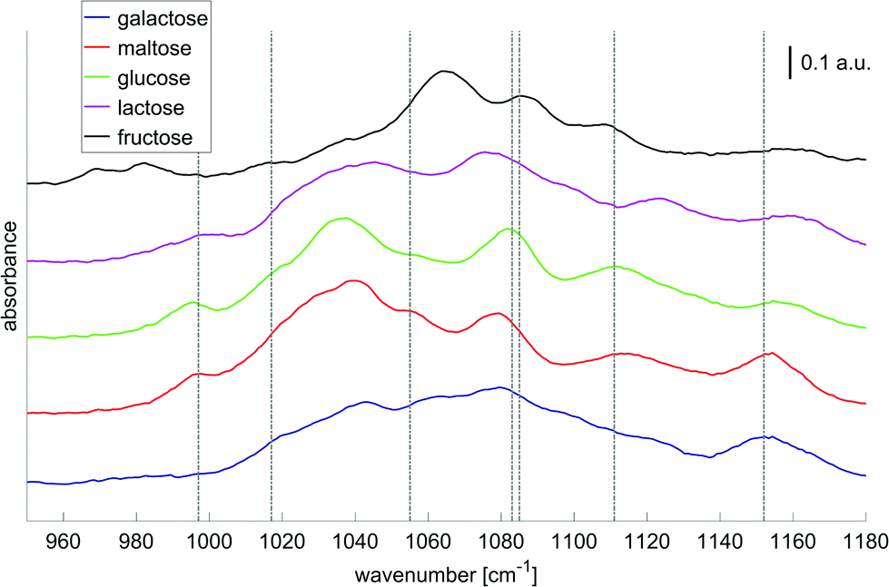 | ||
| Fig. 6 Absorbance spectra of solutions with different saccharides (concentrations: 1000 mg dL−1, averages over 80 laser sweep scans, binning 1 cm−1). The bar indicates 0.1 absorbance units. The gray dashed lines highlight the 7 wavenumbers to be important for glucose selectivity in the presence of confounding carbohydrates as derived by Haase et al.51 Adapted with permissions from ref. 51, SPIE. | ||
Since most of the experiments described above were carried out for artificial aqueous glucose solutions, Liakat et al.65 and Brandstetter et al.55 used a EC-QCL-based transmission setup in order to determine the concentration of glucose in a bodily fluid, namely serum. Liakat et al.65 spiked the serum matrix with glucose of varying concentrations (leading to spiked serum samples with glucose concentrations between 0 mg dL−1 to 400 mg dL−1) and obtained a prediction error of 30 mg dL−1. Brandstetter et al.55 determined the concentrations of different markers such as glucose, lactate, triglycerides and proteins in human blood plasma samples. Using a pathlength of 165 μm and PLS analysis, a glucose prediction error of 12.2 mg dL−1 (RMSECV) was achieved.
Besides the mentioned applications for monitoring of biological markers and disease control, QCL-based analysis of liquids finds a vast amount of applications in other areas as well (as summarized in Table 1).
Edelmann et al.62 and Kuligowski et al.54 applied QCL-based spectroscopy to the detection of products from liquid chromatography and showed their potential for analyzing wine samples.
Beskers et al.61 used EC-QCL spectroscopy for the detection of sugar concentrations whereby the different sugars were separated via high performance liquid chromatography (HPLC) prior to the MIR analysis. Using sugar concentrations of 5 mg dL−1 to 100 mg dL−1 an error of prediction of 2.9 mg dL−1 for glucose and smaller than 5 mg dL−1 for all used sugars was obtained from a linear regression model.
The group of B. Lendl53,58–60 used this approach to characterize and distinguish different proteins, to investigate conformational changes in the secondary structure of proteins, and quantify proteins in bovine milk products. Next to the different QCL tuning range (1600 cm−1 to 1700 cm−1) as compared to the measurements of carbohydrates in solutions, the experiments were performed with a cell of smaller path lengths (38 μm). With this setup, Alcaráz et al.53 demonstrated the measurement of five proteins with different secondary structures and achieved a detection limit as low as 2.5 mg mL−1 and compared the QCL-based spectra to the respective FT-IR-based spectra (Fig. 7). Schwaighofer et al.59 demonstrated the potential of ultra high protein sensitivities using D2O instead of H2O as the solvent. Because D2O does not absorb in the amid I region, the transmission path length could drastically be increased (480 μm) and the protein detection limit reaches values as low as 0.25 mg mL−1. In another experiment, Alcaráz et al.60 monitored dynamical changes between protein secondary structures with respect to varying different chemical parameters such as the pH-value. Kuligowski et al.58 and Schwaighofer et al.59 focused on the quantitative measurement of proteins in bovine milk. A PLS analysis was used for the determination of the content of casein, α-lactalbumin, β-lactoglobulin and total protein in bovine milk over the course of several minutes and prediction accuracies around 1 g L−1 (RMSECV) were achieved (concentrations of 2 g L−1 to 20 g L−1).58 EC-QCL spectroscopy was also performed for different types of commercial bovine milk (pasteurized, differently processed extended shelf life, and ultra-high temperature) and the results were compared to commonly used reference methods. This work exemplifies the prospect of EC-QCL-based spectroscopy for the fast chemometric analysis of liquids beyond the scope of commonly used standardized methods, which in the case of milk analysis involve several manual processing steps and the use of chromatographic analysis methods.59
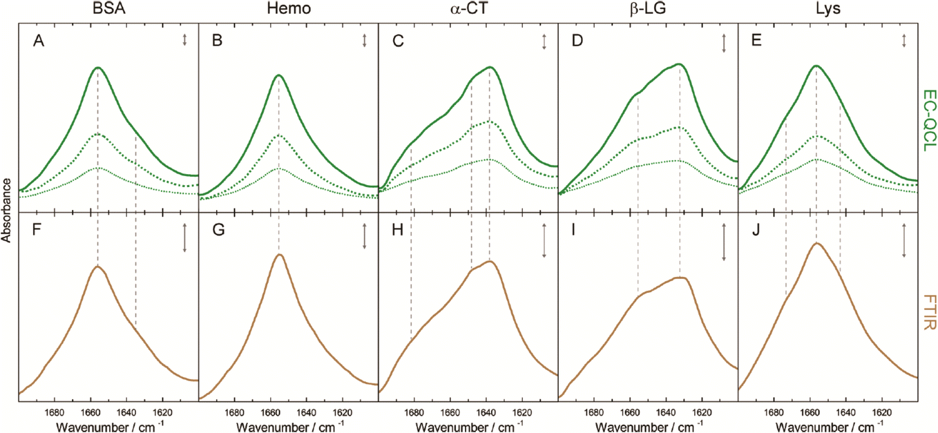 | ||
| Fig. 7 IR absorbance spectra of 10 mg mL−1 (green solid line), 5 mg mL−1 (green dashed line), and 2.5 mg mL−1 (green dotted line) protein solutions acquired by the EC-QCL setup (A–E) and 20 mg mL−1 (brown solid line) protein solutions acquired by FT-IR spectroscopy (F–J). Gray dashed lines highlight the high congruence of the spectral features between the IR spectra acquired by EC-QCL and FT-IR spectroscopy. Gray double-headed arrows indicate the absorbance of 10 mAU. Reprinted with permission from Alcaráz et al.53 Copyright (2015) American Chemical Society. | ||
3.2. Evanescent field absorption measurements
Besides the standard transmission geometry further measurements have been performed in attenuated total reflection (ATR) geometry. Here, the attenuation of a total internal reflected beam caused by the absorption of the evanescent field on a surface of a crystal is measured. It probes the sample medium at the surface reaching a penetration depth of approximately half the wavelength. While an increasing number of reflections inside the crystal increases the amplitude of the absorbance signal, it remains challenging to obtain high signal-to-noise ratios due to the low concentration of analytes in dilute aqueous solutions.Quantum cascade lasers have also proven to be a good choice for ATR measurements. Due to their small beam parameter product, the collimated laser beam can exhibit a small beam diameter and, thus, easily be coupled into ATR-crystals as well as (with the addition of appropriate focusing elements) mid-IR-transmissive fibers. Several experiments showed the prospects of combining QCL radiation sources with ATR crystals67 as well as core-only mid-IR fibers57,68–70 (see Table 2). In the latter case a mid-IR fiber core without cladding is used to measure the evanescent field absorption in its surrounding. By the use of relatively long waveguides with a adapted incidence angle, the number of reflections and thus the signal-to-noise ratio can significantly be increased.
| Substance measured | QCL type | Spectral range/center wavelength | Environment | Path length | Concentration range | Sensitivity | Citations |
|---|---|---|---|---|---|---|---|
| Bacterial cells (C. vibrioides, mammalian HEK) | EC | 1450–1720 cm−1 | Aqueous | Cimalla et al.67 | |||
| Cocaine | Not specified | 1724 cm−1 | PCE | 7 mm | 100–1000 μg mL−1 | 100 μg mL−1 (LOD) | Chang et al.,68 Wägli et al.69 |
| Cocaine | Not specified | 1724 cm−1 | Saliva | 7 mm | 100–1000 μg mL−1 | 500 μg mL−1 (LOD) | Chang et al.,68 Wägli et al.69 |
| Cocaine | DFB | 1720 cm−1 | Saliva | 7–14 mm | 100–1000 μg mL−1 | <100 μg mL−1 (LOD) | Jouy et al.70 |
| Cocaine | DFB | 1720 cm−1 | Saliva | 30 mm | 100–1000 μg mL−1 | <10 μg mL−1 (LOD) | Jouy et al.70 |
| Dichlorvos | EC | 1010–1140 cm−1 | Aqueous | 182 mm | 0–5 g L−1 | 0.15 g L−1 (LOD) | Lambrecht et al.57 |
| Glucose | Fabry-Pérot | 1010 cm−1 | Aqueous | 40 mm | 0–1000 mg dL−1 | 170 mg dL−1 (NEC) | Lambrecht et al.46 |
Chang et al.,68 Wägli et al.69 and Jouy et al.70 used evanescent field absorption in an germanium strip waveguide integrated in a microfluidic chip to detect cocaine in saliva and tetrachloroethylene (PCE) solutions. They showed that limits of detection (defined as three times the standard deviation) as low as 100 μg mL−1 can be achieved and that, by expanding the optical path length in the solution from 7 to 30 mm the limit of detection can even be decreased by one order of magnitude (10 μg mL−1).
Experiments from Lambrecht et al.57 used a core-only AgBrCl fiber with a diameter of 0.7 mm, fabricated in a coil with 10 turns and measured the content of the pesticide Dichlorvos in drinking water up to a limit of detection of 0.5 g L−1. Cimalla et al.67 determined the impact of contaminated water on bacterial cells in an ATR-geometry. These publications illustrate the potential of evanescent field-based sensing for the reliable control of drinking water.
3.3. Vibrational circular dichroism (VCD)
Based on the emission of polarized radiation, EC-QCLs hold much promise for the spectroscopic investigation of the chirality of molecules as well as for the examination of the secondary structure of biomolecules.4 In vibrational circular dichroism the difference in absorption between left- and right-circularly polarized radiation is acquired. The signal-to-noise ratio benefits from large interaction lengths of a VCD measurement but it deteriorates for too long interaction lengths with biomedical specimen due to the high absorbance of water. Again, the high spectral power density of QCLs enables to shift the signal-to-noise limitation to larger pathlength, which makes QCLs prone to be used in VCD experiments. Lüdeke et al.66 and Lambrecht et al.57 applied QCLs to the investigation of different enantiomers of chiral molecules such as limonene, proline and BINOL dissolved in deuterated chloroform and in aqueous (for proline) environment (Table 3). VCD spectra of both enantiomers of limonene may serve as an example (see Fig. 8).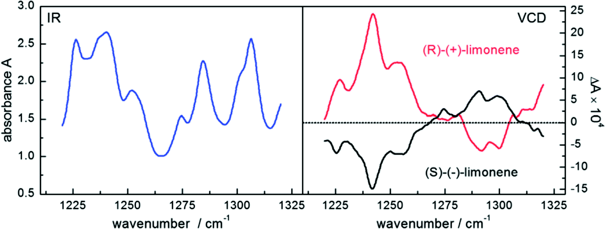 | ||
| Fig. 8 Infrared spectra (left) and vibrational circular dichroism spectra (right) of a 3 M solution of both enantiomers of the terpenoid limonene recorded with a QCL setup. Reproduced from ref. 57 with permission from the Royal Society of Chemistry. | ||
| Substance measured | QCL type | Spectral range/center wavelength | Environment | Path length | Concentration range | Sensitivity | Citations |
|---|---|---|---|---|---|---|---|
| BINOL | EC | 1220–1320 cm−1 | Deuterated chloroform (CDCl3) | 1 mm | 150 nM | Lambrecht et al.57 | |
| Limonene | EC | 1220–1320 cm−1 | Deuterated chloroform (CDCl3) | 1 mm | 3 M | Lambrecht et al.57 | |
| Limonene | EC | 1220–1320 cm−1 | Deuterated chloroform (CDCl3) | 1 mm | 3 M | Lüdeke et al.66 | |
| Ni(sp)Cl2 | EC | 1220–1320 cm−1 | Deuterated chloroform (CDCl3) | 1 mm | 200 nM | Lüdeke et al.66 | |
| Proline | EC | 1220–1320 cm−1 | Aqueous | 100 μm | 3 M | Lüdeke et al.66 |
4. Analysis of bulk tissue samples
In contrast to homogenous liquid or gaseous samples the analysis of bulk samples introduces the complication of a spatial dependence. While absorption can be inferred from transmission in homogenous samples, scattering needs to be added into this equation for bulk samples. The impact of scattering depends on the particle size, the wavelength and the (wavelength dependent) refractive indices of the structures.Since QCLs provide a small beam parameter product, a pencil-like (i.e. small in diameter but collimated) laser beam is well suited for the investigation of scattering in tissue (Fig. 9). Schönhals et al.71 investigated the scattering properties of porcine dermis by means of QCL-based goniometry in the 1030–1087 cm−1 region and could show, that
 | ||
| Fig. 9 Results of a Monte-Carlo Simulation of the propagation of mid-infrared radiation in dermis. The numerical values are based on the scattering properties of dermis as derived from the experiments by Schönhals et al.71 The vertical size of the image corresponds to a penetration depth of 250 μm. The colors represent the photon density on a logarithmic scale. Reproduced from ref. 71 with permission from the Royal Society of Chemistry. | ||
• transmission is dominated by the absorption of water. The 1/e penetration depth in porcine dermis therefore amounts to 17 μm in this wavenumber range.
• the mean scattering coefficient μs is approximately an order of magnitude smaller but not negligible. This means that the scattering probability over a distance of, for example, the above penetration depth of 17 μm amounts to 14%.
• scattering is mainly directed into the forward direction (mean anisotropy factor g = 0.967) such that – given the high absorption coefficient – backscattering from within the dermis and subsequent propagation back to the sample surface is an extremely rare event in this wavenumber range.
• the reduced scattering coefficient μ′s = μs(1 − g) is on the order of 1 cm−1 such that the total radiation being scattered back into the backward hemisphere amounts to less than 10−4 of the incoming radiation for porcine dermis.
The quest for a non-invasive detection of the concentration of glucose in skin has triggered a variety of research. Liakat et al.72 performed an initial study on three volunteers for the noninvasive detection of glucose using that part of the QCL's radiation which is backscattered from the skin. Since the penetration depth of MIR radiation in living tissue is limited by the high absorption coefficient of water and since backscattering from within the dermis is very hard to detect71 other groups have disentangled the glucose-specific signal generation inside the tissue from the detection channel. Kottmann et al.73 achieved a detection limit of 100 mg dL−1 in human epidermis in vitro by means of photoacoustic detection. Similarly, Pleitez et al.74 found initial indications for a correlation of the photoacoustic signal with the concentration of glucose in the epidermis of a volunteer. More recently, this group's efforts focused on a photothermal deflection technique75 which led to an improved understanding of the dependence of QCL-induced signals on the depth in skin in vivo.76
5. Microspectroscopy of tissue thin sections
Mid-infrared spectroscopy has been combined with microscopy for decades in the case of FT-IR spectroscopy. While FT-IR-based microscopes typically benefit from a high signal-to-noise ratio, they are often limited in terms of acquisition speed and the necessity for cooling the highly sensitive and fast Mercury–Cadmium–Telluride (MCT)-Detectors with liquid nitrogen. Although the slow acquisition speed FT-IR based infrared microscopes may be mitigated by sacrificing spectral and/or spatial resolution, it is questionable whether the technique can meet the demands of high-throughput applications. Despite the high potential of infrared chemical imaging using FT-IR based instruments and despite the long list of successful research results, FT-IR microspectroscopy has not found its way to routine applications in digital histopathology.Shortly after tunable QCLs became available, there were first attempts to use these radiation sources for infrared microscopy to overcome the limitations of FT-IR based systems. Generally, there are two paths for hyperspectral imaging in the mid-infrared spectral region using QCLs:
• a mapping approach (section 5.1) with a single element detector and a mechanical scanning of the relative position of sample and beam path or
• an imaging approach (section 5.2) using an array of detectors such as a MCT-focal plane array (FPA) detector.
It is of note that previous comparisons between synchrotron-based mapping infrared microscopes and globar-based imaging infrared microscopes can provide guidance with respect to the strengths and weaknesses of image acquisition by means of mapping: while one can achieve higher SNR using a synchrotron source in a mapping-based infrared microscope compared to using a globar source in an imaging-based infrared microscope, the imaging-based infrared microscopes outperforms the mapping-based infrared microscopes by more than one order of magnitude in terms of acquisition speed.77 However, for the case of QCL-based microspectroscopy each of the two strategies has its unique advantages and disadvantages depending on the specific application as will be exemplified in the following.
5.1. Mapping
QCLs can easily be integrated in a mapping-based setup for image acquisition. The small beam parameters product and the high brilliance of QCLs allow for large optical flux while working with small apertures. Since EC-QCLs serve as narrow-band but tunable radiation sources, hyperspectral datasets can be acquired by successively recording images at discrete wavelengths.In 2016, Tiwari et al.78 investigated the QCL-based mapping of fibrosis in unstained cardiac tissue thin sections with respect to the potential for discrete wavelength mapping for use in digital histopathology. The authors focused on development and classification of supervised Bayesian classifiers, trained on spectra (900–1800 cm−1) from FT-IR or QCL-based instrumentation, which were then used on datasets acquired with the QCL-based mapping infrared microscope. Several classifiers were developed in order to distinguish between myocardium and fibrosis. A first analysis generated a Bayesian classifier based on FT-IR hyperspectral data of tissue thin section originating from 35 anonymized patients using 13 selected spectral features (such as peak ratios). A second Bayesian classifier was built using the 14 patient samples’ spectra acquired with a QCL-based mapping infrared microscope. A total of 11 features was found to be important for decision making. In a third step, the authors focused on identifying that single spectral feature which led to the best separation between myocardium and fibrosis, whereby it was found that the absorbance ratio of amide III (1236 cm−1) to amide I (1542 cm−1) was best suited for detection of high extracellular matrix deposition. A classifier was built based on this metric by introducing a threshold value to distinguish between myocardium and fibrosis. Classification results on three different samples using FT-IR based classifier, QCL-based classifier and single metric classifier can be seen in Fig. 10. Performance of the classifiers was evaluated by comparison to the gold standard, i.e. pathologically annotated, stained serial tissue thin sections, of independent validation sets (i.e. either the entire dataset acquired with the QCL-based microscope in case of the FT-IR based classifier or an independent subset of the full dataset, which did not overlap with the training set in case of the QCL-based classifier), which resulted in an overall accuracy of 94.42% for the FT-IR based classifier, 90.99% for the QCL-based classifier and 87.5% for the single feature classifier. The performance of the single metric classifier is remarkable, since absorbance was only to be probed at 6 discrete wavelengths for calculation of the metric, allowing for rapid detection of tissue scarring in an initial analysis step. Tiwari et al.78 conclude that the high accuracy of the FT-IR based classifier may generally be suitable to be used on datasets acquired with QCL-based mapping infrared microscopes. Furthermore the authors were able to significantly reduce measurement time for the identification of tissue scarring by using a reduced amount of wavelengths for analysis.
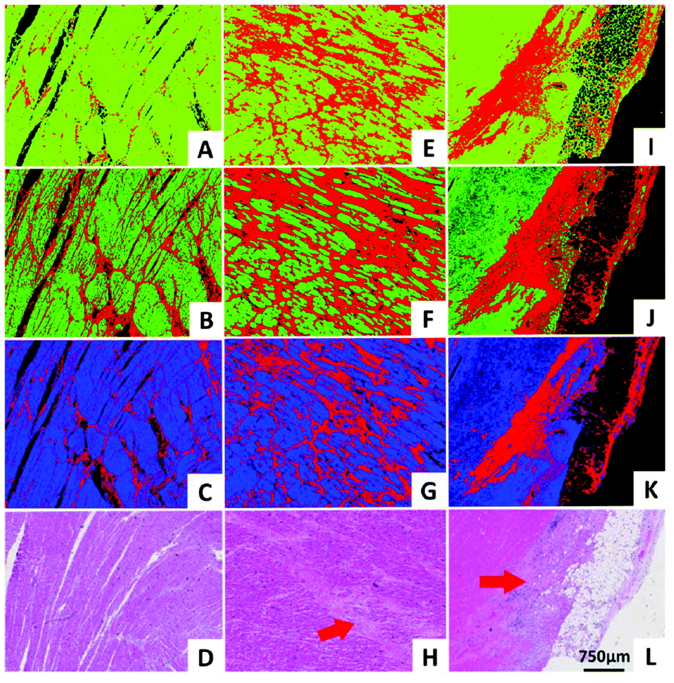 | ||
| Fig. 10 Classification results shown for MIR images of three different samples at discrete frequencies. (A, E, I) Classifier developed on FT-IR data. (B, F, J) Classifier developed on QCL-based data. (C, G, K) Single metric identification of fibrosis. Red regions in all the IR colored images are fibrosis. Corresponding H&E images are shown in (D, H, and L). Red arrows indicate the regions identified by the pathologist as fibrosis. Reprinted with permission from Tiwari et al.78 Copyright (2016) American Chemical Society. | ||
The linear polarization of the radiation emitted from QCLs allows for polarization-dependent measurements in order to visualize the orientation of macromolecules. Wrobel et al.79 used a QCL-based mapping infrared microscope in combination with a single element bolometer in order to elucidate the potential for rapid visualization of macromolecular orientation. Scanning of the sample was performed using a lateral step size of 5 μm. Acquisition of absorbance images of large samples areas (12.5 mm × 13 mm) took only ∼5 minutes for a single wavelength. Additionally, the authors were able to choose the polarization of the QCL-radiation used for illumination. The absorbance of a poly(ethylene glycol) (PEG) film was measured in the 1400–1500 cm−1 spectral region (Fig. 11a), in 5 cm−1 steps. The authors focused on the absorbance ratio of 1410:1415 cm−1, originating from the CH2 wagging vibration (Fig. 11b) whereby this vibration is influenced by the local microstructure, such that typically a red-shift of the CH2 wagging vibration is observed when transition from amorphous to semi-crystalline phase occurs. The authors clearly demonstrated the dependency of the absorbance ratio signal on polarization by imaging the PEG film for 5 different polarizations of the illuminating QCL-radiation (Fig. 11).
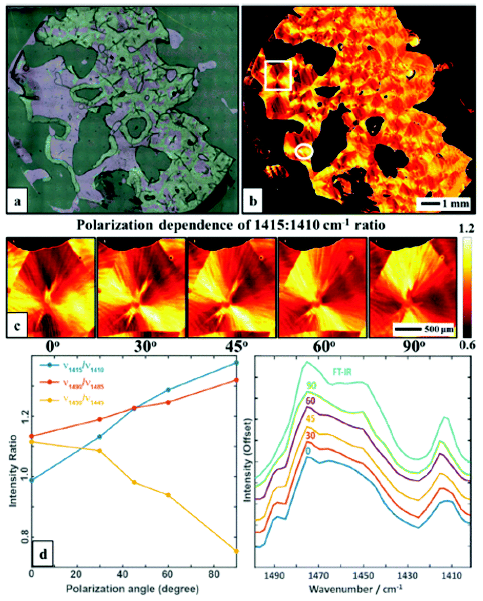 | ||
| Fig. 11 (a) Optical microscopy image of a polyethylene glycol polymer film. (b) Intensity map of 1415: 1410 cm−1 ratio at 0° polarization visualizing the spherulite crystal structure. (c) A zoom of area in the white box in b, taken with5 polarizations: 0, 30, 45, 60 and 90, respectively. (d) Polarization dependence of selected bands ratios. (e) Average spectra in the 1400–1500 cm−1 range of a selected region (white circle) taken with different polarizations and compared to a FT-IR spectrum of the same sample. The spectra have been offset for clarity. Reproduced from ref. 79 with permission from the Royal Society of Chemistry. | ||
The spectra acquired in the 1400–1500 cm−1 spectral region show similarity to the reference measurement which was acquired with a FT-IR microscope (Fig. 11e). Furthermore, a comparison between the QCL-based mapping infrared microscope and a FT-IR based infrared microscope was conducted using a SU-8 USAF 1951 target (Fig. 12). Wrobel et al.79 concluded that images acquired with the QCL-based mapping infrared microscope did not exhibit strong diffraction on edges as it is observed for the case of a widefield imaging configuration (see Kole et al.,80 Yeh et al.,81 Schönhals et al.82). Furthermore, single pixel spectra of the test target acquired with the QCL-based mapping infrared microscope showed good agreement with reference spectra acquired with a FT-IR microscope. While the QCL-based mapping infrared microscope also offers a lateral resolution which is comparable to a FT-IR microscope, the signal-to-noise ratio of the QCL-system was lower than that of a (linear-array) FT-IR imaging system presumably caused by power fluctuations of the QCL and detector noise.
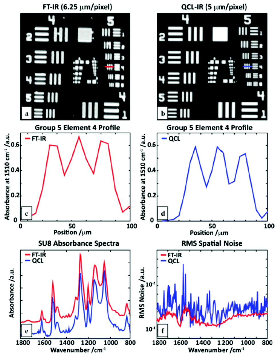 | ||
| Fig. 12 An SU-8 USAF1951 target image at 1510 cm−1 obtained using a (a) linear-array FT-IR imaging system, and (b) a QCL microscope. A line profile of element 4 of group 5 measured with (c) the FT-IR, and (d) QCL microscope. (e) A comparison of single pixel polymer (SU8) absorption spectra. (f) Root-mean-squared (RMS) values of the absorbance in a region without sample (100% line), calculated for the full QCL spectral range. Reproduced from ref. 79 with permission from the Royal Society of Chemistry. | ||
In a further investigation Wrobel et al.79 were able to illustrate that measurements at a single wavenumber and two polarizations may suffice to visualize macromolecular orientation at high acquisition speed: mapping of macromolecular orientation of the sample shown in Fig. 11a would require 1620 minutes for two polarizations using a FT-IR based infrared microscope, while the same can be done in about 9 minutes using the single-wavenumber QCL-based mapping at two polarizations, thus giving a speed advantage of a factor 180.
Mittal et al.83 reported on a custom built, QCL-based mapping infrared microscope which – to the best of our knowledge – represents the current state-of-the-art. A liquid nitrogen cooled single element MCT enables detection, while the sample is illuminated with radiation originating from four broadly tunable QCLs (770–1940 cm−1). A confocal setup was used in order to reject out-of-focus light and mitigate laser speckle. In order to further maximize signal-to-noise, the authors developed an automated algorithm to keep the sample in focus in real time, while also correcting for chromatic aberrations. When changing the wavelength of the QCLs, laser pointing alignment was performed with a galvanic beam steering system. Additionally, pulse parameters for laser operation were optimized for each wavelength individually to ensure maximum laser stability. Using high NA objectives (NA = 0.56 and NA 0.85), diffraction limited resolution of 4 μm and 3 μm (3 μm and 2 μm after deconvolution) can be achieved, while the systems acquires images with 2 μm and 1 μm pixel size respectively. An impressive spectral absorbance noise as low as 10−4 was achieved for images with 2 μm pixel size. The authors demonstrate the capabilities of their setup by investigating breast tissue samples.
One general drawback of mapping infrared microscopes is the relatively small acquisition speed when compared to imaging infrared microscopes. This drawback can be somewhat mitigated if the number of spectral data points in a measurement can be reduced, while maintaining sensitivity and specificity. Therefore, the authors analyzed breast tissue micro arrays using FTIR microspectroscopy and standard histopathology in order to identify a subset of spectral metrics (e.g. features such as peak ratios) which allow to correctly annotate each pixel with one of up to six labels, including benign and malignant epithelium. It has been shown that maximum annotation accuracy can be accomplished by acquiring infrared microscopy images at no more than 12 distinct wavelengths, which are thought to be characteristic for the identification of specific tumors in breast tissue. In comparison to a state-of-the-art FTIR imaging microscope, the authors show a 50-fold reduction of time for obtaining a decision-ready image over a complete tissue micro array. Reduction of the number of wavelengths in turn enables the analysis of needle biopsy samples in clinically feasible time frames when using the custom built QCL-based mapping infrared microscope. It is important to emphasize that both signal-to-noise and high resolution of the custom build QCL-based microscope appear to be vital to correctly analyze the tissue samples with such a limited number of spectral data points.
5.2. Imaging
For imaging, the spatial information is provided by means of imaging the sample onto a detector array rather than changing the relative position between sample and illumination/detection beam path of the infrared radiation. While MCT detector arrays constitute one option for infrared microspectroscopy, the high spectral power density of QCLs as a radiation source provides the opportunity to use cheaper, room-temperature-operated microbolometer arrays which also offer a higher number of pixels. It is of note that signal-to-noise ratios of uncooled microbolometer array detectors improved dramatically over the last decades: an important measure for noise performance for thermal cameras is the so-called Noise Equivalent Temperature Difference (NETD). Uncooled microbolometer detectors are readily available with a NETD as low as 30 mK. The typical pixel pitch of an uncooled microbolometer array detector is 25 μm or 17 μm for more recent devices.84 Hence, uncooled microbolometer array detectors can compete with MCT-FPA detectors both in terms of NETD as well as pixel pitch. Microbolometer array detectors typically have a frame rate of 20–60 Hz and array sizes of 640 × 480 pixels.84 Albeit the substantially larger intrinsic time constant of microbolometer detectors (as compared to MCT detectors), the sub-second time for acquiring an image in combination with the high spectral power density of a QCL should allow for very fast hyperspectral analysis of thin tissue sections.Phillips and Hô85 were the first research group to demonstrate the general potential of QCLs as a radiation source for imaging based infrared microscopy. It has been demonstrated that, by combining a tunable ECQCL with refractive optics and an uncooled microbolometer array detector, a fast infrared microscope can be realized. The setup was capable to distinguish between methanol and ethanol with a field of view of 40 × 30 mm and a pixel size of 125 × 125 μm2, using an uncooled microbolometer array detector with 320 × 240 pixel (Fig. 13).
 | ||
| Fig. 13 Chemical imaging of sample containing methanol and ethanol liquid. (a) Three absorbance spectra from different points in the hyperspectral image, showing mostly methanol (green), mostly ethanol (blue) and a mixture of both (red). (b) Absorbance spectra of pure liquid methanol (green) and pure liquid ethanol (blue) obtained using the ECQCL system and a point detector. (c) Methanol concentration (fit coefficient) obtained by a least-squares fit of the reference spectra. (d) Ethanol concentration obtained by the same method. Reprinted with permission from ref. 85, The Optical Society of America. | ||
Later studies confirmed the potential of the technique for chemical imaging with higher resolution by demonstrating the capability to distinguish between small particles of explosive compounds RDX, tetryl and PETN.86
Hughes et al.87 published studies on dried serum samples using a QCL-based imaging infrared microscope for high throughput biofluid screening for early diagnosis of different cancer types. While, at first sight, it is not obvious why QCL-based imaging infrared-microscope would outperform the achievements of FT-IR based, non-microscopic analysis of dried serum spots (see, for example, ref. 18–20, 45, 88 and 89), Hughes et al.87 exploited the lateral resolution of the QCL-based imaging infrared microscope to exclude pixels with saturated data (caused by the varying sample thickness within each dried serum spot) from further analysis. In a proof of concept study the authors demonstrated, that the relative standard deviation between spectra acquired from dried serum samples is 0.6, 5.1 and 15% for 199, 14 and 9 discrete wavelengths, respectively. Using support vector machines, 40 serum samples of patients with different types of cancer were classified against a control group of 10 non-cancer patients with an accuracy of up to 90%. Further research is aiming to leverage the potential of microspectroscopy in the analysis of spotted, dried biofluids.
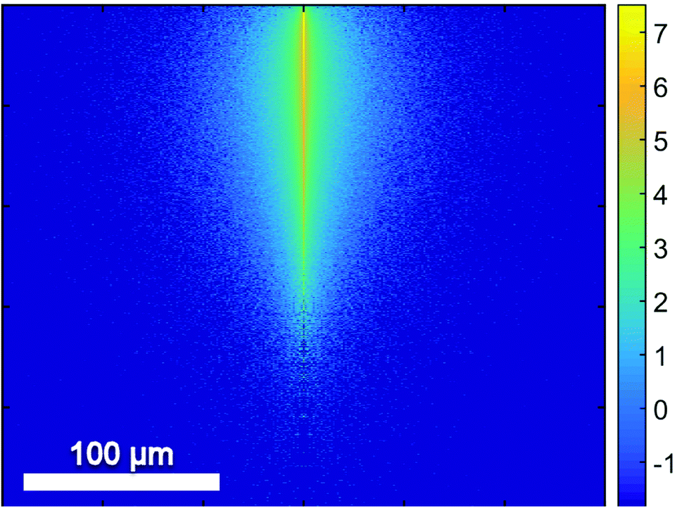
Unlike a globar, QCLs have a high relatively high degree of temporal and spatial coherence. When using a QCL as radiation source in a wide-field setup for imaging-based infrared image acquisition with an FPA detector, coherence of the source poses a major challenge for chemical imaging. The coherence of the QCL is adding to the general disadvantage of imaging compared to mapping in terms of signal-to-noise ratio and resolution. Because of this, the applicability of QCL-based infrared microscopy based on imaging without coherence-reducing techniques was initially questioned. It remained particularly unclear, to which degree a wide-field infrared microscopy using a QCL can also be used for chemical imaging of strongly scattering samples with domain sizes on the length scale of a single wavelength. This question was first addressed by Kole et al.80 using a custom build setup with a tunable narrow-bandwidth QCL and an uncooled microbolometer array detector as well as, optionally, a cooled MCT-FPA.
Kole et al.80 anticipated the presence of interference signals caused by the high degree of coherence of QCLs. Signals caused by high coherence such as fringes and speckles are generally not to be confused with noise. Kole et al.80 observed interference signals by imaging a resolution test target at discrete wavelengths and by comparing the results to those acquired with a commercial FT-IR infrared microscope. The group also attempted to mitigate the effects caused by coherence by adding a rotation diffuser plate to the beam path. It is apparent from the results shown in Fig. 14, that the results obtained with the QCL-based microscope both with and without diffuser blade deviate significantly from the reference measurement done with an FT-IR based microscope. When illuminating with a QCL, a fine structure in absorbance images caused by interference of scattered and transmitted waves at two different points can be noticed. The authors concluded that – while images of an optical resolution target acquired with the QCL-based imaging infrared microscope are comparable to FT-IR based measurements in terms of spatial resolution – the results lack spectral clarity and signal-to-noise ratio. The authors acknowledged the potential of QCL-based imaging infrared microscopes for “qualitative imaging” and that it might “…reasonably correlate with FT-IR imaging data, provided that absorbance is high and scattering is not especially strong…”.80 Kole et al.80 also concluded that “…for weak absorbance and domain sizes on the order of the wavelength, results between the two would deviate significantly…” and that – given further improvements to QCL-based instruments are made – “…QCL-bolometer system will offer advantages over FT-IR imaging for certain applications…”.
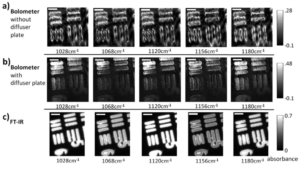 | ||
| Fig. 14 USAF 1951 optical resolution target absorption images (cycle 3, elements 5 and 6) as acquired by three different instruments. (a) QCL + bolometer system without diffuser plate. (b) QCL + bolometer system with rotating diffuser plate. (c) Commercial FT-IR instrument. Please note the differences in the color bars between the three sets of images. The scale bar in the images denotes 100 μm. Reprinted with permission from Kole et al.80 Copyright (2012) American Chemical Society. | ||
In 2014, several papers were published that highlighted the ongoing improvements of QCL-based imaging infrared microscopy. Kröger et al.90,91 reported on a custom built QCL-based imaging infrared microscope which effectively diminished the effects of coherence by reducing the time-averaged spatial coherence.82 This seminal application of QCL microscopy to the investigation of biomedical tissue (Fig. 15) showed good agreement between FT-IR mapping and QCL imaging.90,91 A direct comparison between the two methods and using the identical samples clearly showed the superiority of the QCL-imaging with regards to acquisition time and without sacrificing spatial nor spectral resolution.90 Kröger-Lui et al.92 later reported on the rapid identification of goblet cells in colonic mucosa of mouse colon tissue, using the same custom-built setup as a basis. By multiplexing two EC-QCLs, the microscope was able to operate in the spectral range of 1027–1087 cm−1 and 1167–1319 cm−1. The field of view of the system was 3.1 × 2.8 mm2, with a pixel size of 3.65 μm. Spectra were recorded with an acquisition time of about 5 minutes. Recording of spectra of a training set sample allowed for training a random forest classifier for the classification of spectra of a separate validation set (Fig. 16). It was further demonstrated that by recording the absorbance of the samples at only two discrete wavelengths, regions of high mucin concentration such as conglomerates of goblet cells could be identified, cutting down the acquisition time to well below one minute (Fig. 17b). The results correlate well with traditional light microscopy after straining the tissue sample with Alcian blue & PAS, which is commonly used to differentiate between infectious colitis and an inflammatory bowel disease such as ulcerative colitis. This was the first report on a QCL-based imaging infrared microscope that was not only capable to accurately distinguish between different tissue types of colon tissue but also between different cell types in colonic epithelium.92
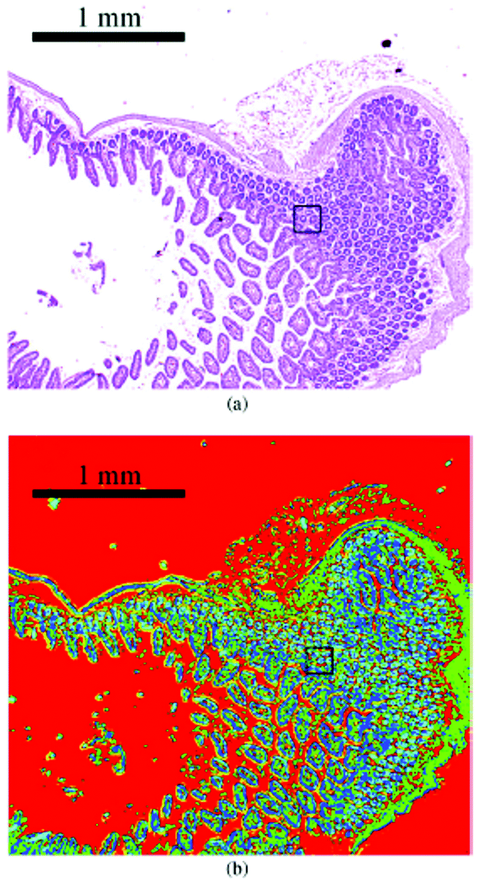 | ||
| Fig. 15 Image of haematoxylin and eosin-stained section of mouse jejunum. The center of the slice shows villi surrounded by crypts and smooth muscle tissue of the lamina muscularis. (b) Corresponding infrared label image of the adjacent unstained tissue slice, measured with QCL-based imaging. The total acquisition time of the complete infrared image of 3.1 × 2.8 mm2, including the reference measurement, amounted to 5 min. The box indicates the area used for comparing the QCL-based imaging with other infrared methods (see Fig. 3 in ref. 90). The clustering was performed in the spectroscopic region from 1030 to 1090 cm−1. Reproduced from Kröger et al.90 with permission from SPIE. | ||
 | ||
| Fig. 16 a (a)–(c) Microscopic image of a H&E stained colon slice (left column), an unstained colon tissue slice (central column), and label images obtained via k-means clustering of infrared data of the training set (right column). For the images of H&E stained and unstained slices, (a)–(c) represent optical zoom steps, with the magnified area highlighted by a box. The corresponding series of label images results from a digital zoom. Goblet cell rich regions in crypts are labeled green (marked by circle). (d) The mean cluster spectra obtained by clustering. Dotted lines represent the average spectra for clusters which were assigned to the paraffin background. Reproduced from ref. 92 with permission from the Royal Society of Chemistry. | ||
 | ||
| Fig. 17 QCL-based images of unstained colon tissue resulting from the analysis of infrared data. (a) The ratio of absorbances at 1076 cm−1 and 1181 cm−1 is representative for mucin and goblet cells. (b) The integral of absorbances in the wavenumber region between 1027 cm−1 and 1087 cm−1 is assigned to lamina muscularis, lamina propria, colon enterocytes. Reproduced from ref. 92 with permission from the Royal Society of Chemistry. | ||
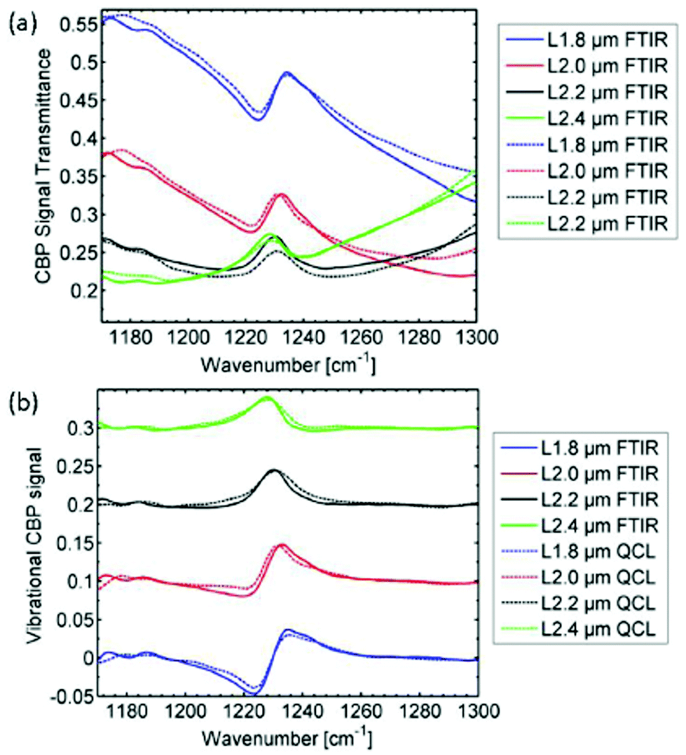
Using the same QCL-based imaging infrared microscope, Hasenkampf et al.93 conducted measurements of gold nanoantenna arrays for surface enhanced mid-infrared absorption spectroscopy (SEIRA). Since the radiation of EC-QCLs is typically linearly polarized, surface enhanced spectroscopy was enabled by aligning the nanoantenna arrays with the polarization of the illumination beam. It was found that the SEIRA signal from a thin layer of 4,4′-bis(N-carbazolyl)-1,1′-biphenyl (CBP) molecules acquired with the QCL-based imaging infrared microscope was comparable in spatial and spectral resolution to a commercial FT-IR based mapping infrared microscope (Fig. 18). This result shows the evolution of QCL-based imaging infrared microscopes, since the SEIRA signals of interest were conceptually rather small. With the parameters used for the QCL-based imaging infrared microscope for this study, the typical standard deviation from the 100% line in a single pixel was below 1%. Still, the measurement time using the QCL-based imaging infrared microscope was only 5 minutes compared to 16 hours using the FT-IR based mapping infrared microscope.93
 | ||
| Fig. 18 Mid-infrared spectra (FT-IR as well as QCL-based spectroscopy) originating from for several arrays of nanoantennas with different lengths L covered with a 5 nm thick film of 4,4′-bis(N-carbazolyl)-1,1′-biphenyl (CBP). The individual measurements have been baseline corrected and vertically offset for better illustration. The CBP mode at 1230 cm−1 has clearly the same characteristics in both the FTIR spectrum and QCL spectrum. Reprinted with permission from ref. 93, The Optical Society of America. | ||
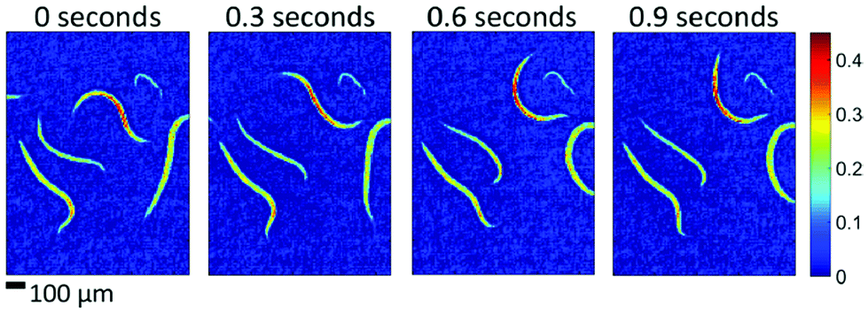
Since QCL-based imaging infrared microscopes typically operate without an interferometer, image acquisition rates are usually limited by the frame rates of the FPA detector. It is therefore possible to monitor dynamic processes in the mid-infrared spectral region in real time. Haase et al.94 demonstrated the potential of a custom built, QCL-based imaging infrared microscope to investigate liquid samples in a flow cell with layer thicknesses of up to 100 μm. Consecutive hyperspectral datasets were acquired for chemical imaging of the concentration of carbohydrates and alcohol during a fermentation process over the course of several hours.94 In a further publication, Haase et al.95 reported on the first implementation of QCL-based imaging in real time at VGA format. The authors successfully recorded single-frequency 640 × 480 pixel videos of living microorganisms such as caenorhabditis elegans in a liquid cell in real time, i.e. with frame rates of 50 Hz (Fig. 19).95
 | ||
| Fig. 19 Absorbance images of living caenorhabditis elegans in aqueous solution at different points in time. The four examples show single-frame, raw (i.e. no averaging, no smoothing) images recorded within 20 ms intervals each (wavenumber of 1265 cm−1). Reproduced with permission of Haase et al.,95 John Wiley and Sons. | ||
Bassan et al.96 reported on measurements with a commercial QCL-based imaging infrared microscope to visualize a breast tissue micro array (TMA) at 1655 cm−1. The size of the TMA was 2 × 2.4cm2, yet the acquisition time for the image was as low as 9 minutes, since absorbance was only probed at one wavelength.96 These results underlined the potential for fast chemical imaging of biological tissue using QCL-based systems, especially when only few key wavelengths are needed to visualize the features of interest of the sample.
A further application case is the use of QCL-based imaging infrared microscopes for detection of chemical changes in liver fibrosis as reported by Sreedhar et al.97 The authors demonstrated that hepatocytes and areas of fibrosis can clearly be separated in a liver tissue biopsy (Fig. 20) by measuring the absorbance at 1656 cm−1 and 1032 cm−1. This could implicate that QCL-based infrared microscopy may be an efficient tool for monitoring of the effects of anti-fibrosis treatments, since only few wavelengths have to be probed to access fibrosis, allowing for high-throughput analysis of large sample areas. However, the authors also observed a high degree of intra-class variance among spectra attributed to hepatocytes, which is a “…source of concern as it can mask important spectral variance for disease typing in a similar fashion to what was found in early work using IR spectroscopy of exfoliative cervical cytology…”.97 The authors speculate that the main two sources for the large variance between the spectra is caused by “…accumulation of glycogen in the liver as part of glucose homeostasis (which might be affected by diabetes)…”97 and “contributions from clear cell inclusion caused by liver disease…”.97 The authors reported that they were able to distinguish between low-grad and high-grade liver disease status in patients, regardless of their diabetic status.97 Given the observations it will be interesting to learn whether the interpretation of results might benefit from the findings of Kole et al.80 and Schönhals et al.82 with regards to coherence, thus allowing for further discussions on spectral variance of the measurements on hepatocytes.
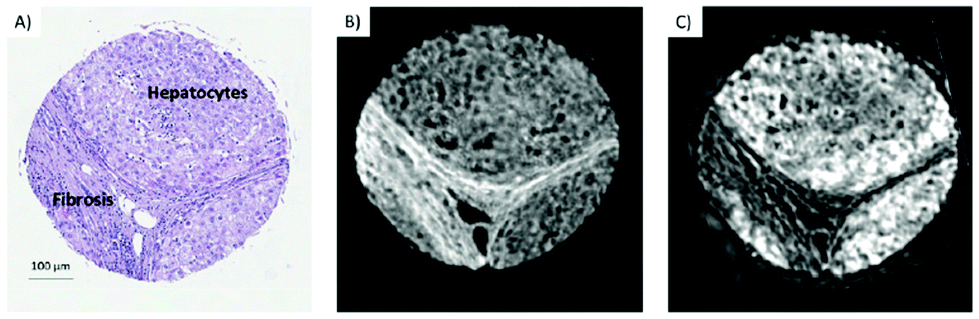 | ||
| Fig. 20 (A) H&E-stained section from a liver tissue biopsy, with regions of hepatocytes and areas of fibrosis indicated. (B) An unstained section from the same biopsy scanned in IR, presenting absorbance at 1656 cm−1. (C) Same section as in (B), presenting absorbance at 1032 cm−1. Reprinted with permission from ref. 97, The Optical Society of America. | ||
Pilling et al.98 reported on a proof of principle study using a QCL-based imaging infrared microscope for diagnosis of prostate cancer based on machine learning algorithms. The group acquired hyperspectral datasets of 50 TMAs taken from 29 cancer patients, whereby half of tissue microarray (TMA) cores was cancerous epithelium. In order to train a random forest classifier to distinguish between spectra of healthy and malignant tissue, spectra from both a healthy and a malignant tissue cores of two patients were taken as training database (Fig. 21).98 Half the spectra of the training database were randomly selected for training of a random forest classifier, while the other half of the spectra was used for subsequent validation. After training of an initial classifier using the full spectra (1000–1800 cm−1, excluding 1350–1500 cm−1 because of paraffin signatures), wavelengths were ranked using a Gini importance99 plot in order to select the key 25 wavelength which are most significant to distinguish between healthy and cancerous epithelium.
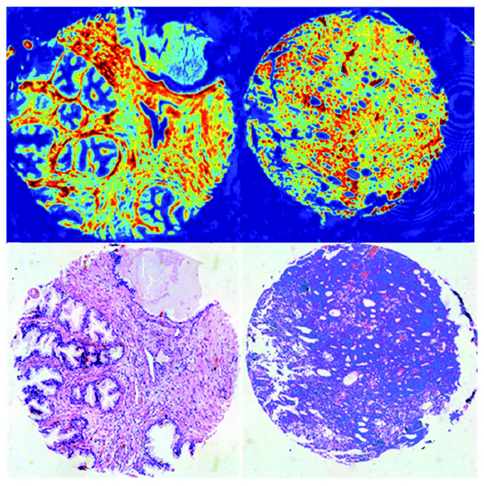 | ||
| Fig. 21 QCL chemical images of the amide I band intensity and H&E-stained serial section (bottom) for normal-associated tissue (left) and cancerous tissue (right) used to identify the key wavenumbers for discrete frequency classification. Reproduced from ref. 98 with permission from the Royal Society of Chemistry. | ||
The random forest classification algorithm was evaluated using an independent validation data set. The performance was enumerated in forms of the area under the receiver operator characteristics (AUC),100 whereby a value of 50% represents a random assignment to classes and 100% constitutes the best conceivable value of AUC. When training the random forest classifier with 25 or 10 wavelengths, the AUC amounted to 0.8395 or 0.7808, respectively. Further studies are needed to reevaluate the potential of this technique using considerably larger patient numbers for the training set in order to account for the inter-patient variability. Also, the choice of key wavelength will be more robust when using larger patient numbers, since only samples of only 2 patients were used to identify the key wavelengths for this initial study.98
In a more recent study, Pilling et al.101 used a QCL-based imaging microscope for breast cancer diagnostics. Measurements were performed on a TMA with 207 cores of different patients (15 nonmalignant and 192 malignant, as identified by standard histopathology of adjacent tissue section). First, the authors trained a random forest classifier on a random subset of 74 tissue cores (59 cores for training, 15 for testing). The classifier was able to distinguish between spectra of four tissue types (epithelium, stroma, blood and necrosis) with an accuracy of more than 94% for each type. In the next step, a second random forest classifier was trained to identify pixel associated with malignant stroma. For each of the tissue cores, the percentage of malignant stroma (as identified by the second random forest classifier) was calculated. The mean malignant stroma proportion among nonmalignant cores was just 7.25%, compared to 95.3% for malignant cores. When applying a 20% hard threshold for diagnosis, a specificity of 87.67% (2 false positives) and 100% sensitivity (no false negatives) were achieved. The high sensitivity and specificity encourage the use of this diagnostic technique for screening of breast tissue samples. Since analysis of a single core could be done in less than five minutes the proposed approach could effectively reduce the workload of pathologists. However, the authors point out that further studies on multiple TMAs have to conducted to verify the robustness of the technique. Also, the authors note that signal distortions caused by the relatively high degree of coherence of the QCL radiation did not affect the outcome of diagnosis, despite the use of a widefield setup. The reduction of the impact of coherence may be explained by the data pre-processing protocol, which included a principal component based noise reduction as well as conversion of each spectrum to its first derivative while performing Savitzky–Golay smoothing with a 9 data point window and 4 cm−1 data point spacing. Performing these preprocessing steps may be an effective tool to mitigate effects caused by coherence in those cases, in which the severe reduction of spectral resolution can be accepted.
Bird and Rowlette102 further explored the potential of QCL-based imaging infrared microscopy of tissue thin sections by investigating fibrotic liver tissue. Analogous to the previously shown infrared surrogate markers for Alcianblue & PAS in stained colon tissue,92 the authors demonstrate a protocol to replicate Masson's trichrome stain to visualize type 1 collagen in unstained liver specimen. A peak height ratio (after a linear two point baseline correction) was derived from 4 discrete wavelengths (Amide III (1232 cm−1), collagen CH2 side chain vibrations (1336 cm−1) and 1140 cm−1 and 1356 cm−1 for baseline correction). Given the low number of wavelengths, the measurement time for analysis of an entire tissue section with a size of 1.8 × 1.2 cm2 was reduced to 16 minutes. Despite the absence of a spectrum for the full fingerprint spectral region separation between regions with high hepatocyte population and such with high collagen density was accomplished (Fig. 22).102
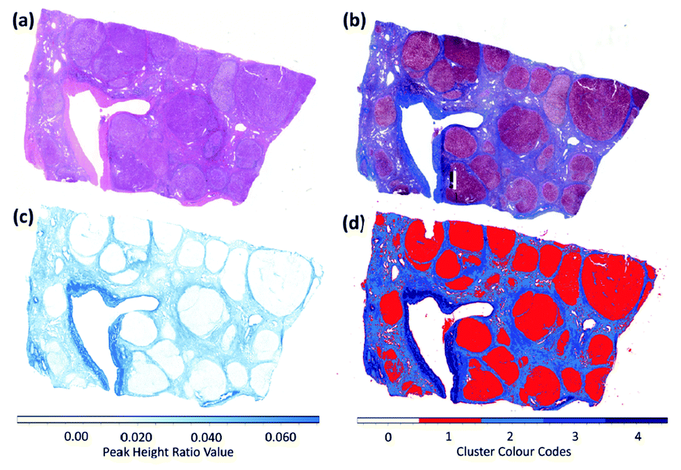 | ||
| Fig. 22 Mid-infrared based histochemical imaging of a large liver biopsy tissue section (1.8 cm × 1.2 cm in size). (a) Brightfield image of the parallel H&E stained tissue section examined by infrared microscopy. (b) Brightfield image of parallel tissue section stained using the Masson's trichrome protocol. (c) Peak height ratio image calculated using the band ratio (1232/1336 cm−1), mapped against a white-blue colour palette. (d) k-Means clustering image (4 clusters) calculated from band ratio values (1232/1336 cm−1) of a 4-frequency infrared absorbance dataset. Reproduced from ref. 102 with permission from the Royal Society of Chemistry. | ||
In another case study, Bird and Rowlette103 investigated colorectal tissue specimen using a QCL-based imaging infrared microscope. Both, sparse wavelengths datasets (10 wavelengths) and full band spectra (900–1800 cm−1) were recorded using a high NA objective (NA = 0.7). The instrument allowed for imaging with a field of view of 650 × 650 μm2 and a projected pixel size of 1.35 μm using an uncooled microbolometer array detector. The authors used the sparse wavelength datasets to calculate a protein map (peak height ration of amide I and amide II), a collagen map (peak height of collagen CH2 side chain vibration at 1360 cm−1) and a mucin map (mucin glycosylation band at 1044 cm−1), with additional wavelength recorded for baseline correction. Second derivatives of full band spectra of colorectal tissue were analyzed by k-means cluster analysis with 6 clusters.
While the authors show cluster mean spectra and state that “…artefacts caused by coherence were not observed as problematic…”103 it has to be noted that the impact of coherence may not be visible in mean spectra: when averaging over many pixels, mean spectra (such as cluster mean spectra) may or may not resemble the gold standard, i.e. FT-IR spectroscopy. However, the signals at any individual pixel will be impacted by the coherent diffraction of the laser radiation, which depends on the local phase of the radiation and, therefor, on local refractive indices, sample thicknesses, cell sizes, etc. as pointed out earlier by Kole et al.80 This impact of coherence constitutes a intrinsic property of QCLs and, hence, QCL-based imaging, if not further precautions are taken.82 The impact of coherence may be exemplified by the spectroscopy of a thin, homogenous film of photoresist on an IR-transparent slide: Fig. 23 shows the profound deviations between FT-IR spectra taken from three arbitrarily chosen spots of the homogenous film and the corresponding spectra from a high-coherence QCL setup. If, on the other hand, the time-average spatial coherence is reduced like in the QCL setup of e.g. Schönhals et al.,82 Kröger et al.,90 the spectra strongly resemble the FT-IR spectra. Note that the impact of coherence sometimes even prevails upon averaging over an area of e.g. 100 × 100 μm2 (see Fig. 23 (right)). While – if no precautions are taken – homogenous samples already show such devastating effect of coherence on the QCL-based microspectroscopy, the situation gets worse for structured samples like tissue thin sections as illustrated in Fig. 24 and as explained in detail in ref. 82.
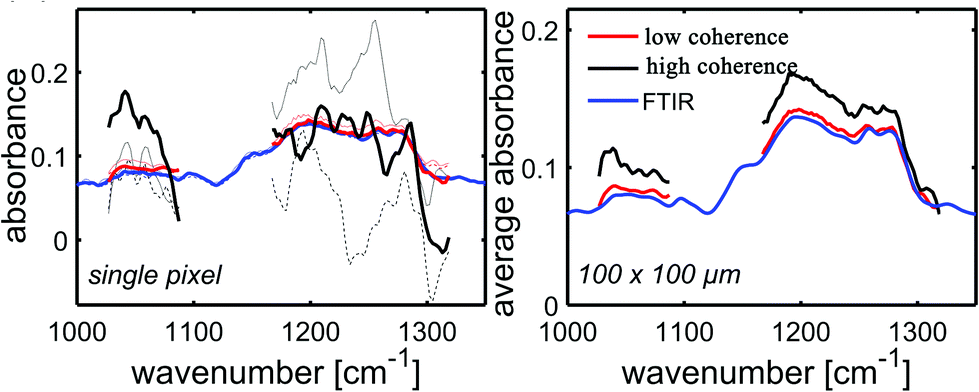 | ||
| Fig. 23 Spectra of a homogeneous thin layer of photoresist are sampled (left) on three random positions obtained with an FT-IR microscope, a high-coherence, QCL-based microscope and a QCL-based microscope with a hardware solution to reduce the time-averaged spatial coherence of the illumination.82 Profound discrepancies between the FT-IR and QCL (high coherence) spectra are evident, while differences between the FT-IR and the low-coherence QCL spectra are very small. (Right) This impact of coherence may even prevail if spectra are averaged over a 100 × 100 μm area of the homogenous photoresist. Reproduced with permissions of Schönhals et al.,82 John Wiley and Sons. | ||
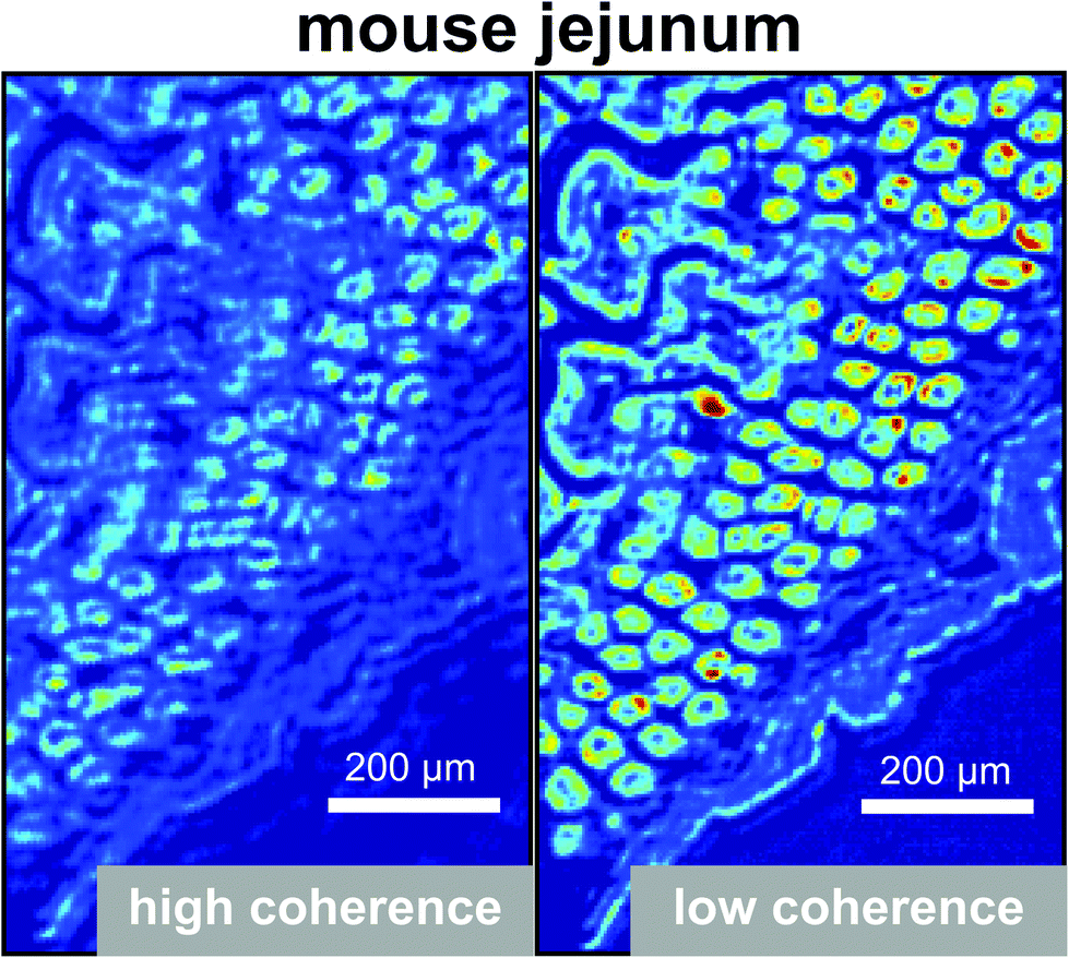 | ||
| Fig. 24 QCL-based absorbance images obtained from a tissue thin section of a mouse jejunum at a wavenumber of 1051 cm−1. High coherence (left): the QCL is directly used as an illumination source for QCL-based microspectroscopy and strong interference effects are evident, especially at the edges of the tissue (“edge ringing”). Low Coherence (right): the time-average spatial coherence is strongly reduced by means of appropriately placed and operated diffusors in the illumination beam pathsuch that the impact of coherence is strongly reduced. Reproduced with permissions of Schönhals et al.,82 John Wiley and Sons. | ||
Yeh et al.81 published information about their custom built QCL-based imaging infrared microscope, which combined the illumination originating from several multiplexed QCLs with a cooled MCT-FPA detector (field-of-view of 122 μm, projected pixel size of 0.95 μm). Careful synchronization of the illuminating QCLs with the MCT-FPA detector allowed for very fast hyperspectral imaging over the spectral region ranging from 777 to 1904 cm−1, as was demonstrated by acquiring hyperspectral data of a breast TMAs (see Fig. 25). By using deliberate integration and postprocessing techniques, the QCL-based setup was able to achieve a ∼(1100/N)-fold speedup for measuring N essential spectral features for tissue and enabled the acquisition of images with more than 50 megapixel in a convenient time frame.81
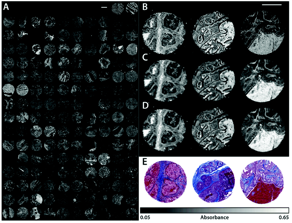 | ||
| Fig. 25 (A) Absorbance data of 148 tissue cores from the BRC1501 TMA acquired by the QCL microscope with the 0.56 NA (2.02 μm) objective. The net scan time of the fingerprint ranging from 776.9 to 1904.4 cm−1 at 4 cm−1 resolution was approximately 5 h. Only the amide I absorbance band at 1656 cm−1 from the full spectral data set is displayed. Selected tissue cores (C2, C7, G5) are also imaged by the (B) QCL with the 0.85 NA (0.95 μm) objective, (C) LA FT-IR (6.25 μm), and (D) FPA FT-IR (1.05 μm). (E) A brightfield image of a serial core section treated with Masson's trichrome stain as performed in traditional histological studies. The scale bars in all images represent 500 μm. Reprinted with permission from Yeh et al.81 Copyright (2015) American Chemical Society. | ||
The group also compared overall performance of their custom built, QCL-based infrared microscope to commercial FT-IR systems. While Yeh et al.81 conclude that the QCL-based systems seemingly offered better spatial resolving power that FT-IR systems and competitive signal-to-noise ratio, signals caused by the coherence of the QCL source have been found to be the limiting factor in terms of applicability of the QCL-based microscope for chemical imaging of cells and tissue in the absence of appropriate means to reduce the impact of coherence in agreement with earlier findings by Kole et al.80
In a recent study, Kuepper et al.104 confirmed earlier insights concerning the strong improvements in acquisition speed by means of QCL-based microspectroscopy90 and performed a feasibility study concerning the application to colorectal cancer. The authors hereby distinguish between instrumental artefacts of coherence and the sample-specific impact of coherence. The first issue of coherence was mitigated by improvements in the stability of QCLs, while the latter was partly accounted for by training a random forest classification algorithm specifically with respect to the spectral signals originating from coherence effects. In passing we would like to note that the locations of cell debris and blood have been sorted out, too. Using an independent data set for validation, the authors were able to correctly identify 78 of the 81 tissue thin sections and all of the 18 tissue thin sections, which were considered cancerous or non-cancerous by a histopathologist, respectively. Further investigations solidified the approach in that data was compared to FT-IR microspectroscopy as well as by using a second QCL-microscope of the same type. Despite the success in this specific application case with regards translating MIR spectroscopy to the clinical application, the authors also conclude that, “however, coherence effects on sample edges and the sample itself must be addressed in future studies to obtain not only tissue classification but also comparable spectral quality to FTIR”.104
In order to reduce the impact of coherence, Ran et al.105 developed an imaging modality which combines QCL illumination with an MCT detector array and a local translation of the sample: by moving the sample with respect to the laser beam and detector array, the authors are able illustrate a reduction of fringing by more than a factor of 3. Next to an increased numerical aperture the authors believe that the reduction of fringing is achieved by means of the incoherent integration of signals in the direction of motion. The method was applied to SU-8 USAF target on a BaF2 substrate as well as on breast tissue thin sections.
The spatial resolution of all of the microscopes mentioned above is limited by Abbe's diffraction limit (for a recent discussion on spatial resolution versus pixel resolution in MIR microscopy see ref. 106, 107). However, this limitation does not apply to the near field and QCLs are particularly suited to be combined with scattering-type scanning near field optical microscopes and Atomic Force Microscope-Infrared spectroscopy (AFM-IR).108 In a recent study, Kenkel et al.109 reported the investigation of, for example, mammary epithelial cells. The authors implemented an online correction of the changes of the responsivity caused by probe-sample interaction to isolate information about sample expansion. By adding a piezo actuator to the sample mount, they were able to induce out-of-plan sample motions to measure responsivity variations of the cantilever caused by changes in local sample mechanical properties and correct responsivity for these changes. In a one-to-one comparison between the standard resonance tracking technique and the newly proposed responsivity correction, the authors demonstrated the profound increase in acquisition speed as well as sensitivity, accuracy, and repeatability with their newly developed technique, while also maintaining the sub-diffraction limited nanoscale resolution of standard AFM-IR setups.
6. Conclusion
The advances in the field of mid-infrared laser technology, especially the availability of quantum cascade lasers from various sources, have opened up a new window to biology and medicine. Hereby, QCL-based methods have benefited from the many years of intense research in FT-IR spectroscopy but now are mitigating or even avoiding some of the shortcomings of this traditional approach. Right now, QCL-based spectroscopy and microspectroscopy appear to be on the verge of speeding the translation of mid-infrared spectroscopy into day-to-day biomedical applications.Conflicts of interest
The authors are inventors of various patents and/or patent applications in the field. While this review was written as part of their affiliation with Heidelberg University, N.K. is an employee of Bruker Optik GmbH and W.P. is an employee of Roche Diabetes Care GmbH.References
- Infrared Spectroscopy: New Tool in Medicine, ed. H. Mantsch and M. Jackson, SPIE Society of Photo-Optical Instrumentation Engineering, 1998, vol. 3257 Search PubMed.
- W. Petrich, Appl. Spectrosc. Rev., 2001, 36, 181–237 CrossRef CAS.
- D. Naumann, Appl. Spectrosc. Rev., 2001, 36, 239–298 CrossRef CAS.
- T. A. Keiderling, J. Kubelka and J. Hilario, Vibrational Spectroscopy of Biological and Polymeric Materials, CRC Press, Boca Raton, 2006, pp. 253–324 Search PubMed.
- D. Naumann, H. Fabian and P. Lasch, Biological and Biomedical Infrared Spectroscopy, IOS Press, Amsterdam, The Netherlands, 2009, pp. 312–354 Search PubMed.
- Encyclopedia of Spectroscopy and Spectrometry, ed. J. Lindon, G. E. Tranter and D. Koppenaal, Academic Press, 3rd edn, 2017 Search PubMed.
- L. Breiman, J. H. Friedman, R. A. Olshen and C. J. Stone, Classification and Regression Trees, Chapman & Hall, CRC, Taylor & Francis Group, 1984 Search PubMed.
- H. Martens and T. Naes, Multivariate Calibration, John Wiley & Sons Ltd., 1989 Search PubMed.
- C. M. Bishop, Pattern Recognition and Machine Learning, Springer Science & Business Media, LLC, 2006 Search PubMed.
- Biomedical Vibrational Spectroscopy, ed. P. Lasch and J. Kneipp, John Wiley & Sons, Inc., 2008 Search PubMed.
- M. S. Vitiello, G. Scalari, B. Williams and P. D. Natale, Opt. Express, 2015, 23, 5167–5182 CrossRef CAS PubMed.
- J. Faist, F. Capasso, D. L. Sivco, C. Sirtori, A. L. Hutchinson and A. Y. Cho, Science, 1994, 264, 553–556 CrossRef CAS PubMed.
- J. Faist, Quantum Cascade Lasers, OUP, Oxford, 2013 Search PubMed.
- V. M. Zolotarev, B. A. Mikhilov, L. L. Alperovich and S. I. Popov, Opt. Spectrosc., 1969, 27, 430–432 Search PubMed.
- W. M. Irvine and J. B. Pollack, Icarus, 1968, 8, 324–360 CrossRef CAS.
- G. M. Hale and M. R. Querry, Appl. Opt., 1973, 12, 555–563 CrossRef CAS PubMed.
- S. Y. Venyaminov and F. G. Prendergast, Anal. Biochem., 1997, 248, 234–245 CrossRef CAS PubMed.
- P. Lasch, J. Schmitt, M. Beekes, T. Udelhoven, M. Eiden, H. Fabian, W. Petrich and D. Naumann, Anal. Chem., 2003, 75, 6673–6678 CrossRef CAS PubMed.
- D. R. Rohleder, G. Kocherscheidt, K. Gerber, W. Kiefer, W. Köhler, J. Möcks and W. Petrich, J. Biomed. Opt., 2005, 10, 031108 CrossRef CAS PubMed.
- W. Petrich, B. Dolenko, J. Früh, M. Ganz, H. Greger, S. Jacob, F. Keller, A. E. Nikulin, M. Otto, O. Quarder, R. L. Somorjai, A. Staib, G. Werner and H. Wielinger, Appl. Opt., 2000, 39, 3372–3379 CrossRef CAS PubMed.
- W. Zhou, N. Bandyopadhyay, D. Wu, R. McClintock and M. Razeghi, Sci. Rep., 2016, 6, 25213 CrossRef CAS PubMed.
- W. Cao and Y. Duan, Clin. Chem., 2006, 52, 800–811 CrossRef CAS PubMed.
- K. Wörle, F. Seichter, A. Wilk, C. Armacost, T. Day, M. Godejohann, U. Wachter, J. Vogt, P. Radermacher and B. Mizaikoff, Anal. Chem., 2013, 85, 2697–2702 CrossRef PubMed.
- J. H. Shorter, D. D. Nelson, J. B. McManus, M. S. Zahniser and D. K. Milton, IEEE Sens. J., 2010, 10, 76–84 CAS.
- D. Marchenko, J. Mandon, S. M. Cristescu, P. J. F. M. Merkus and F. J. M. Harren, Appl. Phys. B, 2013, 111, 359–365 CrossRef CAS.
- T. Katagiri, K. Shibayama, T. Iida and Y. Matsuura, Sensors, 2018, 18, 995 CrossRef PubMed.
- Y. Wang, M. Nikodem, E. Zhang, F. Cikach, J. Barnes, S. Comhair, R. A. Dweik and C. Kao, Sci. Rep., 2015, 5, 9096 CrossRef PubMed.
- Y. Ma, R. Lewicki, M. Razeghi and F. Tittel, Opt. Express, 2013, 21, 1008–1019 CrossRef CAS PubMed.
- Z. Wang and C. Wang, J. Breath Res., 2013, 7, 037109 CrossRef PubMed.
- A. Reyes-Reyes, R. C. Horsten, H. P. Urbach and N. Bhattacharya, Anal. Chem., 2015, 87, 507–512 CrossRef CAS PubMed.
- R. Centeno, J. Mandon, F. J. M. Harren and S. M. Cristescu, Photonics, 2016, 3, 22 CrossRef.
- K. Owen and A. Farooq, Appl. Phys. B, 2014, 116, 371–383 CrossRef CAS.
- J. Manne, O. Sukhorukov, W. Jäger and J. Tulip, Appl. Opt., 2006, 45, 9230–9237 CrossRef PubMed.
- Y. A. Bakhirkin, A. A. Kosterev, G. Wysocki, F. K. Tittel, T. H. Risby and J. D. Bruno, Laser Applications to Chemical, Security and Environmental Analysis, 2008, p. LMB4 Search PubMed.
- R. Lewicki, A. A. Kosterev, D. M. Thomazy, T. Risby, S. Solga, T. B. Schwartz and F. Tittel, Proc. SPIE, 2011, 7945, 79450K1-7 CrossRef.
- J. Manne, W. Jäger and J. Tulip, Appl. Phys. B, 2008, 94, 337 CrossRef.
- G. Wysocki, R. Curl, F. Tittel, R. Maulini, J. Bulliard and J. Faist, Appl. Phys. B, 2005, 81, 769–777 CrossRef CAS.
- J. Myers, D. Walsh, M. Sullivan and V. Froelicher, J. Appl. Physiol., 1990, 68, 404–410 CrossRef CAS PubMed.
- B. Thekedar, W. Szymczak, V. Höllriegl, C. Hoeschen and U. Oeh, J. Breath Res., 2009, 3, 027007 CrossRef CAS PubMed.
- D. Smith, P. Španel, A. A. Fryer, F. Hanna and G. A. A. Ferns, J. Breath Res., 2011, 5, 022001 CrossRef PubMed.
- P. Španel, K. Dryahina, A. Rejšková, T. W. E. Chippendale and D. Smith, Physiol. Meas., 2011, 32, N23 CrossRef PubMed.
- O. Lawal, W. M. Ahmed, T. M. E. Nijsen, R. Goodacre and S. J. Fowler, Metabolomics, 2017, 13, 110 CrossRef PubMed.
- F. Siebert and P. Hildebrandt, Vibrational Spectroscopy in Life Science, Wiley-VCH Verlag GmbH & Co. KGaA, 2008 Search PubMed.
- B. Lendl, J. Frank, R. Schindler, A. Müller, M. Beck and J. Faist, Anal. Chem., 2000, 72, 1645–1648 CrossRef CAS PubMed.
- W. B. Martin, S. Mirov and R. Venugopalan, Appl. Spectrosc., 2005, 59, 881–884 CrossRef CAS PubMed.
- A. Lambrecht, T. Beyer, K. Hebestreit, R. Mischler and W. Petrich, Appl. Spectrosc., 2006, 60, 729–736 CrossRef CAS PubMed.
- M. Diem, J. Biophotonics, 2018, 11, e201800064 CrossRef PubMed.
- C. Vrančić, A. Fomichova, N. Gretz, C. Herrmann, S. Hoecker, A. Pucci and W. Petrich, Analyst, 2011, 136, 1192–1198 RSC.
- C. Vrančić, N. Kröger, N. Gretz, S. Neudecker, A. Pucci and W. Petrich, Anal. Chem., 2014, 86, 10511–10514 CrossRef PubMed.
- S. Schaden, A. Domínguez-Vidal and B. Lendl, Appl. Phys. B, 2006, 83, 135–139 CrossRef CAS.
- K. Haase, N. Müller and W. Petrich, Proc. SPIE, 2018, 10490, 10490 Search PubMed.
- M. Brandstetter, A. Genner, K. Anic and B. Lendl, Analyst, 2010, 135, 3260–3265 RSC.
- M. R. Alcaráz, A. Schwaighofer, C. Kristament, G. Ramer, M. Brandstetter, H. Goicoechea and B. Lendl, Anal. Chem., 2015, 87, 6980–6987 CrossRef PubMed.
- J. Kuligowski, G. Quintás and B. Lendl, Appl. Phys. B, 2010, 99, 833–840 CrossRef CAS.
- M. Brandstetter, T. Sumalowitsch, A. Genner, A. E. Posch, C. Herwig, A. Drolz, V. Fuhrmann, T. Perkmann and B. Lendl, Analyst, 2013, 138, 4022–4028 RSC.
- A. Schwaighofer, M. R. Alcaráz, C. Araman, H. Goicoechea and B. Lendl, Sci. Rep., 2016, 6, 33556 CrossRef CAS PubMed.
- A. Lambrecht, M. Pfeifer, W. Konz, J. Herbst and F. Axtmann, Analyst, 2014, 139, 2070–2078 RSC.
- J. Kuligowski, A. Schwaighofer, M. R. Alcaráz, G. Quintás, H. Mayer, M. Vento and B. Lendl, Anal. Chim. Acta, 2017, 963, 99–105 CrossRef CAS PubMed.
- A. Schwaighofer, J. Kuligowski, G. Quintás, H. K. Mayer and B. Lendl, Food Chem., 2018, 252, 22–27 CrossRef CAS PubMed.
- M. R. Alcaráz, A. Schwaighofer, H. Goicoechea and B. Lendl, Anal. Bioanal. Chem., 2016, 408, 3933–3941 CrossRef PubMed.
- T. F. Beskers, M. Brandstetter, J. Kuligowski, G. Quintás, M. Wilhelm and B. Lendl, Analyst, 2014, 139, 2057–2064 RSC.
- A. Edelmann, C. Ruzicka, J. Frank, B. Lendl, W. Schrenk, E. Gornik and G. Strasser, J. Chromatogr., A, 2001, 934, 123–128 CrossRef CAS PubMed.
- M. Brandstetter, L. Volgger, A. Genner, C. Jungbauer and B. Lendl, Appl. Phys. B, 2013, 110, 233–239 CrossRef CAS.
- M. Grafen, S. Delbeck, H. Busch, H. M. Heise and A. Ostendorf, Proc. SPIE, 2018, 10501, 10501 Search PubMed.
- S. Liakat, K. A. Bors, T.-Y. Huang, A. P. M. Michel, E. Zanghi and C. F. Gmachl, Biomed. Opt. Express, 2013, 4, 1083–1090 CrossRef CAS PubMed.
- S. Lüdeke, M. Pfeifer and P. Fischer, J. Am. Chem. Soc., 2011, 133, 5704–5707 CrossRef PubMed.
- V. Cimalla, S. Hugger, F. Fuchs, J. Anzt, M. Bitterling, N. Yang, C. Kohl, T. Maucher, I. Mühlemeier, A. Burger-Kentischer and I. Trick, Procedia Eng., 2015, 120, 975–978 CrossRef CAS.
- Y.-C. Chang, P. Wagli, V. Paeder, A. Homsy, L. Hvozdara, P. van der Wal, J. Di Francesco, N. F. de Rooij and H. Peter Herzig, Lab Chip, 2012, 12, 3020–3023 RSC.
- P. Wägli, Y.-C. Chang, A. Homsy, L. Hvozdara, H. P. Herzig and N. F. de Rooij, Anal. Chem., 2013, 85, 7558–7565 CrossRef PubMed.
- P. Jouy, M. Mangold, B. Tuzson, L. Emmenegger, Y.-C. Chang, L. Hvozdara, H. P. Herzig, P. Wagli, A. Homsy, N. F. de Rooij, A. Wirthmueller, D. Hofstetter, H. Looser and J. Faist, Analyst, 2014, 139, 2039–2046 RSC.
- A. Schönhals, H. Tholl, M. Glasmacher, N. Kröger-Lui, A. Pucci and W. Petrich, Analyst, 2017, 142, 1235–1243 RSC.
- S. Liakat, K. A. Bors, L. Xu, C. M. Woods, J. Doyle and C. F. Gmachl, Biomed. Opt. Express, 2014, 5, 2397–2404 CrossRef PubMed.
- J. Kottmann, J. M. Rey, J. Luginbühl, E. Reichmann and M. W. Sigrist, Biomed. Opt. Express, 2012, 3, 667–680 CrossRef CAS PubMed.
- M. A. Pleitez, T. Lieblein, A. Bauer, O. Hertzberg, H. von Lilienfeld-Toal and W. Mäntele, Rev. Sci. Instrum., 2013, 84, 084901 CrossRef PubMed.
- M. A. Pleitez, O. Hertzberg, A. Bauer, M. Seeger, T. Lieblein, H. V. Lilienfeld-Toal and W. Mäntele, Analyst, 2015, 140, 483–488 RSC.
- O. Hertzberg, A. Bauer, A. Kuderle, M. A. Pleitez and W. Mäntele, Analyst, 2017, 142, 495–502 RSC.
- E. Levenson, P. Lerch and M. C. Martin, Infrared Phys. Technol., 2006, 49, 45–52 CrossRef CAS.
- S. Tiwari, J. Raman, V. Reddy, A. Ghetler, R. P. Tella, Y. Han, C. R. Moon, C. D. Hoke and R. Bhargava, Anal. Chem., 2016, 88, 10183–10190 CrossRef CAS PubMed.
- T. P. Wrobel, P. Mukherjee and R. Bhargava, Analyst, 2017, 142, 75–79 RSC.
- M. R. Kole, R. K. Reddy, M. V. Schulmerich, M. K. Gelber and R. Bhargava, Anal. Chem., 2012, 84, 10366–10372 CrossRef CAS PubMed.
- K. Yeh, S. Kenkel, J.-N. Liu and R. Bhargava, Anal. Chem., 2015, 87, 485–493 CrossRef CAS PubMed.
- A. Schönhals, N. Kröger-Lui, A. Pucci and W. Petrich, J. Biophotonics, 2018, 11, e201800015 CrossRef PubMed.
- S. Mittal, K. Yeh, L. S. Leslie, S. Kenkel, A. Kajdacsy-Balla and R. Bhargava, Proc. Natl. Acad. Sci. U. S. A., 2018, 1–10 Search PubMed.
- F. Niklaus, C. Vieider and H. Jakobsen, Proc. SPIE, 2008, 6836, 6836 Search PubMed.
- M. C. Phillips and N. Hô, Opt. Express, 2008, 16, 1836–1845 CrossRef CAS PubMed.
- M. C. Phillips and B. E. Bernacki, Opt. Eng., 2013, 52, 52 Search PubMed.
- C. Hughes, G. Clemens, B. Bird, T. Dawson, K. M. Ashton, M. D. Jenkinson, A. Brodbelt, M. Weida, E. Fotheringham, M. Barre, J. Rowlette and M. J. Baker, Sci. Rep., 2016, 6, 20173 CrossRef CAS PubMed.
- A. Staib, B. Dolenko, D. Fink, J. Früh, A. Nikulin, M. Otto, M. Pessin-Minsley, O. Quarder, R. Somorjai, U. Thienel, G. Werner and W. Petrich, Clin. Chim. Acta, 2001, 308, 79–89 CrossRef CAS.
- W. Petrich, K. B. Lewandrowski, J. B. Muhlestein, M. E. H. Hammond, J. L. Januzzi, E. L. Lewandrowski, R. R. Pearson, B. Dolenko, J. Früh, M. Haass, M. M. Hirschl, W. Köhler, R. Mischler, J. Möcks, J. Ordóñez-Llanos, O. Quarder, R. Somorjai, A. Staib, C. Sylvén, G. Werner and R. Zerback, Analyst, 2009, 134, 1092–1098 RSC.
- N. Kröger, A. Egl, M. Engel, N. Gretz, K. Haase, I. Herpich, B. Kränzlin, S. Neudecker, A. Pucci, A. Schönhals, J. Vogt and W. Petrich, J. Biomed. Opt., 2014, 19, 19 CrossRef PubMed.
- N. Kröger, A. Egl, M. Engel, N. Gretz, K. Haase, I. Herpich, S. Neudecker, A. Pucci, A. Schönhals and W. Petrich, Proc. SPIE, 2014, 8939, 8939 Search PubMed.
- N. Kröger-Lui, N. Gretz, K. Haase, B. Kränzlin, S. Neudecker, A. Pucci, A. Regenscheit, A. Schönhals and W. Petrich, Analyst, 2015, 140, 2086–2092 RSC.
- A. Hasenkampf, N. Kröger, A. Schönhals, W. Petrich and A. Pucci, Opt. Express, 2015, 23, 5670–5680 CrossRef CAS PubMed.
- K. Haase, N. Kröger-Lui, A. Pucci, A. Schönhals and W. Petrich, Faraday Discuss., 2016, 187, 119–134 RSC.
- K. Haase, N. Kröger-Lui, A. Pucci, A. Schönhals and W. Petrich, J. Biophotonics, 2016, 9, 61–66 CrossRef CAS PubMed.
- P. Bassan, M. J. Weida, J. Rowlette and P. Gardner, Analyst, 2014, 139, 3856–3859 RSC.
- H. Sreedhar, V. K. Varma, F. V. Gambacorta, G. Guzman and M. J. Walsh, Biomed. Opt. Express, 2016, 7, 2419–2424 CrossRef CAS PubMed.
- M. J. Pilling, A. Henderson, B. Bird, M. D. Brown, N. W. Clarke and P. Gardner, Faraday Discuss., 2016, 187, 135–154 RSC.
- B. H. Menze, B. M. Kelm, R. Masuch, U. Himmelreich, P. Bachert, W. Petrich and F. A. Hamprecht, BMC Bioinf., 2009, 10, 213 CrossRef PubMed.
- J. A. Swets, Signal detection theory and ROC analysis in psychology and diagnostics: Collected papers, Psychology Press, 2014 Search PubMed.
- M. J. Pilling, A. Henderson and P. Gardner, Anal. Chem., 2017, 89, 7348–7355 CrossRef CAS PubMed.
- B. Bird and J. Rowlette, Analyst, 2017, 142, 1179–1184 RSC.
- B. Bird and J. Rowlette, Analyst, 2017, 142, 1381–1386 RSC.
- C. Kuepper, A. Kallenbach-Thieltges, H. Juette, A. Tannapfel, F. Großerueschkamp and K. Gerwert, Sci. Rep., 2018, 8, 7717 CrossRef PubMed.
- S. Ran, S. Berisha, R. Mankar, W.-C. Shih and D. Mayerich, Biomed. Opt. Express, 2018, 9, 832–843 CrossRef PubMed.
- W. Petrich, Faraday Discuss., 2016, 187, 603–607 RSC.
- T. Wrobel and R. Bhargava, Anal. Chem., 2018, 90, 1444–1463 CrossRef CAS PubMed.
- I. Amenabar, S. Poly, W. Nuansing, A. A. Hubrich, E. H. Govyadinov, F. Huth, R. Krutokhvostov, L. Zhang, M. Knez, J. Heberle, A. M. Bittner and R. Hillenbrand, Nat. Commun., 2013, 4, 2890 CrossRef PubMed.
- S. Kenkel, A. Mittal, S. Mittal and R. Bhargava, Anal. Chem., 2018, 90, 8845–8855 CrossRef CAS PubMed.
Footnote |
| † Present address: Bruker Optik GmbH, Rudolf-Plank-Straße 27, 76275 Ettlingen, Germany. |
| This journal is © The Royal Society of Chemistry 2018 |