
 Open Access Article
 This Open Access Article is licensed under a
 Creative Commons Attribution 3.0 Unported Licence
Concentrating and labeling genomic DNA in a nanofluidic array†
Rodolphe
Marie
 *a,
Jonas N.
Pedersen
a,
Kalim U.
Mir
b,
Brian
Bilenberg
c and
Anders
Kristensen
a
*a,
Jonas N.
Pedersen
a,
Kalim U.
Mir
b,
Brian
Bilenberg
c and
Anders
Kristensen
a
aDepartment of Micro and Nanotechnology, Technical University of Denmark, Kongens Lyngby, Denmark. E-mail: rcwm@nanotech.dtu.dk; Fax: +45 4588 7762; Tel: +45 4525 5700
bXGenomes, Pagliuca Harvard Life Lab, 127 Western Ave, Boston, USA
cNIL Technology ApS., Kongens Lyngby, Denmark
First published on 4th January 2018
Abstract
Nucleotide incorporation by DNA polymerase forms the basis of DNA sequencing-by-synthesis. In current platforms, either the single-stranded DNA or the enzyme is immobilized on a solid surface to locate the incorporation of individual nucleotides in space and/or time. Solid-phase reactions may, however, hinder the polymerase activity. We demonstrate a device and a protocol for the enzymatic labeling of genomic DNA arranged in a dense array of single molecules without attaching the enzyme or the DNA to a surface. DNA molecules accumulate in a dense array of pits embedded within a nanoslit due to entropic trapping. We then perform ϕ29 polymerase extension from single-strand nicks created on the trapped molecules to incorporate fluorescent nucleotides into the DNA. The array of entropic traps can be loaded with λ-DNA molecules to more than 90% of capacity at a flow rate of 10 pL min−1. The final concentration can reach up to 100 μg mL−1, and the DNA is eluted from the array by increasing the flow rate. The device may be an important preparative module for carrying out enzymatic processing on DNA extracted from single-cells in a microfluidic chip.
1. Introduction
Current DNA sequencing methods require the DNA to be purified from other cell components and be processed enzymatically for library preparation. For example, sequencing-by-synthesis using reversible terminators, which is the most widespread next-generation sequencing method,1 relies on the activity of DNA polymerase on a template DNA annealed to primers immobilized on a planar solid support. Another commercial method performs real-time sequencing-by-synthesis on template DNA captured by polymerase immobilized in nanovials.2Microfluidics as a method to extract nucleic acids from individual confined cells has given non-specialist researchers the ability to routinely prepare samples for single-cell sequencing using commercial products.3,4 Since purification and library preparation is a pre-requisite for current sequencing technologies, on-chip purification and enzymatic processing of DNA in confinement will be of great importance for the evolution of single cell nucleic acid analysis methods. Possible techniques for DNA purification in a micron-scale device are field flow fractionation,5,6 dielectrophoresis,7 pillar arrays,8 and optical trapping.9 For most of these techniques, DNA is retrieved before further use. However, entropic trapping, which relies on the differences in free energies of DNA trapped in different volumes, offers the potential for performing DNA purification and further processing within an integrated device.
In previous reports, grooves in a slit formed the entropic traps.10,11 This design was first used for the separation of DNA according to length12 or topology13 under a constant flow. When the flow was stopped, DNA molecules settled in the grooves to minimize their free energy. The final conformation of the molecules depended on their lengths and the groove dimensions. Entropic trapping of genomic DNA has some desirable properties: it does not require external fields, flows, or attachment to a surface. DNA is still accessible to diffusing reagents such as enzymes, and the DNA molecules can be released from the traps by manipulating the buffer flow.
Enzymatic reactions in confinement is the key to emerging single-molecule technologies for bio-analysis.14 It is now possible to use nano-confinement to obtain genomic information from single DNA molecules from the mega base-pair (Mb) range,15 through the kilo base-pair (kb) range.16–19 Enzymatic reactions on freely moving genomic DNA in nanochannels was first demonstrated by Riehn et al.20 Later, Persson et al. demonstrated the enzymatic digestion of DNA immobilized in entropic traps.21
Here, we show that DNA molecules can be concentrated and enzymatically processed in an array of nanopits within which individual DNA molecules are isolated and imaged. Because the molecules are not physically attached to a surface within the nanopit they can be easily liberated for further processing in bulk downstream.
2. Experimentals
2.1. Device design
Microchannels connect the inlets to the nanoslit, and a nanoslit (light grey region) connects the left and right microchannels (Fig. 1). The nanoslit branches out into eight parallel 20 μm wide arms just before the right microchannel. The width of the slit is at most 20 μm in order to avoid a collapse of the lid. The eight arms near the right microchannel contain arrays of square nanopits. Side lengths of the pits are 600, 800 or 1000 nm, and the pits are 200 nm deep. Nanopits are arranged on a 40 × 10 square lattice with a 2 μm pitch in both directions. An applied pressure drop forces liquid to flow from the left to the right microchannel. The branching of the nanoslit provides a 32-fold reduction in flow velocity between the entrance of the slit and the nanopit arrays. The reduction in flow velocity enables DNA accumulation in the nanopit arrays.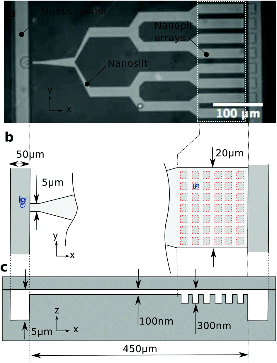 | ||
| Fig. 1 Device design and dimensions. (a) Bright-field image of the polymer chip with a branched slit connecting two microchannels. (b) Schematics of the slit entrance and the nanopit array. The slit is 5 μm wide at the entrance and 20 μm wide over the nanopit arrays. Due to the branched design of the slit, there is a 32-fold drop in flow velocity between the entrance and the pit area. (c) Side view of the structure showing the various depths in the device. | ||
2.2. Device fabrication
The device is fabricated by injection moulding of a cyclic olefin copolymer (COC) with a Ni master as described elsewhere.22 There are three different depths in our device. First, an array of pits is defined at a 300 nm depth by e-beam lithography and reactive ion etching in a silicon substrate, then a nanoslit defined by UV-lithography and etched at a 100 nm depth, and, finally, microchannels defined by UV-lithography and etched at a depth of 5 μm. The Ni master is replicated in COC (TOPAS 5013) by injection moulding. The injection moulded part with the fluidic structure is sealed with a 150 μm thick COC foil by UV-assisted thermal bonding.2.3. DNA array loading
λ-Phage DNA (Wako, Japan) is stained with YOYO-1 (Invitrogen) at a 5![[thin space (1/6-em)]](https://www.rsc.org/images/entities/char_2009.gif) :1 staining ratio. Staining increases the persistence length of double-stranded DNA to 64 nm and the contour length of λ-phage DNA to 21 μm. DNA is diluted to 1 μg mL−1 in a buffer consisting of 0.5× Tris-Borate-EDTA (TBE) + 1%v/v beta-mercaptoethanol (BME) + 0.5%v/v Triton-X100 to suppress photo-nicking and stiction to the polymer surface.
:1 staining ratio. Staining increases the persistence length of double-stranded DNA to 64 nm and the contour length of λ-phage DNA to 21 μm. DNA is diluted to 1 μg mL−1 in a buffer consisting of 0.5× Tris-Borate-EDTA (TBE) + 1%v/v beta-mercaptoethanol (BME) + 0.5%v/v Triton-X100 to suppress photo-nicking and stiction to the polymer surface.
2.4. Enzymatic assay
To perform the enzymatic reaction, the device is coated before the DNA sample is introduced by a 1 mM solution of phospholipids (1-palmitoyl-2-oleoyl-sn-glycero-3-phosphocholine (POPC, Avanti Lipids) and 1-palmitoyl-2-oleoyl-sn-glycero-3-phosphoglycerol (POPG, Avanti Lipids)) at a ratio of 3:1 in 5% ethanol. DNA is diluted to 1 μg mL−1 in a buffer consisting of 0.5× TBE + 1% BME and loaded into the array. The polymerase reaction is performed under a moderate flow of less than 1 μm s−1 above the array of pits with a reagent mix (polymerase ϕ29 1 unit, 20 μM of dATP, dGTP, dTTP, 10 μM of dCTP and 25 μM of Cy3-dCTP in 1× reaction buffer) for 2 hours at 30 °C. DNA is washed by flowing 0.5× TBE + 1% BME in the nanoslit before recording the YOYO-1 and Cy3 signals from four arrays of nanopit. Fig. 2 and 3 show only one of these four arrays.
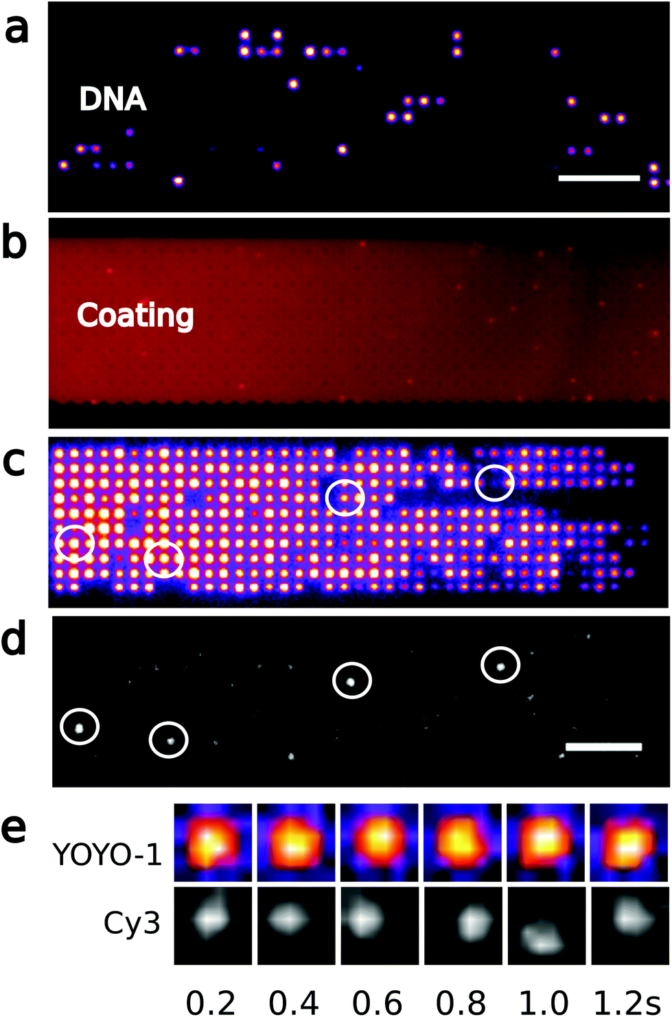 | ||
| Fig. 2 Polymerase reaction on arrayed genomic DNA. (a) Fluorescence image of YOYO-1 labeled λ-DNA diluted in a 40 × 10 array of 1000 nm square pits, and (b) the phospholipid coating. Scale bar is 10 μm. (c) YOYO-1 signal from λ-DNA molecules concentrated in an array of pits, and (d) Cy3 signal after incorporation of dCTP-Cy3 by ϕ29 polymerase. Circles indicate examples of pits where both YOYO-1 and Cy3 signals are detected. Scale bar is 10 μm. (e) Time-lapse of YOYO-1 and Cy3 signal from a molecule in a single pit. The YOYO-1 signal spans the whole pit, while the maximum of the Cy-3 signal moves around in the pit. | ||
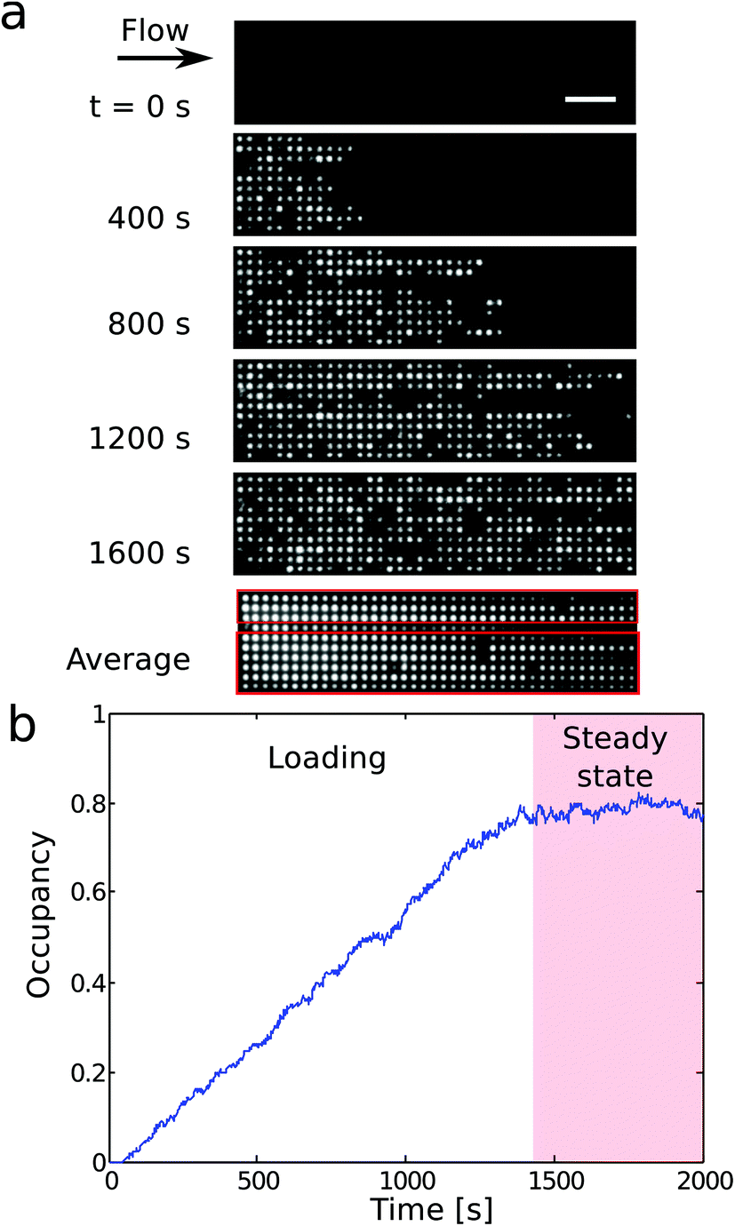 | ||
| Fig. 3 (a) Time lapse fluorescence imaging of DNA accumulating in a 1000 nm pit array under constant flow. A time average over the whole experiment reveals that a defect in the first column of pits reduces the total number of accessible pits to the DNA to 360 (red boxes). (b) Fractional occupancy versus time for a 1000 nm pit array for a pressure drop ΔP = 0.3 bar. | ||
2.5. Data analysis
We record the YOYO-1 and the Cy3 signal in each pit (ESI Fig. 1a and b†), but also the local background (green squares in ESI Fig. 1a and b†). ESI Fig. 1c and d† show the distribution of YOYO-1 and Cy3 intensities. From the YOYO-1 signal and a fixed threshold value (red, dashed line in ESI Fig. 1c†), we decide whether a DNA molecule occupies a pit or not. We define that an enzymatic reaction have occurred in a pit if (i) the pit is occupied by a DNA molecule, (ii) the Cy3 signal is above a threshold value (red, dashed line in ESI Fig. 1d†), and (iii) the Cy3 signal is not static, but moves around in the whole pit (see Fig. 2e). The latter criterion is to exclude Cy3-molecules bound to surfaces.3. Results and discussion
3.1. Concentrate single DNA molecules
We trap genomic DNA molecules to achieve both purification and labeling by a polymerase. Genomic DNA is accumulated in a dense array of entropic traps in a nanoslit (Fig. 1). The traps are square wells (nanopits) in a shallow channel (nanoslit).23 DNA molecules are introduced to the nanoslit by electrophoresis or a pressure driven flow and then settle in unoccupied pits to maximize their entropy. By modulating the flow velocity over the array,23 DNA is concentrated in the nanopit array across which they form a dense array of single molecules (Fig. 2c). We label λ-DNA trapped in pits by incorporating Cy3-labeled nucleotides directly into the double-strand using the strand displacement activity of polymerase ϕ29 from single stranded nicks (Fig. 2d). Demonstrating DNA synthesis by ϕ29 is a model reaction for sequencing-by-synthesis24 or sequence barcoding.25In previously reported devices,10,11,23 the field driving the DNA through the entropy landscape is constant, but the force required to push the DNA from the microchannel into the slit is also sufficient to make it escape the entropic traps. Here instead, DNA is accumulated in the traps by modulating the field driving the DNA over the trap array. In our design (Fig. 1), the nanoslit is narrower at its entry than over the pit arrays. This reduces the flow velocity over the pit arrays relative to the entrance from the microchannel (Fig. 1b). As a result, DNA accumulates in the pit arrays even under a constant flow (Fig. 3a and b). The distance between centers of neighboring pits is 2 μm, i.e., larger than the diffraction limit. So individual YOYO-1 labeled DNA molecules in pits can be imaged by epi-fluorescence microscopy (Fig. 2a and c). We only use DNA molecules of identical lengths (λ-DNA, 48 kb), so we can detect if a single molecule span several pits or a pit is double-occupied.
3.2. Enzymatic reaction in a nanofluidic array
Enzymatic reactions in confinement are challenging because of nonspecific interactions with surfaces. In previous work, silicon or glass devices were used that provided effective electrostatic repulsion of the DNA with the device surfaces.26 When proteins are used together with DNA,20,27–29 surfaces can be passivated by, e.g., BSA, or by forming a supported lipid bilayer21 that repels both DNA and proteins. However, single use lab-on-a-chip devices are preferably made of thermo-formable polymers that allow scalable production by industrial processes so that the fabrication cost is reduced.30 Here we thus use injection moulding to fabricate our device.22 The final device includes fluidic connectors and is suitable for single molecule imaging with high-NA optics.30 The stiction of DNA on COC can be effectively reduced by adding 0.5% Triton-X100 to the buffer, but as we here work with both DNA and polymerase enzymes, we coat the device surface with phospholipids. On COC, phospholipids form a smooth continuous layer on the polymer surface as revealed by labeling the phospholipids with Rhodamine B in a separate experiment (Fig. 2b).Nicks in DNA may occur accidentally during handling, imaging, mechanical shearing, or by photo-nicking. Fig. 2c shows YOYO-1 labeled genomic DNA arranged in 1000 × 1000 × 200 (nm)3 pits. Then we introduce a reaction buffer with ϕ29 polymerase, magnesium, ATP, and the four different nucleotides. One of the nucleotides is labeled with the fluorophore Cy3, and the ϕ29 polymerase fluorescently labels single-strand nicks. After the enzymatic reaction, excess nucleotides can effectively be washed away, and we observe Cy3 fluorescence from the nucleotides incorporated on the genomic DNA (Fig. 2d). The Cy3-labeled DNA molecules are distributed randomly in the array, indicating that reagents are successfully introduced over the entire array. In pits where both YOYO-1 and Cy3 signals are detected (Fig. 2c and d), the YOYO-1 signal covers the whole pit area, while the Cy3 signal follows the motion of the DNA in the pits (Fig. 2e). This is consistent with the polymerase incorporating labeled nucleotides locally on a DNA molecule that occupies the whole volume of the pit. The motion of Cy3-signals from nucleotides incorporated in a DNA molecule also makes them easily distinguishable from the few defects of the chip surface or the lipid coating. As anticipated, only a few DNA molecules (24 out of 1156, see Experimentals and ESI Fig. 1†) contain nicks, since during experiments, mechanical shearing is prevented by using wide-bore pipette tips and photonicking is prevented by adding BME to the imaging buffer. Thus only a few molecules have Cy3 fluorophores inserted. There is no indication that the Cy3 and the YOYO-1 signal intensities are correlated since high Cy3 signals are observed for pits where the YOYO-1 signals are weak (circles in Fig. 2c and d). In addition, there is no significant Cy3 background signal in wells not occupied by DNA (ESI Fig. 1†).
3.3. Array design
We now discuss the details of the filling of the array and its capabilities for concentrating DNA. Fig. 3a shows the loading of a 1000 × 1000 × 200 (nm)3 pit array. Loading of the traps occurs in two phases (Fig. 3b). First, the filling of the array depends on the rate of incoming molecules rin. In steady state, the average number of incoming molecules equals the number of molecules leaving the array. So the fractional occupancy at steady state reflects the balance between rin and the escape rates from the traps for molecules in the array, i.e. the inverse waiting times in the traps. Both the loading of the molecules into the slit and the hopping between traps depend on the flow rate, and, consequently, on the applied pressure drop ΔP.Fig. 4a shows the fractional occupancy (number of occupied pits divided by the total number of pits) at steady state for pits with different side lengths (600 nm, 800 nm, and 1000 nm). For an applied pressure drop of ΔP = 0.25 bar, i.e. a flow rate of 8 pl min−1 or a flow velocity of 9 μm s−1, the loading is more than 90% of the maximum capacity for pit arrays with 800 and 1000 nm pits. A further decrease in flow rate does not lower the loading significantly. For increased flow rates, molecules enter the array with a higher rate, but this is counter-balanced by molecules moving faster downstream by hopping from trap to trap. For a fixed pressure drop, smaller pit sizes give lower fractional occupancies at steady state. Fig. 4a shows, however, that the occupancy at steady state is dramatically reduced for the smallest pit size (600 nm) compared to the larger pits (800 or 1000 nm). A possible explanation is that for the 600 nm pits in absence of the flow, the 48 kb long λ-DNA molecules can extend over two pits in a quasi-equilibrium state. This is not energetically favored for the larger pit sizes (see ESI†).23 If a molecule occupies more than a single pit, it experiences a higher drag force due to the part of the molecule in the slit between the pits. It thus moves longer through the array before it settles in a pit or escapes the array.
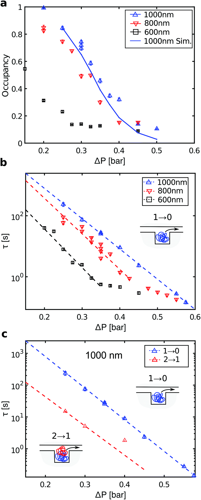 | ||
| Fig. 4 (a) Fractional occupancy at steady state as a function of pressure drop ΔP. (b) Characteristic waiting times for ‘1 → 0’ events for λ-DNA in arrays with different pit sizes. Error bars are standard errors on the means. Dashed lines are fit to a single exponential over the pressure drop range indicated by the lines themselves. (c) Characteristic waiting times for ‘1 → 0’ events (blue, same as in panel b) and ‘2 → 1’ events (red) in 1000 nm pits. | ||
The DNA concentration in the array at complete loading is 100 μg mL−1 corresponding to a 100-fold increase relative to the concentration in the microchannel. Higher loading can be achieved by increasing the pit depth. Increasing the total length of the array also increases the fraction of the DNA retained in the pit array, but it also lowers the local density of DNA (i.e. the fractional occupancy). Notice that the 1000 nm pit array in Fig. 2c contains 14.4 Mb of DNA. Thus a 0.6 mm2 array of 1000 nm pits could accommodate the whole genome of a human cell (2 × 3.2 Gb). While other micro-scale separation devices focus on larger volume samples that can be handled by pipetting, our device may be more suited to single genome applications where the cells components are eluted in nL volumes on chip.
DNA is released from the nanopits by increasing the flow velocity so that molecules move through the array without settling. We expect that there is a flow velocity beyond which the concentration of the DNA in the plug of solution cannot be increased since at high flow rates the mobility varies linearly with the pressure drop.13 Another interesting aspect of entropic trapping of double-stranded DNA is that it can be released by denaturation, either chemically or thermally, since the persistence length of DNA drops dramatically under the transition to its single-stranded form, which reduces the trapping effect.
The different pit sizes help to understand how a sample of DNA molecules with heterogeneous sizes would accumulate in a nanopit array. For λ-DNA, the 800 nm pits can at most be occupied by a single molecule, while the 1000 nm pits can hold up to two molecules (see ESI†). For the 600 nm pits and without flow, a single molecule can span two pits in an equilibrium configuration (see above). This shows that in order to accumulate a DNA sample with a broad size distribution at a constant flow rate, pit sizes should be varied through the array according to the size distribution of the incoming molecules.
3.4. Loading rates
For each pressure drop, we also recorded the intensity versus time at steady state for individual pits (ESI Fig. 2†). From these traces, we define two types of events: A ‘1 → 0’ event where a molecule enters an empty pit and then leaves it, and a ‘2 → 1’ event where a molecule enters a double-occupied pit and then leaves it. The distribution of waiting times twait, i.e. the times molecules reside in pits, is consistent with a single exponential distribution p(twait) = e−twait/τ (ESI Fig. 3†). The characteristic time scales for the two types of events are denoted τ1→0 and τ2→1, respectively. Fig. 4b shows a plot of the characteristic waiting times versus the applied pressure drop for ‘1 → 0’ events. For the 1000 nm pits, we observe a clear exponential dependence over the full range of applied pressures. For the 600 and 800 nm pits, the data also indicate an exponential dependence up to a certain pressure drop, followed by a crossover to another regime. Fig. 4c shows the waiting times for ‘2 → 1’ events in 1000 nm pits (red data points). These are approximately an order of magnitude lower than for ‘1 → 0’ events over the full range of applied pressures.According to transition state theory,10,11 the characteristic waiting time for hopping between two entropic traps depends exponentially on the maximum energy barrier which has to be crossed, τ = eΔFmax/kBT. Here ΔFmax is the activation barrier for the escape of a DNA molecule from the pit. If the traps are line-shaped grooves in a nanoslit, Vestergaard et al. demonstrated that the characteristic waiting time between so-called sidewinder transitions, i.e. where the molecule leaves the groove starting from one end, could be fitted with a two-parameter model.31 The model includes the drag force on the DNA in the slit and the entropy of DNA in the grooves and in the nanoslit, and all parameters have a well-defined microscopic origin. The model shows two different regimes, where below a critical pressure ΔPcrit holds ΔFmax ∝ −ΔP, thus the characteristic waiting times decay exponentially for an increasing applied pressure drop. For ΔP > ΔPcrit holds ΔFmax ∝ 1/ΔP. For λ-DNA in 1000 nm pits, we only observe the exponential dependence on the pressure drop for the ‘1 → 0’ events, while the results for the 600 and 800 nm pits show more than a single regime. No microscopic model is available for DNA jumping between nanopits embedded in a nanoslit in presence of a flow, but such a model will be more complex than for DNA in nanogrooves. For example, DNA in pits experience self-exclusion,23 which is not present for DNA in grooves, and the drag force on the DNA does not only affect one end of the DNA, as when DNA leaves a groove in a sidewinder transition.
3.5. Simulation
Finally, with a simple rate equation model we can simulate the fractional occupancy at steady state versus pressure for the 1000 nm pits. We assume that a pit can contain at most two molecules and that the model parameters are the rates for the two types of events, r1→0 = 1/τ1→0 and r2→1 = 1/τ2→1, and the rate of incoming molecules rin. The latter is obtained from the total number of molecules in the array before steady state, see ESI.† The rates for r1→0 and r2→1 are read off from the fits of the waiting times in Fig. 4c. The full curve in Fig. 4a shows the result of the simulation. It shows reasonable quantitative agreement with the experimental data, although some deviations occur at the highest pressure drops. For details of the simulation, see ESI.†4. Conclusions
In conclusion, an entropic trap array is designed to accumulate genomic DNA. It allows to (i) concentrate genomic DNA, (ii) exchange buffer to purify DNA, (iii) perform a chemical reaction on the DNA, and (iv) elute the concentrated DNA. Importantly, it does so without the need for external actuation such as dielectrophoresis or optics.9 An entropic trap array provides a higher density of single molecules (0.25 μm−2) compared to previous nanofluidic enzymatic assays.20,21 In addition, our assay is based on single-strand nicks rather than double-strand nicks, and thus preserves the lengths of the molecules. Single-strand nicks can be created intentionally on DNA by a sequence-specific enzyme.25 Thus our experiment is a step toward sequence-specific labeling for optical mapping. For example, methyltransferase32 can be combined with multicolour labels and provide high-resolution barcodes.19 Furthermore, the use of polymerase or ligase may enable other applications, such as sample preparation steps for sequencing-by-synthesis or the sequencing-by-synthesis itself where currently the enzyme or the DNA is attached to a surface.24 Single molecule enzymatic assays have been developed,33 and some of these could be implemented on DNA trapped in a nanofluidic array. So a nanofluidic chip that can store DNA will be a key technology enabling the integration of single cell microfluidics with analytical methods for single-molecule DNA analysis.Conflicts of interest
The authors declare no conflicts of interest.Acknowledgements
The authors gratefully acknowledge funding from the European Commission under the Seventh Framework Programme (FP7/2007-2013) under grant agreements number 278204 (Cellomatic) and H2020-FET Open under grant agreement 665233 (Chromavision).References
- D. R. Bentley, S. Balasubramanian, H. P. Swerdlow, G. P. Smith, J. Milton, C. G. Brown, K. P. Hall, D. J. Evers, C. L. Barnes, H. R. Bignell, J. M. Boutell, J. Bryant, R. J. Carter, R. K. Cheetham, A. J. Cox, D. J. Ellis, M. R. Flatbush, N. A. Gormley, S. J. Humphray, L. J. Irving, M. S. Karbelashvili, S. M. Kirk, H. Li, X. Liu, K. S. Maisinger, L. J. Murray, B. Obradovic, T. Ost, M. L. Parkinson, M. R. Pratt, I. M. J. Rasolonjatovo, M. T. Reed, R. Rigatti, C. Rodighiero, M. T. Ross, A. Sabot, S. V. Sankar, A. Scally, G. P. Schroth, M. E. Smith, V. P. Smith, A. Spiridou, P. E. Torrance, S. S. Tzonev, E. H. Vermaas, K. Walter, X. Wu, L. Zhang, M. D. Alam, C. Anastasi, I. C. Aniebo, D. M. D. Bailey, I. R. Bancarz, S. Banerjee, S. G. Barbour, P. A. Baybayan, V. A. Benoit, K. F. Benson, C. Bevis, P. J. Black, A. Boodhun, J. S. Brennan, J. A. Bridgham, R. C. Brown, A. A. Brown, D. H. Buermann, A. A. Bundu, J. C. Burrows, N. P. Carter, N. Castillo, M. C. E. Catenazzi, S. Chang, R. N. Cooley, N. R. Crake, O. O. Dada, K. D. Diakoumakos, B. Dominguez-Fernandez, D. J. Earnshaw, U. C. Egbujor, D. W. Elmore, S. S. Etchin, M. R. Ewan, M. Fedurco, L. J. Fraser, K. V. F. Fajardo, W. S. Furey, D. George, K. J. Gietzen, C. P. Goddard, G. S. Golda, P. A. Granieri, D. E. Green, D. L. Gustafson, N. F. Hansen, K. Harnish, C. D. Haudenschild, N. I. Heyer, M. M. Hims, J. T. Ho, A. M. Horgan, K. Hoschler, S. Hurwitz, D. V. Ivanov, M. Q. Johnson, T. James, T. A. H. Jones, G.-D. Kang, T. H. Kerelska, A. D. Kersey, I. Khrebtukova, A. P. Kindwall, Z. Kingsbury, P. I. Kokko-Gonzales, A. Kumar, M. A. Laurent, C. T. Lawley, S. E. Lee, X. Lee, A. K. Liao, J. A. Loch, M. Lok, S. Luo, R. M. Mammen, J. W. Martin, P. G. McCauley, P. McNitt, P. Mehta, K. W. Moon, J. W. Mullens, T. Newington, Z. Ning, B. L. Ng, S. M. Novo, M. J. O'Neill, M. A. Osborne, A. Osnowski, O. Ostadan, L. L. Paraschos, L. Pickering, A. C. Pike, A. C. Pike, D. C. Pinkard, D. P. Pliskin, J. Podhasky, V. J. Quijano, C. Raczy, V. H. Rae, S. R. Rawlings, A. C. Rodriguez, P. M. Roe, J. Rogers, M. C. R. Bacigalupo, N. Romanov, A. Romieu, R. K. Roth, N. J. Rourke, S. T. Ruediger, E. Rusman, R. M. Sanches-Kuiper, M. R. Schenker, J. M. Seoane, R. J. Shaw, M. K. Shiver, S. W. Short, N. L. Sizto, J. P. Sluis, M. A. Smith, J. E. S. Sohna, E. J. Spence, K. Stevens, N. Sutton, L. Szajkowski, C. L. Tregidgo, G. Turcatti, S. vandeVondele, Y. Verhovsky, S. M. Virk, S. Wakelin, G. C. Walcott, J. Wang, G. J. Worsley, J. Yan, L. Yau, M. Zuerlein, J. Rogers, J. C. Mullikin, M. E. Hurles, N. J. McCooke, J. S. West, F. L. Oaks, P. L. Lundberg, D. Klenerman, R. Durbin and A. J. Smith, Nature, 2008, 456, 53–59 CrossRef CAS PubMed.
- J. Eid, A. Fehr, J. Gray, K. Luong, J. Lyle, G. Otto, P. Peluso, D. Rank, P. Baybayan, B. Bettman, A. Bibillo, K. Bjornson, B. Chaudhuri, F. Christians, R. Cicero, S. Clark, R. Dalal, A. deWinter, J. Dixon, M. Foquet, A. Gaertner, P. Hardenbol, C. Heiner, K. Hester, D. Holden, G. Kearns, X. Kong, R. Kuse, Y. Lacroix, S. Lin, P. Lundquist, C. Ma, P. Marks, M. Maxham, D. Murphy, I. Park, T. Pham, M. Phillips, J. Roy, R. Sebra, G. Shen, J. Sorenson, A. Tomaney, K. Travers, M. Trulson, J. Vieceli, J. Wegener, D. Wu, A. Yang, D. Zaccarin, P. Zhao, F. Zhong, J. Korlach and S. Turner, Science, 2009, 323, 133–138 CrossRef CAS PubMed.
- A. R. Wu, N. F. Neff, T. Kalisky, P. Dalerba, B. Treutlein, M. E. Rothenberg, F. M. Mburu, G. L. Mantalas, S. Sim, M. F. Clarke and S. R. Quake, Nat. Methods, 2014, 11, 41–46 CrossRef CAS PubMed.
- Y. Xin, J. Kim, M. Ni, Y. Wei, H. Okamoto, J. Lee, C. Adler, K. Cavino, A. J. Murphy, G. D. Yancopoulos, H. C. Lin and J. Gromada, Proc. Natl. Acad. Sci. U. S. A., 2016, 113, 3293–3298 CrossRef CAS PubMed.
- L. Huang, J. Tegenfeldt, J. Kraeft, J. Sturm, R. Austin and E. Cox, Nat. Biotechnol., 2002, 20, 1048–1051 CrossRef CAS PubMed.
- Y. Chen, E. S. Abrams, T. C. Boles, J. N. Pedersen, H. Flyvbjerg, R. H. Austin and J. C. Sturm, Phys. Rev. Lett., 2015, 114, 198303 CrossRef PubMed.
- C. Prinz, J. Tegenfeldt, R. Austin, E. Cox and J. Sturm, Lab Chip, 2002, 2, 207–212 RSC.
- J. J. Benitez, J. Topolancik, H. C. Tian, C. B. Wallin, D. R. Latulippe, K. Szeto, P. J. Murphy, B. R. Cipriany, S. L. Levy, P. D. Soloway and H. G. Craighead, Lab Chip, 2012, 12, 4848–4854 RSC.
- A. H. J. Yang, S. D. Moore, B. S. Schmidt, M. Klug, M. Lipson and D. Erickson, Nature, 2009, 457, 71–75 CrossRef CAS PubMed.
- J. Han, S. W. Turner and H. G. Craighead, Phys. Rev. Lett., 2001, 86, 1394–1394 CrossRef CAS.
- J. Han, S. Turner and H. Craighead, Phys. Rev. Lett., 1999, 83, 1688–1691 CrossRef CAS.
- M. Cabodi, S. W. P. Turner and H. G. Craighead, Anal. Chem., 2002, 74, 5169–5174 CrossRef CAS PubMed.
- M. B. Mikkelsen, W. Reisner, H. Flyvbjerg and A. Kristensen, Nano Lett., 2011, 11, 1598–1602 CrossRef CAS PubMed.
- A. Kuchler, M. Yoshimoto, S. Luginbuhl, F. Mavelli and P. Walde, Nat. Nanotechnol., 2016, 11, 409–420 CrossRef CAS PubMed.
- M. Heiskanen, E. Hellsten, O. Kallioniemi, T. Makela, K. Alitalo, L. Peltonen and A. Palotie, Genomics, 1995, 30, 31–36 CrossRef CAS PubMed.
- R. Marie, J. N. Pedersen, D. L. V. Bauer, K. H. Rasmussen, M. Yusuf, E. Volpi, H. Flyvbjerg, A. Kristensen and K. U. Mir, Proc. Natl. Acad. Sci. U. S. A., 2013, 110, 4893–4898 CrossRef CAS PubMed.
- M. Baday, A. Cravens, A. Hastie, H. Kim, D. E. Kudeki, P.-Y. Kwok, M. Xiao and P. R. Selvin, Nano Lett., 2012, 12, 3861–3866 CrossRef CAS PubMed.
- A. R. Hastie, L. Dong, A. Smith, J. Finklestein, E. T. Lam, N. Huo, H. Cao, P.-Y. Kwok, K. R. Deal, J. Dvorak, M.-C. Luo, Y. Gu and M. Xiao, PLoS One, 2013, 8, e55864 CAS.
- C. Vranken, J. Deen, L. Dirix, T. Stakenborg, W. Dehaen, V. Leen, J. Hofkens and R. K. Neely, Nucleic Acids Res., 2014, 42, e50–e50 CrossRef CAS PubMed.
- R. Riehn, M. Lu, Y. Wang, S. Lim, E. Cox and R. Austin, Proc. Natl. Acad. Sci. U. S. A., 2005, 102, 10012–10016 CrossRef CAS PubMed.
- F. Persson, J. Fritzsche, K. U. Mir, M. Modesti, F. Westerlund and J. O. Tegenfeldt, Nano Lett., 2012, 12, 2260–2265 CrossRef CAS PubMed.
- P. Utko, F. Persson, A. Kristensen and N. B. Larsen, Lab Chip, 2011, 11, 303–308 RSC.
- W. Reisner, N. B. Larsen, H. Flyvbjerg, J. O. Tegenfeldt and A. Kristensen, Proc. Natl. Acad. Sci. U. S. A., 2009, 106, 79–84 CrossRef CAS PubMed.
- C. W. Fuller, L. R. Middendorf, S. A. Benner, G. M. Church, T. Harris, X. Huang, S. B. Jovanovich, J. R. Nelson, J. A. Schloss, D. C. Schwartz and D. V. Vezenov, Nat. Biotechnol., 2009, 27, 1013–1023 CrossRef CAS PubMed.
- M. Xiao, A. Phong, C. Ha, T.-F. Chan, D. Cai, L. Leung, E. Wan, A. L. Kistler, J. L. DeRisi, P. R. Selvin and P.-Y. Kwok, Nucleic Acids Res., 2007, 35, e16 CrossRef PubMed.
- J. O. Tegenfeldt, C. Prinz, H. Cao, S. Chou, W. W. Reisner, R. Riehn, Y. M. Wang, E. C. Cox, J. C. Sturm, P. Silberzan and R. H. Austin, Proc. Natl. Acad. Sci. U. S. A., 2004, 101, 10979–10983 CrossRef CAS PubMed.
- D. E. Streng, S. F. Lim, J. Pan, A. Karpusenka and R. Riehn, Lab Chip, 2009, 9, 2772–2774 RSC.
- S. F. Lim, A. Karpusenko, A. L. Blumers, D. E. Streng and R. Riehn, Biomicrofluidics, 2013, 7, 064105 CrossRef PubMed.
- S. F. Lim, A. Karpusenko, J. J. Sakon, J. A. Hook, T. A. Lamar and R. Riehn, Biomicrofluidics, 2011, 5, 034106 CrossRef PubMed.
- P. F. Ostergaard, J. Lopacinska-Jorgensen, J. N. Pedersen, N. Tommerup, A. Kristensen, H. Flyvbjerg, A. Silahtaroglu, R. Marie and R. J. Taboryski, J. Micromech. Microeng., 2015, 25, 105002 CrossRef.
- C. L. Vestergaard, M. B. L. Mikkelsen, W. Reisner, A. Kristensen and H. Flyvbjerg, Nat. Commun., 2016, 7, 10227 CrossRef CAS PubMed.
- R. K. Neely, P. Dedecker, J.-I. Hotta, G. Urbanaviciute, S. Klimasauskas and J. Hofkens, Chem. Sci., 2010, 1, 453–460 RSC.
- S. Kim, P. C. Blainey, C. M. Schroeder and X. S. Xie, Nat. Methods, 2007, 4, 397–399 CrossRef CAS PubMed.
Footnote |
| † Electronic supplementary information (ESI) available. See DOI: 10.1039/C7NR06016E |
| This journal is © The Royal Society of Chemistry 2018 |