
 Open Access Article
 This Open Access Article is licensed under a
 Creative Commons Attribution 3.0 Unported Licence
All inkjet-printed graphene-based conductive patterns for wearable e-textile applications†
Nazmul
Karim‡
 *ab,
Shaila
Afroj‡
ac,
Andromachi
Malandraki
c,
Sean
Butterworth
c,
Christopher
Beach
d,
Muriel
Rigout
b,
Kostya S.
Novoselov
a,
Alexander J.
Casson
d and
Stephen G.
Yeates
c
*ab,
Shaila
Afroj‡
ac,
Andromachi
Malandraki
c,
Sean
Butterworth
c,
Christopher
Beach
d,
Muriel
Rigout
b,
Kostya S.
Novoselov
a,
Alexander J.
Casson
d and
Stephen G.
Yeates
c
aThe National Graphene Institute (NGI), The University of Manchester, Booth Street East, M13 9PL, Manchester, UK. E-mail: mdnazmul.karim@manchester.ac.uk
bSchool of Materials, The University of Manchester, Oxford Road, M13 9PL, Manchester, UK
cSchool of Chemistry, The University of Manchester, Oxford Road, M13 9PL, Manchester, UK. E-mail: stephen.yeates@manchester.ac.uk
dSchool of EEE, The University of Manchester, Oxford Road, M13 9PL, Manchester, UK
First published on 6th October 2017
Abstract
Inkjet printing of graphene inks is considered to be very promising for wearable e-textile applications as benefits of both inkjet printing and extra-ordinary electronic, optical and mechanical properties of graphene can be exploited. However, the common problem associated with inkjet printing of conductive inks on textiles is the difficulty to print a continuous conductive path on a rough and porous textile surface. Here we report inkjet printing of an organic nanoparticle based surface pre-treatment onto textiles to enable all inkjet-printed graphene e-textiles for the first time. The functionalized organic nanoparticles present a hydrophobic breathable coating on textiles. Subsequent inkjet printing of a continuous conductive electrical path onto the pre-treated coating reduced the sheet resistance of graphene-based printed e-textiles by three orders of magnitude from 1.09 × 10⁶ Ω sq−1 to 2.14 × 10³ Ω sq−1 compared with untreated textiles. We present several examples of how this finding opens up opportunities for real world applications of printed, low cost and environmentally friendly graphene wearable e-textiles.
1. Introduction
Wearable electronic textiles (e-textiles) have become a focus of significant research interest due to their potential applications in sportswear, military uniforms, environmental monitoring and health care.1–3 There have been enormous efforts in incorporating electronic components to make e-textiles for various applications such as sensors,4–7 energy storage devices,8,9 transistors10 and photovoltaic devices.11,12 Metal inks based on Ag,13 Cu14 or Au15 are currently the most commonly used materials due to their higher electrical conductivity (σ), typically ∼105 S m−1.16 However, metal inks are expensive,17 environmentally unfriendly,18 not-biocompatible,19 and often require higher sintering temperature,20 which is incompatible with heat sensitive textile fabrics. Thus there exists a need for a low-cost, environmentally friendly and low temperature processing conductive material for wearable e-textile application. This is timely, as consultation in the Waste Electrical and Electronics Equipment Directive (WEEE)21 is currently determining the future regulation of printed electronics disposal.Recent studies have highlighted the potential of graphene for the fabrication of the next generation e-textiles.22–28 However, current technologies, based on multiple dip and dry26 or vacuum filtration methods,28 are extremely slow. Also the use of graphene/metal composite inks23 requires higher post reduction temperature.27–29 In addition, reduced graphene oxide (rGO) inks have the potential to produce durable and washable conductive e-textiles due to the hydrogen bonding between hydroxyl groups in cotton9,30 and residual oxygen containing groups in rGO.31 Recent studies on the reduction of graphene oxide (GO) on textiles have however used toxic reducing agents such as hydriodic acid,32 sodium borohydride and hydrazine.26 Therefore, there remains growing interest to develop a quick, scalable and low temperature processing of environmentally friendly e-textiles.
For e-textile fabrication, inkjet printing offers a number of advantages over conventional manufacturing techniques including weaving of conductive yarn such as: the ability to deposit controlled quantities of materials at precise locations at and in the fabric, combined with a reduction in both material waste and water utilisation.33 However, the key challenge with inkjet printing of e-textiles is the ability to achieve continuous highly conductive electrical tracks on a rough and porous textile substrate. Textile fabrics demonstrate an intrinsic planar anisotropy of the general properties due to the orientation of fibres or yarns.34 In addition, the morphology of the fibre changes constantly due to the exchange of water molecules with surroundings, making it extremely difficult to produce uniform and continuously conductive paths using low viscosity inkjet inks.35
A previous study has suggested using a screen-printed polyurethane acrylate-based 200 μm thick interface layer, which reduces both the surface roughness and porosity of standard 65/35 polyester/cotton fabric,35 enabling inkjet printing of a continuous conductive track with a suitable silver ink on pre-treated areas. However the deposition of the interface layer by traditional screen printing constrains the potential feature resolution, is not compatible with the deposition of low quantities of material and is not compatible with future roll to roll manufacturing.36
Here we report an organic nanoparticle based inkjet printable textile surface pre-treatment which enables all inkjet-printed graphene-based wearable e-textiles that are breathable, comfortable and environmentally friendly. The primary advantage of inkjet deposition of the surface pre-treat over techniques such as screen printing and curtain coating is the ability to deposit only where required on the article and to personalise at an item by item level. Such a pre-treatment acts as a receptor layer for water-based rGO inks, which can subsequently be dried at low temperature (100 °C); thus reducing the chance of damaging heat-sensitive fabrics. As illustrated in Fig. 1, an organic nanoparticle textile pre-treatment is inkjet-printed onto the textile fabric, followed by a rGO water-based ink prepared using a green non-toxic reducing agent, L-ascorbic acid in the presence of polyvinyl alcohol (PVA). The resultant conductive tracks have sufficient conductivity for uses in wearable power delivery systems and non-invasive heart monitoring.
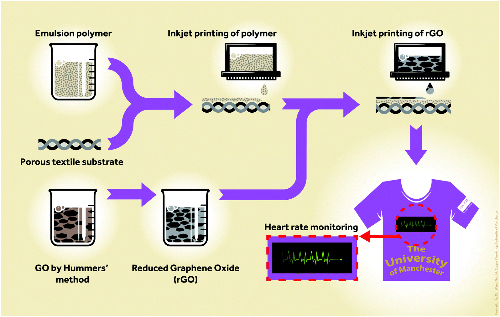 | ||
| Fig. 1 Schematic diagram of the all inkjet-printed graphene e-textile manufacturing process. | ||
2. Experimental
2.1 Materials
Styrene (St), divinylbenzene (DVB), hydroxyethyl methacrylate (HEMA), sodium dodecyl sulphate (SDS), ammonium persulfate (APS), glycerol, polyvinyl alcohol (PVA, Mw ∼ 31![[thin space (1/6-em)]](https://www.rsc.org/images/entities/char_2009.gif) 000–50000, 98–99%), L-ascorbic acid (99%), ammonia, silver nanoparticle inks (30–35 wt%, Sigma Aldrich Product No. 736473) and Triton X-100 were purchased from Sigma-Aldrich, UK and used as received. Flake graphite (Grade 3061) was kindly donated by Asbury Graphite Mills, USA. 100% Cotton, 100% Polyester and 65/35 cotton–polyester blend (65% cotton, 35% polyester) fabrics were provided by Royal TenCate, Netherlands.
000–50000, 98–99%), L-ascorbic acid (99%), ammonia, silver nanoparticle inks (30–35 wt%, Sigma Aldrich Product No. 736473) and Triton X-100 were purchased from Sigma-Aldrich, UK and used as received. Flake graphite (Grade 3061) was kindly donated by Asbury Graphite Mills, USA. 100% Cotton, 100% Polyester and 65/35 cotton–polyester blend (65% cotton, 35% polyester) fabrics were provided by Royal TenCate, Netherlands.
2.2 Nanoparticle synthesis (NP1)
Hydroxyl functionalised cross-linked styrene/divinylbenzene nanoparticles were synthesized using conventional emulsion polymerisation containing 1 wt% HEMA (NP1) based on the total monomer. 250 mL of deionised water and 20 mL of a 3.38 mmol, solution of SDS were added to a 500 mL flange flask fitted with a condenser, nitrogen flow, a 5 blade impeller mechanical stirrer and a thermometer; stirred for 15 min at 600 rpm under nitrogen flow. St (21 g, 216 mmol), DVB (2.1 g, 16.1 mmol) and HEMA were then added and stirred at 600 rpm whilst being degassed for 1 hour and heated to 80 °C. APS (1 g, 11.6 mmol), dissolved in 10 mL of deionised water and degassed for 30 min in a vial, was added to the reaction flask. The reaction was run for 24 hours; stopped and run for another 2 hours for cooling. The resultant suspension was passed through a 50 μm nylon gauze to remove any coagulant and nanoparticles were used without any further treatment.2.3 Synthesis of graphene oxide and reduced graphene oxide
Graphene oxide (GO) was prepared using the modified Hummers method as described elsewhere.37 A 80 mg amount of GO was added to 160 mL of deionized (DI) water and sonicated for 30 min to form a brown dispersion of graphene oxide (0.5 mg mL−1). Further, 500 mg of PVA was mixed to the graphene oxide dispersion with rigorous stirring. This was transferred to a round-bottom flask placed in an oil bath. L-Ascorbic acid (1.2 gm) and NH3 (as required to adjust pH 9–10) were added to the dispersion with rigorous stirring. This mixture was heated at 90 °C for 24 hours under closed conditions to obtain a black dispersion. Sufficient DI water was added to this dispersion in order to make a total volume of 200 mL. The resulted rGO was washed with deionised water several times to remove any residues present and finally dispersed into water at a desired concentration.2.4 Inkjet ink formulation and inkjet printing
The viscosity and surface tension of NP1 were corrected adding glycerol (19.8 wt%) as a rheology modifier and a humectant, and Triton X-100 (1.2 wt%) as a non-ionic surfactant to achieve 2.55 ± 0.05 mPa s and 31 mN m−1, respectively. All inks were filtered through a 2.0 μm filter to remove any impurities and large particles that could block Dimatix nozzles.The viscosity and surface tension of rGO ink was found to be 1.35 mPa s and 65 mN m−1, respectively. rGO ink was printed without any modification by increasing the firing voltage in the first segment of drop generation to enable rapid pressure build up for drop ejection. The voltage was decreased slowly in the second segment to cut off droplet tails; thus forming spherical droplets.38
A Dimatix DMP-2800 inkjet printer (Fujifilm Dimatix Inc., Santa Clara, USA) was used in this study, equipped with a disposable piezo “inkjet” cartridge. This printer can create and define patterns over an area of about 200 × 300 mm and handle substrates up to 25 mm thick, being adjustable in the Z direction. The nozzle plate consists of a single row of 16 nozzles of 21.5 μm diameter spaced 254 μm with a typical drop diameter of 27 μm and a 10 pL drop size. The print head height was adjusted to 0.75 mm; formulated inks were jetted reliably and reproducibly at 24 V and ambient temperature. It was important however to use the primed-head within 48 hours to avoid non recoverable nozzle dry out.
2.5 Characterisation
The surface wettability of untreated and nanoparticle (NP1) printed textile substrates was assessed by measuring the contact angle (CA) using droplets of distilled water and rGO ink on the untreated and printed substrates, and the change of CA with time was also measured using a Kruss Dynamic Shape Analyser DSA100. The CA readings were taken approximately every 5 min. A Jandel four-point probe system (Jandel Engineering Ltd, Leighton, UK) was employed to measure the resistivity of the conductive pattern; sheet resistance was calculated from the average of six measurements. For SEM, AFM and Raman, the rGO dispersion was diluted 1000 times and drop cast on Si/SiO2 (290 nm oxide on plain silicon). A Philips XL 30 Field Emission Gun Scanning Electron Microscope (SEM) was used to analyse the surface topography of the untreated and printed cotton fabrics, and also the flake size of GO and rGO. A Dimension Icon (Bruker) Atomic Force Microscopy (AFM) was used to determine the flake thickness. For each sample, images were taken at 10 different locations on the sample and a statistical analysis of 100 flakes was done. Raman spectra were captured using a Renishaw Raman System equipped with a 633 nm laser. A Kratos Axis system spectrophotometer was used to perform the XPS analysis.The breathability of the printed and untreated cotton fabrics was assessed by adding a known amount of water in a pre-weighed vial using printed and untreated fabric as a lid. The vials were left idle on the bench and the weight loss was measured frequently for 14 days. A Zwick/Roell Tensile Tester (Zwick Roell Group, Germany) was used to control the cord length of NP1 and rGO inkjet-printed conductive fabric (Length: 28 mm) during the bending test. A National Instrument 9219 data acquisition card (NI, American) was used to capture the change of sheet resistance of printed fabric (Length: 28 mm) during bending in both forward and reverse directions. The wash stability of NP1 and rGO inkjet-printed fabric was performed by following the EN ISO 105 C06 A1S standard.
2.6 Electrocardiography (ECG) measurements
Measurements of electrocardiography (ECG) were performed on four male subjects for five minute recording periods. Each subject placed one finger from each hand on a printed graphene patch with both patches also connected to a standard two electrode wire ECG recording unit (CamNtech, Cambridge, UK). Signals were acquired at 10 bit resolution and a 1024 Hz sampling rate, downsampled to 256 Hz prior to analysis in Matlab (The MathWorks, Natick, USA). All signals were filtered (Butterworth, second order) to remove mains interference. On one hand, selected by the participant for comfort, subjects also wore a photoplesmography (PPG) heart rate monitor (Empatica, Boston, USA) as a reference device. PPG is the method of heart monitoring commonly used in smart watches and is used as the reference here as it does not introduce any interference to a simultaneous ECG recording.Heart rate estimates were extracted by taking the Continuous Wavelet Transform (CWT) at scale 0.025 using the Mexican hat mother wavelet and thresholding the CWT power coefficients to identify candidate peaks in the ECG trace (R peaks) corresponding to each heart-beat. From each candidate beat detection in the CWT domain, the actual R peak location was selected as the signal point in the time domain with the maximum amplitude within 10 samples of the CWT peak location. Spurious low (<50 μV) and high (>1000 μV) amplitude candidate peaks were rejected. The heart rate in beats per minute (bpm) was then calculated as 60 divided by the time between each pair of detected heart beats. As a final processing step, a simple tracking filter was applied which would reject heart rate estimates that were more than 10 bpm away from the previous estimate, with the rejected samples replaced with a zero order hold of the previous rate. The Signal-to-Noise Ratio was calculated for each detected heart beat by detrending the ECG trace and taking the resulting R peak amplitude as the Signal (S), and Root Mean Square of the middle third of the ECG trace between consecutive pairs of R peaks as the Noise (N), in the equation:
3. Results and discussion
The organic nanoparticle pre-treat is based upon a hydroxyl functional polystyrene emulsion polymer (NP1) having a Z-average particle size of 63.12 nm (polydispersity index = 0.05), Fig. 2a. NP1 as made has a %-solids = 40.86 wt% giving a viscosity of 0.5 mPa s and a surface tension of 70 mN m−1 at 25 °C. The viscosity and surface tension were subsequently modified by adding glycerol (19.8 wt%) and Triton X-100 (1.2 wt%) to achieve a viscosity of 2.5 mPa s and a surface tension of 31 mN m−1, respectively, which are suitable for stable inkjet printing using a Dimatix DMP inkjet printer. The formulations were inkjettable and form stable drops without satellites, although 12 multiple passes were required to achieve the required surface properties whilst retaining the mechanical properties without impairing the breathability of textiles.39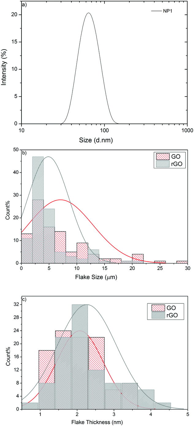 | ||
| Fig. 2 (a) Particle size distribution of NP1; (b) flake size distribution of GO and rGO; (c) flake thickness distribution of GO and rGO. | ||
Graphene oxide (GO) has previously been used in several studies to coat textiles and reduced to rGO by electrochemical,25,40,41 thermal,42–45 UV46 or chemical processes26,47–49 to make conductive e-textiles. Here, we use chemical reduction of GO prepared using the Hummers method50,51 to rGO using a green and efficient reducing agent, vitamin C52 and stabilised by polyvinyl alcohol (PVA). The resultant fluids are stable to sedimentation for over six months under ambient conditions. The structure and properties of graphene are partially restored by reducing GO to rGO; however full reduction or restoration of graphene properties is difficult to achieve.53 Therefore, it leaves some oxygen containing functional groups in rGO. The presence of these residual oxygen functional groups however is beneficial as it helps to create hydrogen bonding with hydroxyl groups of cotton fibres,30 which enables uniform and durable coatings on textile fibres.32
Statistical analysis of 100 flakes using Scanning Electron Microscopy (SEM) shows that the mean lateral dimension of GO is 5.85 μm and that of rGO is 4.86 μm (Fig. 2b). Atomic Force Microscopy (AFM) was used to measure the thickness (height = h) of GO and rGO flakes, which shows that the mean thickness for GO is 2.07 nm and rGO is 2.26 nm, confirming the presence of single to few layers of graphene flakes in the dispersion. The statistical analysis in Fig. 2c reveals that the distribution is shifted towards higher h for rGO, may be due to the presence of the cross-linking polymer (PVA) covering graphene flakes, which is in agreement with a previous study.54 The Raman spectra of GO and rGO display characteristic peaks at 1344.78 cm−1 and 1605.95 cm−1, corresponding to D and G bands (ESI,† Fig. S1). These two peaks were shifted to lower wavenumbers 1327.4 cm−1 (D) and 1596.82 cm−1 (G) after reduction of GO to rGO, which may be due to the recovery of hexagonal carbon atoms.55 In addition, the intensity ratio of the D to G band (ID/IG) was increased from 0.98 for GO to 1.73 for rGO, which suggests the generation of a large number of sp2 domains in rGO.
The wide scan XPS spectra in Fig. 3a also provide evidence of the reduction process as the C/O ratio increased from 2.41 (GO) to 4.18 (rGO). The C1s spectra of GO, Fig. 3b, demonstrate two main peaks which can be fitted into three components emerging from the C–C/C![[double bond, length as m-dash]](https://www.rsc.org/images/entities/char_e001.gif) C bond in aromatic rings (∼284.6 eV), C–O epoxy and alkoxy groups (∼286.4 eV) and CO carbonyl groups (288 eV).31,56 This provides proof of a higher number of oxygen containing functional groups present on the surface of GO. After reduction to rGO, the peaks associated with oxygen functional groups sharply decreased, with a small amount of residual oxygen functional groups left around 288.5 eV, Fig. 3b. In general, the C1s spectrum of rGO exhibits a similar shape to graphene or natural graphite, which indicates remarkable restoration of the graphitic structure through chemical reduction.55
C bond in aromatic rings (∼284.6 eV), C–O epoxy and alkoxy groups (∼286.4 eV) and CO carbonyl groups (288 eV).31,56 This provides proof of a higher number of oxygen containing functional groups present on the surface of GO. After reduction to rGO, the peaks associated with oxygen functional groups sharply decreased, with a small amount of residual oxygen functional groups left around 288.5 eV, Fig. 3b. In general, the C1s spectrum of rGO exhibits a similar shape to graphene or natural graphite, which indicates remarkable restoration of the graphitic structure through chemical reduction.55
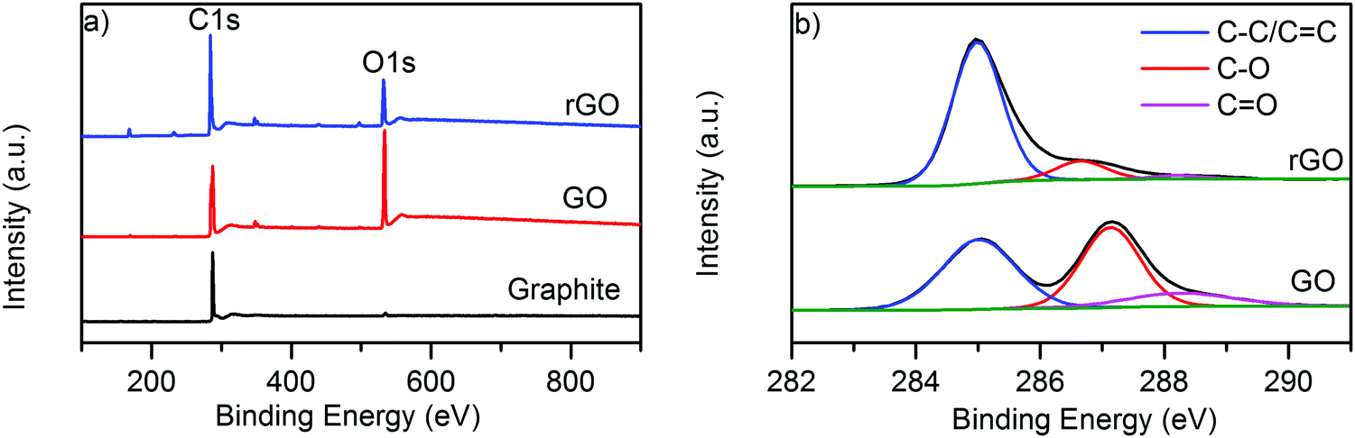 | ||
| Fig. 3 (a) Wide scan XPS spectra of graphite, GO and rGO; and (b) high resolution C1s spectra of GO and rGO. | ||
The inkjet printing of NP1 onto a range of textile materials such as cotton (Fig. 4a), cotton–polyester fabrics (Fig. 4b), and polyester (Fig. 4c) substantially increased the water contact angle (WCA), for example with 100% cotton fabrics up to 132.9°. During contact angle measurement, the water droplets falling onto an untreated control cotton fabric were absorbed almost immediately after hitting the surface, Fig. 4a, as the cotton fibres provide higher polarity, hydrogen-bonding and wettability in their natural form. In addition, untreated cotton fibres are extremely hydrophilic due to the presence of abundant hydroxyl groups in their cellulosic molecules.39 Moreover, textile surfaces are not only rough but also porous which allows the liquid penetration, controlled by kinetics of wetting.57
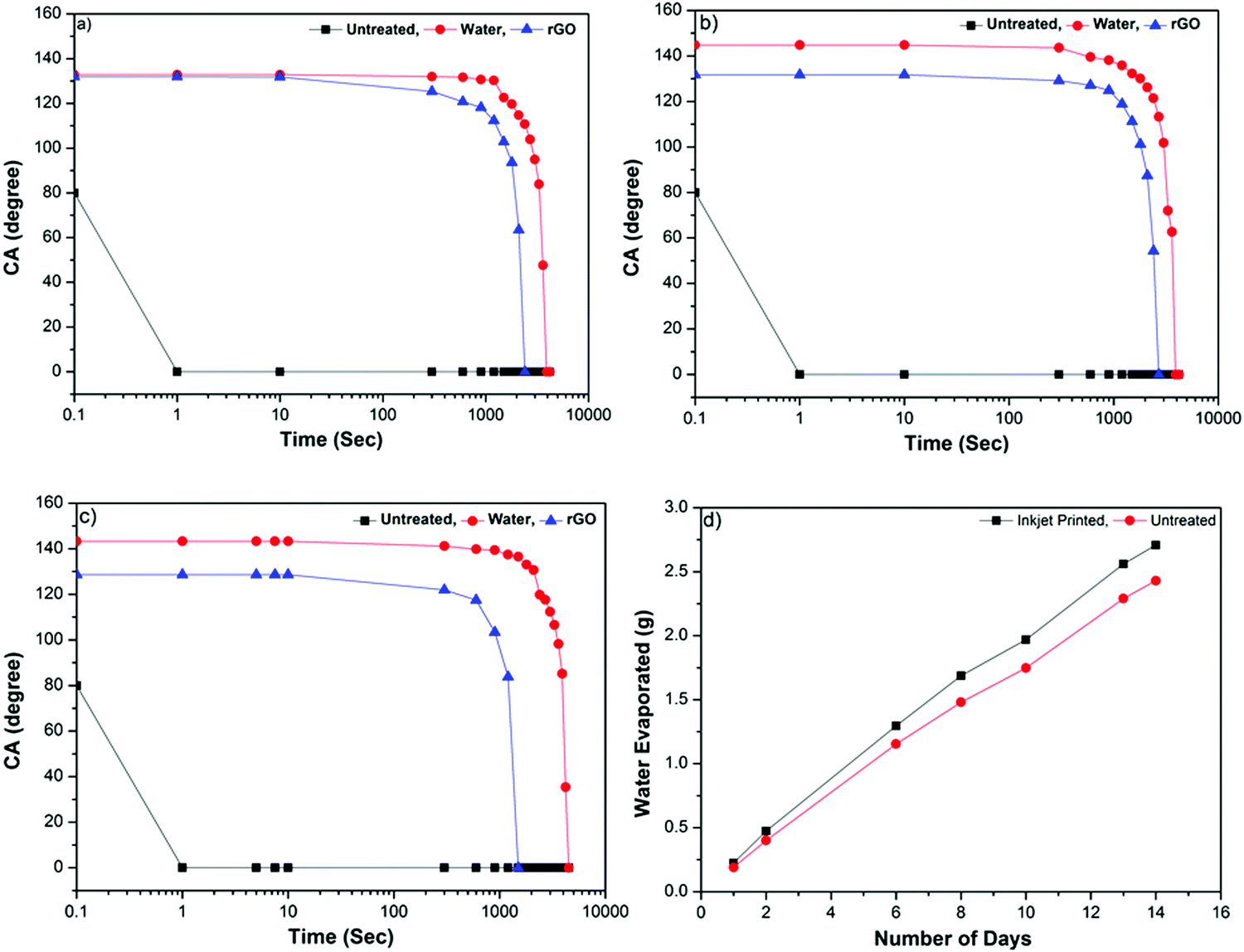 | ||
| Fig. 4 Contact angle (CA) of distilled water and rGO versus time at 25 °C on inkjet-printed (a) cotton, (b) cotton–polyester (65/35) and (c) polyester fabrics with nanoparticles NP1: (■) control fabric (water and rGO), (●) WCA on NP1 printed fabric and (▲) CA of rGO on NP1 printed fabric; (d) the water evaporated through NP1 printed (12 layers) and untreated cotton fabrics: (■) inkjet printed with NP1 and (●) control fabrics. | ||
Coating with NP1 results in a larger interface area and produces mechanical locking,57 thus stopping liquid penetration through the fibres and holds water-based liquid on the surface. In contrast to cotton, the cotton–polyester (65/35) and polyester fabrics imparted a relatively higher WCA of 144.8° (Fig. 4b) and 143.3° (Fig. 4c), respectively. The superior WCA onto NP1 printed cotton–polyester and polyester fabrics is attributed to the inherent hydrophobicity of synthetic fibres in particular polyester.58 The non-wettability of hydrophobic polyester fibres is further enhanced by nanoparticle treatment; thus resulting in an increased surface roughness and imparting a higher WCA.
Fig. 4(a–c) shows that the contact angle of the rGO ink is almost similar on fabrics of all types, 131.9° for cotton, 131.7° for cotton–polyester and 128.6° for polyester. For 100% cotton fabric, the contact angle of the rGO ink decreased slightly compared with water; whereas that of cotton–polyester and polyester decreased significantly (by ∼12–15°) maybe due to the lower surface tension.38 Inkjet printing enables deposition of functional materials in a precise and controlled manner on desired locations (pattern), depositing functional materials only on the printed side. Fig. 4d illustrates that the weight of the water evaporated through inkjet nanoparticle (NP1) printed and untreated cotton fabrics. The results from the breathability test show that the permeability of water vapour through textiles was not obstructed due to the inkjet deposition of nanoparticles (NP1) onto textiles, as the water evaporation through both types of fabric was found to be similar. The unprinted side remains hydrophilic, thus providing additional comfort by regulating the moisture.59
A commercial silver inkjet ink (30–35 wt%, Sigma Aldrich Product No. 736473) was used first to evaluate the performance of NP1 printed surface pre-treatment on cotton for e-textile applications. The viscosity (10–18 cP) and surface tension (35–40 mN m−1) of silver inkjet inks were well within the required range for DMP. Conductive patterns were inkjet-printed onto the NP1 printed area and the untreated area of the fabric. The NP1 printed surface provides very good conductivity, Fig. 5b (2), although a few layers (6 layers) of silver inks were required to achieve lower sheet resistance. However, the untreated area of the cotton fabrics, Fig. 5b (3), results in no conductivity even with multi-layers of silver ink. The sheet resistance on the NP1 printed surface with 6 layers of commercially available silver inkjet ink was found to be 1.18 Ω sq−1. SEM images, Fig. 5(a and c), of inkjet-printed cotton fabrics with silver demonstrate the deposition of conductive silver nanoparticles on the fibre surface and the formation of a continuous film onto NP1 printed textiles. The inter-fibre bonding achieved through printing and curing of the NP1 polymer provided a continuous conductive film, Fig. 5c; however no such continuous film was observed for the fabrics without nanoparticle prints, Fig. 5a.
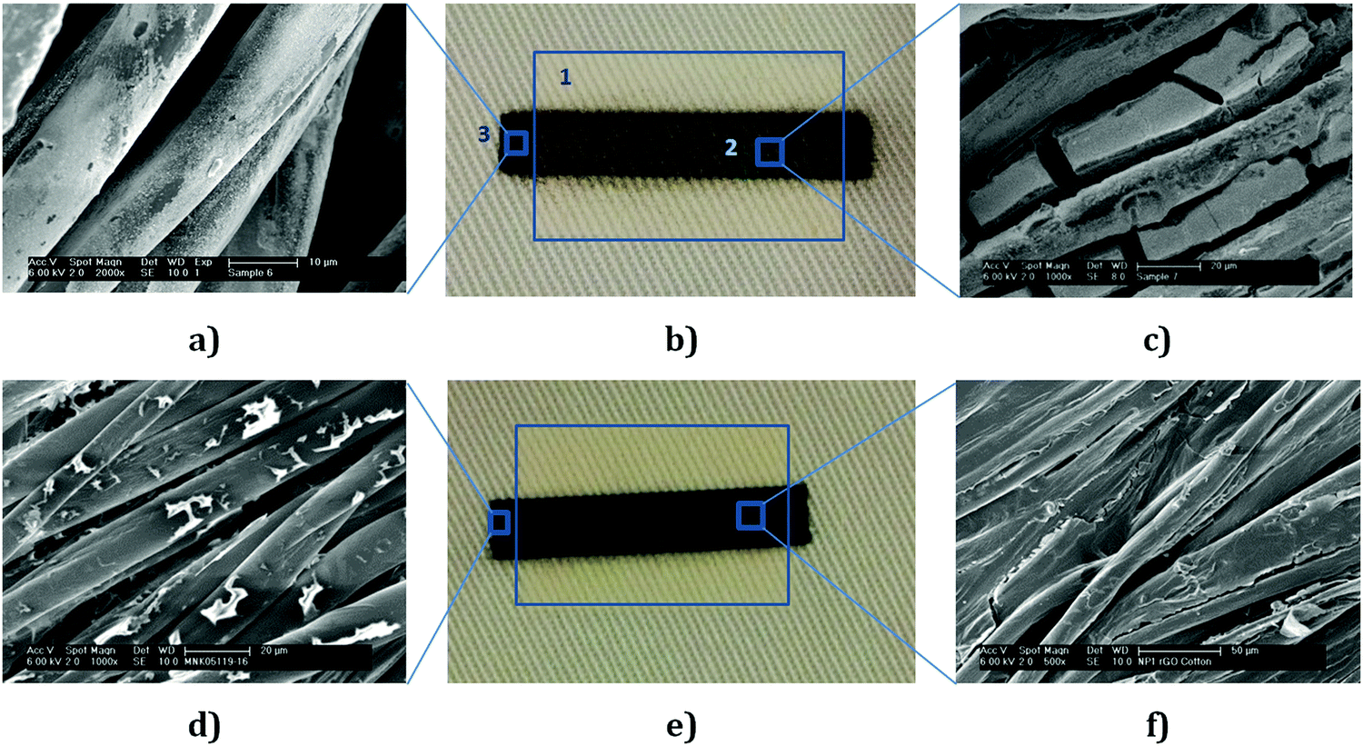 | ||
| Fig. 5 (a) SEM images of the inkjet printed silver ink (6 layers) onto untreated cotton (×2000); (b): (1) NP1 (12 layers) printed area; (2) inkjet-printed conductive pattern onto NP1 printed area with silver ink (6 layers) and (3) inkjet-printed silver ink onto untreated area (6 layers); (c) SEM images of the inkjet printed silver ink (6 layers) onto NP1 (12 layers) printed cotton fabrics (×1000); (d) SEM images of the inkjet printed rGO ink (6 layers) onto untreated cotton (×1000); (e) inkjet-printed conductive pattern with rGO onto NP1 printed and untreated area of cotton; (f) SEM images of the inkjet printed rGO ink (6 layers) onto NP1 (12 layers) printed cotton fabrics (×500). | ||
In order to inkjet print rGO, the ink concentration was adjusted with water to ∼1 mg mL−1 after post reduction washing cycles giving a viscosity and surface tension of the rGO composite ink 1.35 mPa s and 65 mN m−1, respectively. This formulation was inkjet-printed by manipulating the firing voltage of the piezoelectric nozzles as a function of time.38 We inkjet print the rGO ink onto the NP1 printed area and the untreated area of the cotton fabric. The sheet resistance of NP1 printed textiles with 6 layers (6L) of the rGO ink was found to be 2.14 × 10³ Ω sq−1; whereas untreated textiles provide a much higher sheet resistance of 1.09 × 10⁶ Ω sq−1, Table 1.
| Formulation | Fabrication and surface treatment | R s (Ω sq−1) | Standard deviation |
|---|---|---|---|
| rGO | Inkjet-printed (6 layers) onto 100% cotton fabric without NP1 surface pre-treatment | 1.09 × 10⁶ | 0.51 |
| rGO | Inkjet-printed (6 layers) onto 100% cotton fabric with printed NP1 (12 layers) surface pre-treatment | 2.14 × 10³ | 0.91 |
| SA-Ag | Inkjet-printed (6 layers) onto 100% cotton fabric without NP1 surface pre-treatment | Not conductive | — |
| SA-Ag | Inkjet-printed (6 layers) onto 100% cotton fabric with printed NP1 (12 layers) surface pre-treatment | 1.18 | 0.25 |
The rGO ink contains residual hydroxyl or carboxyl groups which may form hydrogen bonding with abundant hydroxyl groups of cellulosic fibres, Fig. 5d. Therefore, it helped to provide some electrical conductivity even onto untreated textiles; however electrical conductivity significantly improved by three orders of magnitude with NP1 surface pre-treatment. The inkjet printing of hydrophobic NP1 onto cotton fabrics provided inter-fibre bonding, Fig. 5f, which helped to produce a continuous conductive path and imparted very good inter-connections between graphene sheets. Therefore, the sheet resistances of the conductive patterns onto NP1 printed cotton were found to be much lower.
In order to demonstrate a potential application of all inkjet-printed graphene e-textiles, an LED light was illuminated by connecting it with a power supply and conductive e-textiles as shown in Fig. S4 (ESI†), requiring the delivery of milliamps current. To demonstrate functional sensing, multiple patches of the rGO ink were inkjet-printed onto a 100% cotton substrate with NP1 surface pre-treatment and used to perform electrocardiography (ECG) sensing of the heart. Each patch of the pre-treated material and rGO ink were electrically isolated by the cotton substrate and so act as separate electrodes. When these electrodes are placed on either side of the body, they measure the electrical activity due to the pumping action of the heart, which allows heart rate and heart rate variability information to be extracted, of significant use in a number of clinical and fitness applications of wearable technologies.60,61Fig. 6 illustrates an example of collected signal showing that high quality heart recordings can be obtained, with the average Signal-to-Noise Ratio maintained over 21 dB, and compared to a reference heart rate monitor the estimated heart rate is accurate to within 2.1 beats per minute (bpm). This performance is quantified with data from four different subjects in Table 2.
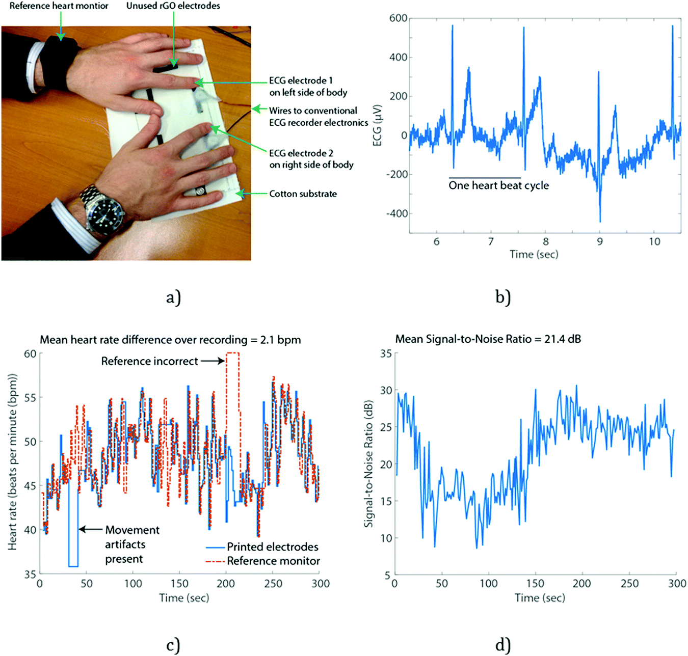 | ||
| Fig. 6 Heart rate monitoring example using graphene e-textiles: (a) experimental methods with two fingers placed on printed graphene patches; (b) illustrative section of the signal collected shows clear peaks due to each heart beat; (c) the estimated heart rate using the collected signal compared to a reference device and (d) quantified quality of the collected signal over time. | ||
| Subject | Mean heart rate estimation error (bpm) | Standard deviation of heart rate estimation error (bpm) | Mean signal-to-noise ratio of collected signal (dB) | Standard deviation signal-to-noise ratio of collected signal (dB) |
|---|---|---|---|---|
| 1 | 2.1 | 3.5 | 21.4 | 5.2 |
| 2 | 5.2 | 6.1 | 27.0 | 2.6 |
| 3 | 1.1 | 1.1 | 15.5 | 3.3 |
| 4 | 6.0 | 6.7 | 15.1 | 3.4 |
| Avg. | 3.6 | 4.4 | 22.3 | 3.6 |
To our knowledge, only a very limited number of papers have demonstrated graphene, in any form, for enabling heart rate monitoring. Celic et al.62 coated conventional Ag/AgCl metal electrodes with graphene to improve the quality of collected signals, but not in a manner suitable for textile wearable applications. Lou et al.63 used a polyethylene terephthalate (PET) substrate and secured the electrodes in place securely using bandages, unsuitable for wearable textile applications and forcing contact with the skin by using an adhesive bandage substantially improves signal quality regardless of the electrode formulation. Yapici et al.64 used a textile substrate, but specially selected nylon due to its minimum surface roughness. In contrast our all inkjet-printed pre-treatment overcomes this and allows the deposition of materials onto cotton fabrics.
Fig. 7 shows the change in the resistance of NP1 and rGO printed cotton fabrics (Length: 28 mm) under bending with concave down at various cord lengths. The resistance increased with the increase of cord lengths. The change in the resistance is repeatable in both forward (bending) and reverse (bending back) directions. Moreover, there was no observable crack on the printed pattern, which demonstrates the suitability of the device to be used as flexible wearable e-textiles.29 The inset picture in Fig. 7 shows excellent mechanical flexibility of NP1 and rGO printed conductive fabrics. It also demonstrates good drapability as conductive fabric can hang under its own weight and goes back to its original position once bending force is removed. The washability test of NP1 and rGO inkjet-printed cotton fabric shows that the fabric resistance increased with the increase of the number of washing cycles (ESI,† Fig. S5); however it survived 10 home laundry washing cycles. The wash stability NP1 treatment and the rGO printed conductive track could further be improved by incorporating additional functionality into the fabric surface and coating with an encapsulation polymer layer, respectively.
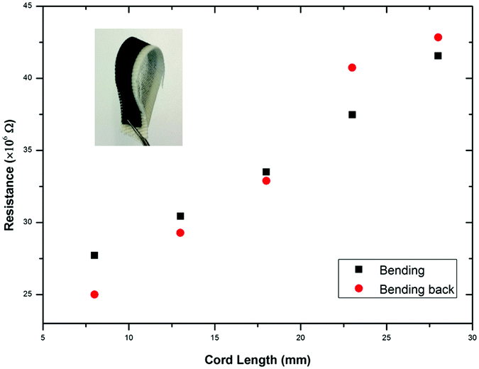 | ||
| Fig. 7 The variation in resistance in forward (bending) and reverse (bending back) directions (inset: flexible all inkjet-printed graphene ECG electrode). | ||
4. Conclusions
We report all inkjet-printed graphene-based e-textiles for the first time and demonstrate two potential wearable electronics applications. The surface pre-treatment with inkjet-printed NP1 significantly improved the electrical conductivity. All inkjet printing of surface pre-treatment enabled layer by layer deposition of an exact amount of materials at predefined locations. Moreover, inkjet printing of water-based and bio-compatible graphene inks could potentially open up opportunities to manufacture environmentally friendly next generation e-textiles for sports, healthcare and military applications.Conflicts of interest
There are no conflicts to declare. The institutional review board in Manchester has approved Dr Casson to perform ECG measurements.Acknowledgements
Authors kindly acknowledge the University of Manchester Research Impact Scholarship and Knowledge Exchange Fellowship (Graphene) for Dr Nazmul Karim and the Government of Bangladesh for PhD Scholarship of Shaila Afroj. Authors also acknowledge UK Engineering and Physical Science Research Council (EPSRC) (EP/N010345/1 and EP/J000825/1) and EU Graphene Flagship Program for supporting this work. Authors would like to thank Dr Paul Wiper and Daniel Wand for the help with LED demo and graphics, respectively.References
- K. Jost, G. Dion and Y. Gogotsi, J. Mater. Chem. A, 2014, 2, 10776–10787 CAS.
- Z. L. Wang and W. Wu, Angew. Chem., Int. Ed., 2012, 51, 11700–11721 CrossRef CAS PubMed.
- W. Zeng, L. Shu, Q. Li, S. Chen, F. Wang and X. M. Tao, Adv. Mater., 2014, 26, 5310–5336 CrossRef CAS PubMed.
- Y. Cheng, R. Wang, J. Sun and L. Gao, Adv. Mater., 2015, 27, 7365–7371 CrossRef CAS PubMed.
- Y. Wang, L. Wang, T. Yang, X. Li, X. Zang, M. Zhu, K. Wang, D. Wu and H. Zhu, Adv. Funct. Mater., 2014, 24, 4666–4670 CrossRef CAS.
- J. J. Park, W. J. Hyun, S. C. Mun, Y. T. Park and O. O. Park, ACS Appl. Mater. Interfaces, 2015, 7, 6317–6324 CAS.
- C. S. Boland, U. Khan, C. Backes, A. O’Neill, J. McCauley, S. Duane, R. Shanker, Y. Liu, I. Jurewicz, A. B. Dalton and J. N. Coleman, ACS Nano, 2014, 8, 8819–8830 CrossRef CAS PubMed.
- L. Liu, Y. Yu, C. Yan, K. Li and Z. Zheng, Nat. Commun., 2015, 6, 7260 CrossRef CAS PubMed.
- A. M. Abdelkader, N. Karim, C. Vallés, S. Afroj, K. S. Novoselov and S. G. Yeates, 2D Mater., 2017, 4, 035016 CrossRef.
- T. H. Yoo, B. I. Sang and D. K. Hwang, J. Korean Phys. Soc., 2016, 68, 599–603 CrossRef CAS.
- Z. Yang, Pure and Applied Chemistry, 2016, vol. 88, p. 113 Search PubMed.
- N. Zhang, J. Chen, Y. Huang, W. Guo, J. Yang, J. Du, X. Fan and C. Tao, Adv. Mater., 2016, 28, 263–269 CrossRef CAS PubMed.
- Y. Bayram, Y. Zhou, B. S. Shim, S. Xu, J. Zhu, N. A. Kotov and J. L. Volakis, IEEE Trans. Antennas Propag., 2010, 58, 2732–2736 CrossRef.
- J. W. Han and M. Meyyappan, AIP Adv., 2011, 1, 032162 CrossRef.
- A. Schwarz, J. Hakuzimana, A. Kaczynska, J. Banaszczyk, P. Westbroek, E. McAdams, G. Moody, Y. Chronis, G. Priniotakis, G. De Mey, D. Tseles and L. Van Langenhove, Surf. Coat. Technol., 2010, 204, 1412–1418 CrossRef CAS.
- S. Jeong, K. Woo, D. Kim, S. Lim, J. S. Kim, H. Shin, Y. Xia and J. Moon, Adv. Funct. Mater., 2008, 18, 679–686 CrossRef CAS.
- L. Xu, G. Yang, H. Jing, J. Wei and Y. Han, Nanotechnology, 2014, 25, 055201 CrossRef CAS PubMed.
- R. R. Sondergaard, N. Espinosa, M. Jorgensen and F. C. Krebs, Energy Environ. Sci., 2014, 7, 1006–1012 CAS.
- M. Irimia-Vladu, E. D. Głowacki, G. Voss, S. Bauer and N. S. Sariciftci, Mater. Today, 2012, 15, 340–346 CrossRef CAS.
- A. Kamyshny and S. Magdassi, Small, 2014, 10, 3515–3535 CrossRef CAS PubMed.
- E. Directive, Off. J. Eur. Communities: Legis., 2012, 197, 38–71 Search PubMed.
- Z. Yang, H. Sun, T. Chen, L. Qiu, Y. Luo and H. Peng, Angew. Chem., Int. Ed., 2013, 52, 7545–7548 CrossRef CAS PubMed.
- S. S. Yoon, K. E. Lee, H. J. Cha, D. G. Seong, M.-K. Um, J.-H. Byun, Y. Oh, J. H. Oh, W. Lee and J. U. Lee, Sci. Rep., 2015, 5, 16366 CrossRef CAS PubMed.
- G. Yu, L. Hu, M. Vosgueritchian, H. Wang, X. Xie, J. R. McDonough, X. Cui, Y. Cui and Z. Bao, Nano Lett., 2011, 11, 2905–2911 CrossRef CAS PubMed.
- L. Liu, Y. Yu, C. Yan, K. Li and Z. Zheng, Nat. Commun., 2015, 6, 7260 CrossRef CAS PubMed.
- M. Shateri-Khalilabad and M. E. Yazdanshenas, Carbohydr. Polym., 2013, 96, 190–195 CrossRef CAS PubMed.
- Y. Zhu, M. D. Stoller, W. Cai, A. Velamakanni, R. D. Piner, D. Chen and R. S. Ruoff, ACS Nano, 2010, 4, 1227–1233 CrossRef CAS PubMed.
- J. Ren, C. Wang, X. Zhang, T. Carey, K. Chen, Y. Yin and F. Torrisi, Carbon, 2017, 111, 622–630 CrossRef CAS.
- L. Huang, Y. Huang, J. Liang, X. Wan and Y. Chen, Nano Res., 2011, 4, 675–684 CrossRef CAS.
- L. Hu, M. Pasta, F. La Mantia, L. Cui, S. Jeong, H. D. Deshazer, J. W. Choi, S. M. Han and Y. Cui, Nano Lett., 2010, 10, 708–714 CrossRef CAS PubMed.
- D. R. Dreyer, S. Park, C. W. Bielawski and R. S. Ruoff, Chem. Soc. Rev., 2010, 39, 228–240 RSC.
- Y. J. Yun, W. G. Hong, W. J. Kim, Y. Jun and B. H. Kim, Adv. Mater., 2013, 25, 5701–5705 CrossRef CAS PubMed.
- E. B. Secor, P. L. Prabhumirashi, K. Puntambekar, M. L. Geier and M. C. Hersam, J. Phys. Lett., 2013, 4, 1347–1351 CAS.
- R. Salvado, C. Loss, R. Gonçalves and P. Pinho, Sensors (Basel, Switzerland), 2012, 12, 15841–15857 Search PubMed.
- A. Chauraya, W. G. Whittow, J. Y. C. Vardaxoglou, Y. Li, R. Torah, K. Yang, S. Beeby and J. Tudor, IET Microwaves, Antennas & Propagation, 2013, 7, 760–767 Search PubMed.
- D. J. Tyler, Text. Prog., 2005, 37, 1–65 CrossRef.
- J. P. Rourke, P. A. Pandey, J. J. Moore, M. Bates, I. A. Kinloch, R. J. Young and N. R. Wilson, Angew. Chem., Int. Ed., 2011, 50, 3173–3177 CrossRef CAS PubMed.
- L. T. Le, M. H. Ervin, H. Qiu, B. E. Fuceshs and W. Y. Lee, Electrochem. Commun., 2011, 13, 355–358 CrossRef CAS.
- A. Malandraki, S. R. Butterworth and S. G. Yeates, NIP & Digital Fabrication Conference, 2010.
- J. Liu, Y. Qiao, C. X. Guo, S. Lim, H. Song and C. M. Li, Bioresour. Technol., 2012, 114, 275–280 CrossRef CAS PubMed.
- Y. Cao, M. Zhu, P. Li, R. Zhang, X. Li, Q. Gong, K. Wang, M. Zhong, D. Wu, F. Lin and H. Zhu, Phys. Chem. Chem. Phys., 2013, 15, 19550–19556 RSC.
- J. Xu, D. Wang, Y. Yuan, W. Wei, L. Duan, L. Wang, H. Bao and W. Xu, Org. Electron., 2015, 24, 153–159 CrossRef CAS.
- Q. Zhou, X. Ye, Z. Wan and C. Jia, J. Power Sources, 2015, 296, 186–196 CrossRef CAS.
- W. W. Liu, X. B. Yan, J. W. Lang, C. Peng and Q. J. Xue, J. Mater. Chem., 2012, 22, 17245–17253 RSC.
- A. Ramadoss, B. Saravanakumar and S. J. Kim, Nano Energy, 2015, 15, 587–597 CrossRef CAS.
- K. Javed, C. Galib, F. Yang, C. M. Chen and C. Wang, Synth. Met., 2014, 193, 41–47 CrossRef CAS.
- M. Shateri-Khalilabad and M. E. Yazdanshenas, Cellulose, 2013, 20, 963–972 CrossRef CAS.
- B. Liang, L. Fang, Y. Hu, G. Yang, Q. Zhu and X. Ye, Nanoscale, 2014, 6, 4264–4274 RSC.
- C. Zhao, K. Shu, C. Wang, S. Gambhir and G. G. Wallace, Electrochim. Acta, 2015, 172, 12–19 CrossRef CAS.
- W. S. Hummers and R. E. Offeman, J. Am. Chem. Soc., 1958, 80, 1339 CrossRef CAS.
- J. P. Rourke, P. A. Pandey, J. J. Moore, M. Bates, I. A. Kinloch, R. J. Young and N. R. Wilson, Angew. Chem., 2011, 123, 3231–3235 CrossRef.
- D. He, L. Shen, X. Zhang, Y. Wang, N. Bao and H. H. Kung, AIChE J., 2014, 60, 2757–2764 CrossRef CAS.
- S. Pei and H. M. Cheng, Carbon, 2012, 50, 3210–3228 CrossRef CAS.
- S. Stankovich, R. D. Piner, X. Chen, N. Wu, S. T. Nguyen and R. S. Ruoff, J. Mater. Chem., 2006, 16, 155–158 RSC.
- T. Wang, Y. Li, S. Geng, C. Zhou, X. Jia, F. Yang, L. Zhang, X. Ren and H. Yang, RSC Adv., 2015, 5, 88958–88964 RSC.
- H. Ha, K. Shanmuganathan and C. J. Ellison, ACS Appl. Mater. Interfaces, 2015, 7, 6220–6229 CAS.
- W. C. Smith, Smart textile coatings and laminates, Elsevier, 2010 Search PubMed.
- A. J. East, in Synthetic Fibres, ed. J. E. McIntyre, Woodhead Publishing, 2005, pp. 95–166, ISBN No. 9781855735880 Search PubMed.
- K. Ali, J. Van Der Veen, K. Nossent and U. Amrit, NIP & Digital Fabrication Conference, Austin, Texas, USA, 2010.
- A. Pantelopoulos and N. G. Bourbakis, IEEE Transactions on Systems, Man, and Cybernetics, Part C (Applications and Reviews), 2010, 40, 1–12 CrossRef.
- S. Patel, H. Park, P. Bonato, L. Chan and M. Rodgers, J. Neuroeng. Rehabil., 2012, 9, 21 CrossRef PubMed.
- N. Celik, N. Manivannan, A. Strudwick and W. Balachandran, Nanomaterials, 2016, 6, 156 CrossRef PubMed.
- C. Lou, R. Li, Z. Li, T. Liang, Z. Wei, M. Run, X. Yan and X. Liu, Sensors, 2016, 16, 1833 CrossRef PubMed.
- M. K. Yapici, T. Alkhidir, Y. A. Samad and K. Liao, Sens. Actuators, B, 2015, 221, 1469–1474 CrossRef CAS.
Footnotes |
| † Electronic supplementary information (ESI) available. See DOI: 10.1039/c7tc03669h |
| ‡ Nazmul Karim and Shaila Afroj contributed equally to this paper as joint first author. |
| This journal is © The Royal Society of Chemistry 2017 |