 Open Access Article
Creative Commons Attribution 3.0 Unported Licence
Determination of Schottky barrier height and enhanced photoelectron generation in novel plasmonic immobilized multisegmented (Au/TiO2) nanorod arrays (NRAs) suitable for solar energy conversion applications†
Muhammad Shahid
Arshad
 *a,
Špela
Trafela
 b,
Kristina Žužek
Rožman
 b,
Janez
Kovač
c,
Petar
Djinović
 a and
Albin
Pintar
a
aDepartment for Environmental Sciences and Engineering, National Institute of Chemistry, Hajdrihova 19, SI-1001 Ljubljana, Slovenia. E-mail: shahid.arshad@ki.si
bDepartment for Nanostructured Materials, Jožef Stefan Institute, Jamova 39, SI-1000 Ljubljana, Slovenia
cDepartment of Surface Engineering and Optoelectronics, Jožef Stefan Institute, Jamova 39, SI-1000 Ljubljana, Slovenia
First published on 9th August 2017
Abstract
For the past several years, different strategies have been developed to design and fabricate Au/TiO2 nanostructures for solar-light-driven applications. Owing to the localized surface plasmon resonance properties of Au, Au/TiO2 nanostructures display extraordinary features including enhanced visible light harvesting, hot electron injection, and Schottky barriers to minimize back electron transfer; these factors maximize device performance. In this report, novel free-standing immobilized TiO2 and multisegmented Au/TiO2 nanorod arrays (NRAs) were successfully fabricated with a template-assisted electrodeposition technique to examine several physical phenomena like the Schottky barrier height (SBH), photoelectron generation, as well as the mechanism of hot electron transfer. Pristine TiO2 NRAs exhibit amorphous behaviour with strong absorption under UV-light; however, for Au/TiO2 NRAs, transverse and longitudinal plasmon modes were observed under visible light, which correlates closely with our theoretical predictions. The reduced binding energy of Au 4f7/2 and concurrent increase in the Ti3+–O species observed with X-ray photoelectron spectroscopy (XPS) is direct evidence for charge transfer from oxygen vacancies in TiO2 to Au segments. XPS analysis on valence band maxima (VBM) helps us to determine an SBH of 0.23 eV at the interface between the Au and TiO2 segments. The low value of SBH is attributed to the high density of oxygen vacancies in TiO2 due to the amorphous structure, and is very close to the theoretical literature value. Photoelectrochemical (PEC) measurements showed 4× improved photoelectron generation in Au/TiO2 NRAs in comparison to pristine TiO2 NRAs. This improvement is attributed to the hot electron injection, plasmonic resonance energy transfer (PRET) and efficient charge separation and migration due to the small SBH at the interface of Au and TiO2. Our results concluded that novel immobilized multisegmented (Au/TiO2) NRAs have great potential for solar-light-driven applications.
Introduction
Plasmonic metals (Au, Ag) have extremely large absorption/scattering cross-sections in the visible range and the ability to strongly focus light close to their surface. Therefore, they can offer new opportunities to overcome the limited efficiency of TiO2 for utilizing it in various solar conversion devices such as photocatalysts and photovoltaic cells.1 The underlying physical phenomenon for improved visible light interaction is based on surface plasmon resonance (SPR). SPR helps in generating electrons and holes in the following fashion: it has been widely recognized that the hot electrons originate from the decay of SPR and can be injected into the conduction band of TiO2, known as the hot electron injection process.2 Thus, combining the plasmonic metals with TiO2 can enhance the light interaction of TiO2 through scattering, absorption, sensitization and hot electron injection.3 The plasmonic metals not only improve the photoabsorption via SPR, but also provide a Schottky barrier (SB) at the interface between the metal and the semiconductor. This SB can provide excellent charge separation in such nanostructures. The Schottky barrier height (SBH) has been suggested to be an important parameter influencing the efficiency of the plasmon-induced electron injection at the metal/semiconductor interfaces.4 Despite the significance of SBH, there are only a few experimental reports on this topic. Therefore, in-depth understanding about SBH is necessary and could help in improving the plasmon-driven hot-carrier transfer between metal and semiconductor, which significantly affects the overall photocatalytic activity. X-ray photoelectron spectroscopy (XPS) is widely used and is considered the most efficient characterization technique for the determination of SBH.5–7Conventional planar configurations (e.g. thin films) have promoted the efficiency of energy-conversion devices close to theoretical values.8 One promising strategy to further improve the performance is to construct free standing immobilized 1D nanostructure arrays.8 So far, various techniques have been used for the fabrication of multisegmented heterogeneous 1D nanostructure arrays.9–12 Among these techniques, hard nanoporous templates provide a straightforward scaffold for the fabrication of 1D nanostructure arrays of different materials. The interface between multiple components and the morphological parameters (length and diameter) can also be engineered via varying the deposition parameters, qualifying it as an appropriate method to fabricate complicated multisegmented heterojunction 1D nanostructures.8
Herein, we have fabricated novel multisegmented Au/TiO2 NRAs as a representative example for investigating the harvesting of visible light, determination of SBH, and enhancement in photoelectron generation. Although metal/semiconductor photocatalysts have been widely employed in photocatalytic reactions, the SBH between amorphous TiO2 and Au, hot electron injection and plasmonic resonance energy transfer (PRET) phenomena from Au to TiO2 is less understood. A few key features in the novel multisegmented Au/TiO2 NRAs are described below:
(1) Immobilized free standing multisegmented Au/TiO2 NRAs provide strong light interaction due to the large surface available for interacting with photons, thus facilitating higher photoabsorption.
(2) The proposed elongated shape of Au segments is expected to increase vectoral electron transfer onto the TiO2 surface.
(3) Au/TiO2 NRAs combine the advantages of different materials. For instance, TiO2 absorbs UV light, however, Au is active in the visible light range due to the SPR effect, thus resulting in significant improvement in photoelectron generation.
(4) A direct interface without surfactants and band alignment between TiO2 and Au significantly improve the hot electron injections and PRET enhancement from Au to TiO2. Due to the formation of SBH at the interface, there is efficient charge separation, which suppresses e−–h+ recombination events.
We report on the realization of novel free-standing immobilized multisegmented Au/TiO2 nanorod arrays (NRAs) through the template-assisted electrodeposition technique. TiO2 is a widely studied semiconductor with promising photocatalytic, photovoltaic, and biomedical applications. Au segments have been incorporated to enhance and broaden the light utilization of TiO2 through scattering, absorption, plasmonic sensitization and hot electron injection. The deposited TiO2 segments are amorphous which is beneficial due to the lower electron affinity and higher hole transportation rate. The optical properties of Au/TiO2 NRAs shows transverse and longitudinal plasmons in the visible light range which correlates closely with our theoretical predictions. Detailed XPS analysis showed that there is SBH at the interface between Au and TiO2, which is greatly beneficial for the efficient charge separation in Au/TiO2 NRAs. We have determined an SBH of 0.23 eV between the amorphous TiO2 and the Au interface which is very close to the theoretical literature values. Photoelectrochemical (PEC) measurements showed 4× improved photoelectron generation in Au/TiO2 NRAs in comparison to pristine TiO2 NRAs, which is associated with the hot electron injection, PRET enhancement and efficient charge separation. The present results are paramount for further engineering of the 1D plasmonic Au/TiO2 nanostructures with the desired optical properties for solar light driven applications.
Experimental details
Template-assisted electrodeposition of TiO2 and multisegmented Au/TiO2 NRAs into AAO membranes
We have fabricated TiO2 and Au/TiO2 NRAs by means of the template-assisted electrodeposition technique into AAO membranes with a pore diameter of 200 nm. The multibath electrodeposition technique allowed us to fabricate multisegmented Au/TiO2 NRAs. For the electrodeposition of TiO2 and Au/TiO2 NRAs, a Cr layer (≈20 nm) was first sputtered on one side of the AAO membrane to make it conductive for using it as the working electrode in a three-electrode cell. A Pt mesh electrode was used as the anode and an Ag/AgCl electrode was utilized as the reference. Au NRAs were synthesized with pulsed electrodeposition with Eon = −0.8 V/1 s and Eoff = OCP/100 s by using a gold plating solution (ECOLYT SG100). For deposition of TiO2 segments, first the pH value of the TiCl3 solution was adjusted to 2.5 by addition of Na2CO3 solution and then the segments were deposited by employing an Eon = 0.8 V/1 s. In order to allow for regeneration of Ti3+ ion concentration at the deposition site within the AAO pores, a long pause pulse (Eoff = OCP/100 s) was used. The number of electrodeposition cycles at each step determined the length of the segments. The number of cycles for the Au and TiO2 segments for this study were kept at 80× and 40×, respectively.Pristine TiO2 and Au/TiO2 NRAs were investigated by using scanning electron microscopy (SEM) to obtain general information about their morphology, elemental distribution and the interface properties between Au and TiO2 segments. AAO membranes with TiO2 and Au/TiO2 NRAs were attached to the ITO substrate with the help of carbon tape. Free standing TiO2 and Au/TiO2 NRAs were obtained by dissolving the AAO membrane with 10 M NaOH for 3 h. The sample was then washed with deionized water and absolute ethanol to completely remove the remains of the AAO membrane and dried at room temperature. The samples were investigated by field-emission SEM (FE-SEM, SUPRA 35VP, Carl Zeiss GmbH), equipped with an energy dispersive X-ray spectrometer (EDS, Oxford instruments 7059 link pentafet), allowing semi-quantitative chemical analysis.
X-ray powder diffraction (XRD) patterns of the free standing TiO2 and Au/TiO2 NRAs were collected on a PANanalytical X`pert PRO MPD diffractometer with Cu Kα1 radiation (1.54056 Å) in reflection geometry in the range of 10–90° in steps of 0.034°. PDF standards from the International Centre for Diffraction Data (ICDD) were used for the identification of crystalline phases.
The optical properties of free-standing TiO2 and Au/TiO2 NRAs were explored by utilizing UV-Vis diffuse reflectance spectrophotometry (Perkin Elmer, model Lambda 650 and Lambda 35). The reason for utilizing two different spectrophotometers was to investigate photoabsorption in two different wavelength ranges. The background correction was recorded using the white reflectance standard Spectralon©.
The TFA XPS spectrometer (Physical Electronics Inc.) was used to obtain information on elemental, surface chemical properties, and valence band maxima (VBM). The sample surfaces were excited with X-ray radiation from a monochromatic Al-Kα source (1468.6 eV). The high-energy-resolution spectra were acquired with an energy analyzer operating at a resolution of 0.06 eV and a pass energy of 29 eV. In order to reveal vital information about the valence band maxima (VBM), data were smoothed before analysis with the Savitzky–Golay (SG) filter and the method described by Chambers et al.13 was used to determine the VBM position for pristine TiO2 and Au/TiO2 NRAs.
The PEC experiments were carried out by means of a Metrohm Autolab PGSTAT 302 potentiostat. A three-electrode configuration was employed using a screen-printed electrode (DropSens) that consists of carbon as a working electrode, platinum as a counter electrode and silver as a reference electrode. The AAO membrane was first affixed onto the working electrode with carbon tape, and the membrane was then dissolved by immersing into 10 M NaOH for 3 h. The electrode was then washed with deionized water and absolute ethanol to completely remove the remains of the AAO membrane and dried overnight at room temperature. The working electrode was either the multisegmented Au/TiO2 NRAs or the pristine TiO2 NRAs. The geometrical surface area of the working electrode was precisely measured with a Vernier caliper. An aqueous solution of 0.1 M KOH was used as the electrolyte. The illumination was from a 150 W Hg vapor lamp. The intensity of the illumination onto the sample surface was adjusted to 80 mW cm−2 using a luxmeter (PU 150). The lamp was turned on and off at an interval of 200 s.
Results and discussion
SEM and XRD analyses
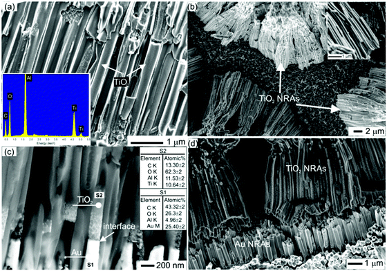
Fig. 1a shows a typical SEM image of the TiO2 NRAs embedded into the AAO membrane with a nominal pore diameter of 200 nm. SEM EDS analysis (inset of Fig. 1a) confirm that the sample consists of Ti and O without any detectable impurities. SEM images (top view) of the free standing TiO2 NRAs after dissolving the AAO membranes are provided in Fig. 1b. The length of the TiO2 NRAs is 15 μm as shown in Fig. 1b. The inset of Fig. 1b shows a close-up of a bundle of TiO2 NRAs clearly indicating the rod-like morphology of the sample. It is clearly shown in Fig. 1c that multisegmented Au/TiO2 NRAs were successfully fabricated. The Au (brighter) and TiO2 (darker) segments are evident by the backscattered electron (BSE) contrast image as shown in Fig. 1c. Additionally, SEM–EDS results in Fig. 1c indicate that the segments consist of Au and TiO2. Most importantly, the interface between Au and TiO2 is flat and sharp as indicated by the arrow in Fig. 1c. Fig. 1d shows the multisegmented Au/TiO2 NRAs after dissolving the AAO membrane. The Au segments have a flat surface and the length of the Au segments in Au/TiO2 is around 1–2 μm as shown in Fig. 1c and d.The separation between the TiO2 and Au/TiO2 NRAs embedded inside the AAO membrane is 356 ± 20 nm as shown in Fig. 1a and c. However, after the AAO support is dissolved, the ends of the TiO2 rods attach to each other due to electrostatic and chemical forces, making it difficult to provide the exact separation distance between them. Careful observation of Fig. 1d reveals that the Au segments are not attached to each other and that the separation between them is 100–150 nm. It is worth mentioning that the optical (plasmonic) properties of Au/TiO2 NRAs depend mainly on separation between Au segments (more details are in the Fig. S3, ESI†).
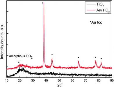
XRD patterns of TiO2 and multisegmented Au/TiO2 NRAs after dissolving the AAO membrane are presented in Fig. 2. The absence of sharp peaks of TiO2 in the XRD pattern of both samples confirms that TiO2 is in amorphous form.14,15 All the diffraction peaks observed in Au/TiO2 NRAs match exactly with the standard data of fcc Au (JCPDS 01-1174). Amorphous TiO2 is favourable in the proposed multisegmented nanostructure because: (1) the work function of amorphous TiO2 is lower than that of its crystalline counterpart due to the large number of oxygen vacancies.14 (2) Amorphous TiO2 is known to have a higher hole transfer rate,16 so fast transportation of holes will increase the separation between charge carriers.
UV-Vis-DR analysis on free standing TiO2 and Au/TiO2 NRAs
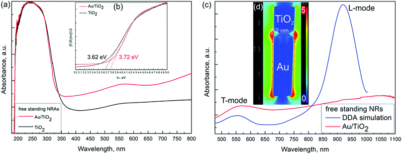
Fig. 3a shows UV-Vis DR spectra for the free standing pristine TiO2 (black line) and Au/TiO2 (red line) NRAs. The black line shows the typical absorption behaviour associated with the TiO2 with strong absorption in the UV-range. It can be observed that the Au/TiO2 sample has a stronger absorption in the whole visible region as compared to the pristine TiO2 sample.In Au/TiO2 NRAs the broad absorption peak around 550 nm is associated with the transverse mode (T-mode) and another hump extends to the near IR region, which can be attributed to the longitudinal mode (L-mode) of Au NRAs. These results prove that the Au/TiO2 NRAs exhibit plasmonic behaviour under visible light irradiation. Such plasmon modes have been predicted with discrete dipole approximation (DDA) simulation.17
The band gaps of TiO2 and Au/TiO2 were determined from Tauc plots and the values are 3.62 and 3.72 eV, respectively, as shown in Fig. 3b. It is well known that amorphous TiO2 has a larger band gap than its crystalline counterparts.18 The observed band gap opening of Au/TiO2 NRAs can be associated with band bending due to the charge transfer between Au and TiO2 segments at the interface.
Fig. 3c compares the UV-Vis DR spectra of Au/TiO2 NRAs for a larger wavelength range with DDA simulation for Au NR with an aspect ratio = 5. It is clearly seen that the T-mode perfectly matches with the simulation results; however the strong peak for the L-mode is missing. The L-mode is significantly affected by (1) change in Au segment lengths, (2) presence of titania segments and (3) the arrangement of Au NRAs, which can result in broadening and intensity loss of the L-mode. We have simulated the variation in the L-mode with the change in the aspect ratio of the Au NRs (Fig. S1, ESI†), presence of the titania segments (Fig. S2, ESI†) and the effect of the arrangement of Au NRAs (Fig. S3, ESI†). The simulation results made us conclude that the broad hump and reduced intensity of the L-mode is due to the abovementioned three factors.
The spatial distribution of the electric field (PRET) across Au/TiO2 NRAs associated with the L-mode was obtained from DDA simulation as shown in Fig. 3d. The PRET enhancement is dominant at the extremities of Au segment, which penetrates into the TiO2 segment for about 2 nm and creates a pathway for hot electron injection in such types of nanostructures (Fig. 3d). It is expected that the high plasmonic electric field and strong coupling between Au and TiO2 at the interface will significantly enhance the plasmon induced charge separation, hot electron injection.2,19
XPS analysis of TiO2 and Au/TiO2
The XPS survey spectra of TiO2 and Au/TiO2 NRAs demonstrated that the main elements on the surface are titanium, oxygen, gold, carbon and sodium (Fig. S4, ESI†). Traces of sodium are the remains of NaOH used to dissolve the AAO membrane. No aluminium signal was detected in the full XPS spectrum (Fig. S4, ESI†) which indicates that the AAO membrane was completely dissolved. Fig. 4a–d shows the high resolution Ti 2p, O 1s, Au 4f and valence band maxima (VBM) spectra for pristine TiO2 and Au/TiO2 NRAs, respectively. The Ti 2p and O 1s core-level spectra of pristine TiO2 and Au/TiO2 NRAs look similar. According to the deconvolution results, the Ti 2p spectrum of TiO2 and Au/TiO2 is dominated by the Ti4+ species. However, the presence of a small amount of reduced Ti3+ was also observed. The Ti 2p spectra for TiO2 have Ti 2p1/2 and Ti 2p3/2 spin–orbital splitting which are located at the binding energies of 464.0 and 458.3 eV, respectively, with a difference of ∼5.7 eV, typical for Ti4+–O.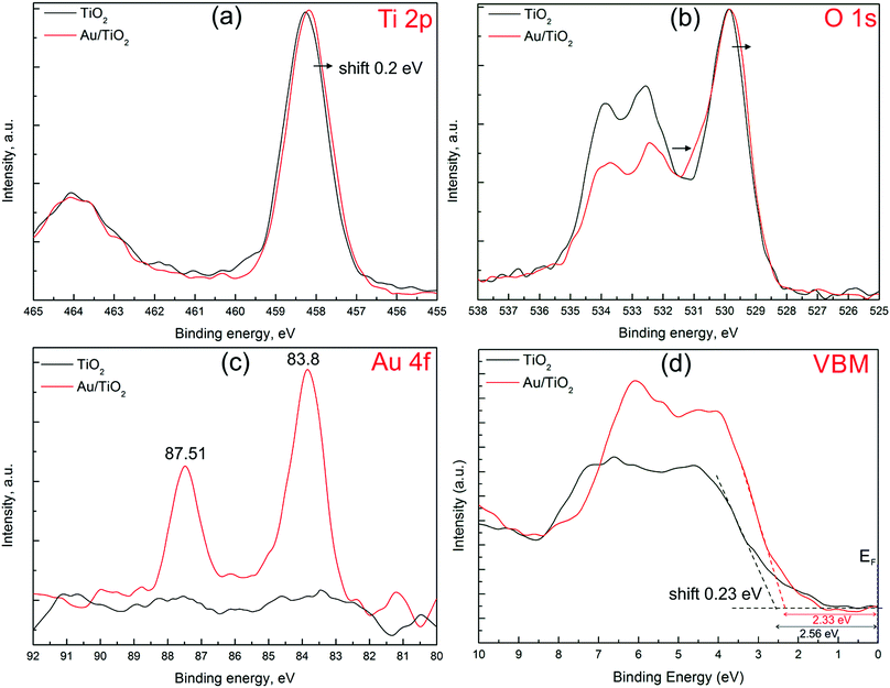 | ||
| Fig. 4 XPS analysis of pure TiO2 (black lines) and Au/TiO2 (red lines): (a) Ti 2p, (b) O 1s, (c) Au 4f spectra and (d) determination of VBM. | ||
The O 1s spectrum (Fig. 4b) is asymmetrical for Au/TiO2, with a tail extending towards higher energies (indicated by an arrow). A similar shape was previously observed for the Au/TiO2 catalyst prepared by deposition–precipitation20 and magnetron sputtering.21 The O 1s spectra were deconvoluted into subpeaks, the major peak is at 529.8 eV which is related with the O2− oxidation state in Ti–oxide. The minor component forming the high-energy tail (shoulder) and appearing at about 0.9–1.5 eV above the major O2− peak (529.9 eV) of the O 1s line was attributed to the presence of subsurface low-coordinated oxygen ions O− (oxygen vacancies).22,23 The relative ratio between the peak at 531.2 eV and the peak at 529.8 eV is lower for the pristine TiO2 sample (0.22) than for the Au/TiO2 sample (0.30) indicating that oxygen vacancies are more abundant in the Au/TiO2 sample. Oxygen vacancies can serve as electrostatic field centers at the interface which results in adhesion between Au and TiO2 and creates networks of Au–O–Ti.24 The peaks at 532.4 and 533.4 eV are assigned to the single and double bonds of C–O and H2O adsorbed on the surface of TiO2 and Au (Fig. 4b).
Fig. 4c shows that Au exists only in the Au/TiO2 sample, indicated by the Au 4f7/2 with a binding energy of 83.8 eV. Fitting the Au 4f7/2 spectrum of the Au/TiO2 NRAs shows the Au segments to be in the purely metallic state.24,25 The observed Au 4f7/2 binding energy is slightly lower than that of the bulk Au at 84.0 eV25 which is attributed to the strong metal–semiconductor interaction. The Au segments in the Au/TiO2 NRAs are negatively charged due to the electron transfer from oxygen vacancies in TiO2 to achieve Fermi level equilibrium, the first indication of formation of the SBH at the interface between Au and TiO2.26
The VBM results of pristine TiO2 and Au/TiO2 samples are shown in Fig. 4d. The VBM position for pristine TiO2 and Au/TiO2 with respect to the Fermi level was found to be 2.56 and 2.33 eV, respectively. Since the zero point of the binding energy scale corresponds to the Fermi level (EF) as shown in Fig. 4d, the position of the VBMs relative to EF show that the TiO2 sample is n-type semiconductor. The above results indicate that the VBM of Au/TiO2 shifts towards a lower binding energy by 0.23 eV compared to pristine TiO2 NRAs. The VBM shift is due to the charge transfer and formation of SBH at the interface between Au and TiO2.5 In detail, when the TiO2 and Au segments are coupled, the difference in work function allows the Au segments to extract and retain electrons from TiO2.27–29 The net charge transfer from TiO2 to Au will continue until the Fermi levels of both materials are aligned.5 This creates an electric field at the interface between Au and TiO2, which is known as SBH (ϕSB). The ϕSB acts like a potential barrier for electrons moving from the Au to the TiO2 segments and it is determined as5,30
| ϕSB = ϕM − χ | (1) |
Photoelectrochemical measurements of TiO2 and Au/TiO2
We further studied the PEC measurements in a three electrode cell arrangement on pristine TiO2 and multisegmented Au/TiO2 NRAs. Upon light excitation, the photocurrent responses of TiO2 (black line) and Au/TiO2 (red line) were obtained as shown in Fig. 5. The TiO2 NRAs exhibit a photocurrent density of 15 μA cm−2, however, the photocurrent density of the multisegmented Au/TiO2 NRAs is around 50 μA cm−2. During the repeated ON/OFF switching, after the first few pulses no significant photocurrent density degradation was observed for pristine TiO2 as well as Au/TiO2 NRAs, which reveals the good reversibility of the process and photostability of the samples. The photocurrent behaviour can be influenced by many factors including the plasmon damping process,35 hot electron generation36 and plasmon induced charge transfer mechanisms.37,38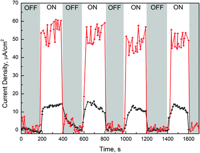 | ||
| Fig. 5 Photoinduced current measurements on pure TiO2 NRAs (black line) and multisegmented Au/TiO2 NRAs (red line) with and without light excitations. | ||
The photocurrent density of Au/TiO2 NRAs is 4 times larger than that of the pristine TiO2, which can be associated with the plasmon-sensitized process via hot electron injection and PRET enhancement from Au to TiO2 segments. Therefore, the synergistic effect of the local PRET enhancement (Fig. 3d) and the hot electron injection significantly increases the electron/hole pair generation in Au/TiO2 NRAs. In addition, the SPR wavelength of Au is above 500 nm (Fig. 3a), therefore the enhancement of the photo-absorption and generation of hot electrons in Au/TiO2 NRAs is in the visible and NIR light ranges. The above-mentioned results of multisegmented Au/TiO2 NRAs can be well understood by the formation of SBH and by taking into account the hot electron transfer model as shown in Fig. 6a. After contacting Au and TiO2 as shown in Fig. 6b, electrons are extracted from TiO2 to the contiguous Au segment in order to maintain the Fermi level equilibrium. The literature value of the work function of Au is 5.31 eV39 and the TiO2 electron affinity is around 4.9–5.1 eV.40 Thus, as a result of the Fermi level equilibrium, a SBH of about 0.23 eV is generated at the Au/TiO2 interface as was observed in the XPS spectra of VBM (Fig. 4d). The hot electrons generated in Au have an energy of around 1–2 eV,41–43 thus ensuring that the hot electrons generated in the SPR process will flow across the SBH and result in a high photocurrent density as shown in Fig. 5. In addition, amorphous TiO2 possesses absorption in the UV light region, and a great amount of electron–hole pairs can be generated in the TiO2 segment under UV-light irradiation, which contributes also as photoelectrons. There are some theoretical and experimental reports on hot electron injection and PRET enhancement between Au and TiO2 nanostructures.35,36,44,45 However, this work is important as it provides both theoretical as well as experimental results on novel immobilized multisegmented Au/TiO2 NRAs to investigate the enhanced photocurrent due to the plasmonic-induced hot electron injection and to explain their potential for future solar-light induced photocatalysis.
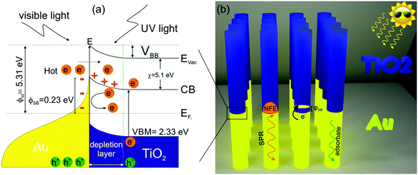 | ||
| Fig. 6 (a) Band diagram of the Au/TiO2 system, the optical process, hot electron injection, generation of SBH at the interface. (b) Schematic image of the free standing multisegmented (Au/TiO2) NRAs. | ||
Conclusions
We have fabricated immobilized multisegmented Au/TiO2 NRAs inside AAO membranes via a template-assisted electrodeposition technique. UV-Vis DR measurements on free standing Au/TiO2 NRAs showed a broad spectrum at 550 nm which is ascribed to the T-mode. It was shown with the simulation results that the intensity of the L-mode was reduced due to three factors namely, (1) size variation of the Au NRs, (2) presence of the TiO2 segment, and (3) hexagonally arranged Au arrays. Taking into consideration these experimental factors, the UV-Vis results are in good correlation with simulation data. The band gap opening for Au/TiO2 NRAs is attributed to the formation of the SBH, which is subsequently related to the charge transfer between Au and TiO2 at the interface. The XPS results showed reduced binding energy for Au 4f7/2 and concurrent increase in the Ti3+–O species, which is considered as direct evidence for charge transfer from oxygen vacancies in TiO2 to Au segments. Detailed XPS analysis on VBM allowed us to determine an SBH of 0.23 ± 0.03 eV between the amorphous TiO2 and the Au interface, which is very close to theoretical literature values. The generation of photoelectrons in Au/TiO2 NRAs is 4× higher than pristine TiO2 NRAs, which is associated with the plasmon-sensitized process via hot electron injection, PRET enhancement from Au to TiO2 segments and charge carriers generated via the UV-light absorption in TiO2. Our study directly probes the SBH and enhanced photoelectron generation in novel plasmonic immobilized multisegmented Au/TiO2 NRAs. Further improvements in photocurrent output can be achieved through the optimization of Au/TiO2 architecture and interface engineering. Such nanostructural Au/TiO2 NRAs have potential applications for efficient solar energy harvesting devices.Conflicts of interest
There are no conflicts to declare.Acknowledgements
The authors acknowledge financial support from the Slovenian Research Agency (research core funding No. P2-0150). M. S. Arshad also acknowledges the help of Irena Abramovič for the electrodeposition of Au/TiO2 NRAs, Dr Gregor Žerjav for help regarding PEC measurements and Tatjana Filipič for help with XPS characterization.References
- Z. Xuming, C. Yu Lim, L. Ru-Shi and T. Din Ping, Rep. Prog. Phys., 2013, 76, 046401 CrossRef PubMed.
- X.-C. Ma, Y. Dai, L. Yu and B.-B. Huang, Light: Sci. Appl., 2016, 5, e16017 CrossRef CAS.
- W. Hou and S. B. Cronin, Adv. Funct. Mater., 2013, 23, 1612–1619 CrossRef CAS.
- M. R. Khan, T. W. Chuan, A. Yousuf, M. N. K. Chowdhury and C. K. Cheng, Catal. Sci. Technol., 2015, 5, 2522–2531 CAS.
- Z. Zhang and J. T. Yates, Chem. Rev., 2012, 112, 5520–5551 CrossRef CAS PubMed.
- K. Horn, Appl. Phys. A: Mater. Sci. Process., 1990, 51, 289–304 CrossRef.
- Y. Gao, Mater. Sci. Eng., R, 2010, 68, 39–87 CrossRef.
- L. Wen, Z. Wang, Y. Mi, R. Xu, S.-H. Yu and Y. Lei, Small, 2015, 11, 3408–3428 CrossRef CAS PubMed.
- Y. J. Hwang, A. Boukai and P. Yang, Nano Lett., 2009, 9, 410–415 CrossRef CAS PubMed.
- L. J. Lauhon, M. S. Gudiksen, D. Wang and C. M. Lieber, Nature, 2002, 420, 57–61 CrossRef CAS PubMed.
- A. W. Maijenburg, E. J. B. Rodijk, M. G. Maas, M. Enculescu, D. H. A. Blank and J. E. ten Elshof, Small, 2011, 7, 2709–2713 CrossRef CAS PubMed.
- Y. Xia, P. Yang, Y. Sun, Y. Wu, B. Mayers, B. Gates, Y. Yin, F. Kim and H. Yan, Adv. Mater., 2003, 15, 353–389 CrossRef CAS.
- S. A. Chambers, T. Droubay, T. C. Kaspar and M. Gutowski, J. Vac. Sci. Technol., B: Microelectron. Nanometer Struct.–Process., Meas., Phenom., 2004, 22, 2205–2215 CrossRef CAS.
- B. Bharti, S. Kumar, H.-N. Lee and R. Kumar, Sci. Rep., 2016, 6, 32355 CrossRef CAS PubMed.
- B. Bharti, S. Kumar and R. Kumar, Appl. Surf. Sci., 2016, 364, 51–60 CrossRef CAS.
- H. H. Pham and L.-W. Wang, Phys. Chem. Chem. Phys., 2015, 17, 541–550 RSC.
- P. K. Jain, X. Huang, I. H. El-Sayed and M. A. El-Sayed, Plasmonics, 2007, 2, 107–118 CrossRef CAS.
- K. Kaur and C. V. Singh, Energy Procedia, 2012, 29, 291–299 CrossRef CAS.
- Y.-C. Yen, J.-A. Chen, S. Ou, Y.-S. Chen and K.-J. Lin, Sci. Rep., 2017, 7, 42524 CrossRef CAS PubMed.
- B. Schumacher, V. Plzak, J. Cai and R. J. Behm, Catal. Lett., 2005, 101, 215–224 CrossRef CAS.
- G. M. Veith, A. R. Lupini and N. J. Dudney, J. Phys. Chem. C, 2009, 113, 269–280 CAS.
- J.-C. Dupin, D. Gonbeau, P. Vinatier and A. Levasseur, Phys. Chem. Chem. Phys., 2000, 2, 1319–1324 RSC.
- H. Liu, W. Yang, Y. Ma, Y. Cao, J. Yao, J. Zhang and T. Hu, Langmuir, 2003, 19, 3001–3005 CrossRef CAS.
- H. Chen, P. Li, N. Umezawa, H. Abe, J. Ye, K. Shiraishi, A. Ohta and S. Miyazaki, J. Phys. Chem. C, 2016, 120, 5549–5556 CAS.
- N. Kruse and S. Chenakin, Appl. Catal., A, 2011, 391, 367–376 CrossRef CAS.
- V. Jovic, W.-T. Chen, D. Sun-Waterhouse, M. G. Blackford, H. Idriss and G. I. N. Waterhouse, J. Catal., 2013, 305, 307–317 CrossRef CAS.
- H. B. Michaelson, J. Appl. Phys., 1977, 48, 4729–4733 CrossRef CAS.
- A. Borodin and M. Reichling, Phys. Chem. Chem. Phys., 2011, 13, 15442–15447 RSC.
- N. T. Khoa, S. W. Kim, D.-H. Yoo, E. J. Kim and S. H. Hahn, Appl. Catal., A, 2014, 469, 159–164 CrossRef CAS.
- R. T. Tung, Appl. Phys. Rev., 2014, 1, 011304 Search PubMed.
- D. Zhang, M. Yang, H. Gao and S. Dong, J. Phys. Chem. C, 2017, 121, 7139–7143 CAS.
- I. Marri and S. Ossicini, Solid State Commun., 2008, 147, 205–207 CrossRef CAS.
- Y. Jiao, A. Hellman, Y. Fang, S. Gao and M. Käll, Sci. Rep., 2015, 5, 11374 CrossRef CAS PubMed.
- E. W. McFarland and J. Tang, Nature, 2003, 421, 616–618 CrossRef CAS PubMed.
- M. L. Brongersma, N. J. Halas and P. Nordlander, Nat. Nanotechnol., 2015, 10, 25–34 CrossRef CAS PubMed.
- A. Manjavacas, J. G. Liu, V. Kulkarni and P. Nordlander, ACS Nano, 2014, 8, 7630–7638 CrossRef CAS PubMed.
- C. Boerigter, U. Aslam and S. Linic, ACS Nano, 2016, 10, 6108–6115 CrossRef CAS PubMed.
- C. Boerigter, R. Campana, M. Morabito and S. Linic, Nat. Commun., 2016, 7, 10545 CrossRef CAS PubMed.
- J. Rumble, CRC Handbook of Chemistry and Physics, Taylor & Francis, 98th edn, 2006 Search PubMed.
- D. O. Scanlon, C. W. Dunnill, J. Buckeridge, S. A. Shevlin, A. J. Logsdail, S. M. Woodley, C. R. A. Catlow, M. J. Powell, R. G. Palgrave, I. P. Parkin, G. W. Watson, T. W. Keal, P. Sherwood, A. Walsh and A. A. Sokol, Nat. Mater., 2013, 12, 798–801 CrossRef CAS PubMed.
- S. M. Sze, J. L. Moll and T. Sugano, Solid-State Electron., 1964, 7, 509–523 CrossRef.
- L. Young Keun, L. Hyosun, L. Changhwan, H. Euyheon and P. Jeong Young, J. Phys.: Condens. Matter, 2016, 28, 254006 CrossRef PubMed.
- J. R. M. Saavedra, A. Asenjo-Garcia and F. J. García de Abajo, ACS Photonics, 2016, 3, 1637–1646 CrossRef CAS.
- S. Linic, P. Christopher and D. B. Ingram, Nat. Mater., 2011, 10, 911–921 CrossRef CAS PubMed.
- M. Wang, M. Ye, J. Iocozzia, C. Lin and Z. Lin, Adv. Sci., 2016, 3, 1600024 CrossRef PubMed.
Footnote |
| † Electronic supplementary information (ESI) available: Fig. S1: (a) The extinction spectra of Au NRs with various AR. (b) Linear relationships between λmax and AR for Au NRs. Fig. S2: The extinction spectra of Au and multisegmented Au/TiO2 NR with the same AR. Fig. S3: (a) Hexagonally arranged 7 NRAs separated by distance (S) with diameter (D). (b) Extinction spectra of a single Au NR and Au NRs in arrays with different separations (S = 15 and 20 nm). NFE of hexagonally arranged Au NRAs with separation of around (c) 15 nm and (d) 20 nm. Fig. S4: XPS survey spectrum of TiO2 and Au/TiO2 NRAs. See DOI: 10.1039/c7tc02633a |
| This journal is © The Royal Society of Chemistry 2017 |

