
A replacement for incandescent bulbs: high-efficiency blue-hazard free organic light-emitting diodes
J. H.
Jou
*a,
H. H.
Yu
a,
F. C.
Tung
 ab,
C. H.
Chiang
a,
Z. K.
He
a and
M. K.
Wei
c
ab,
C. H.
Chiang
a,
Z. K.
He
a and
M. K.
Wei
c
aDepartment of Materials Science and Engineering, National Tsing Hua University, HsinChu 30013, Taiwan. E-mail: jjou@mx.nthu.edu.tw
bMechanical and Mechatronics Systems Research Laboratories, Industrial Technology Research Institute, Hsinchu 31040, Taiwan
cDepartment of Materials Science and Engineering, National Dong Hwa University, Hualien 97401, Taiwan
First published on 12th December 2016
Abstract
A blue-hazard free, healthy light source will become the mainstream of future lighting, wherein higher energy saving is always a must. Although the use of incandescent bulbs is the most friendly electricity-driven lighting measure from the perspectives of the human eye, melatonin generation, artifacts, ecosystems, the environment, and night skies due to their intrinsically low blue emission, they are phasing out because of energy wasting. We hence devise a highly efficient organic light-emitting diode which exhibits a color mimicking that of an incandescent bulb, and a 120 lm W−1 at 100 cd m−2 power efficacy, which is 12 times that of an incandescent bulb or 1000 times that of a candle. This warm sensation giving lighting device is at least 10 times safer from the retinal protection perspective and 4 times better for melatonin secretion, as compared with the cold white counterparts of the compact fluorescent lamp and the light-emitting diode.
Introduction
Numerous medical studies reported that intense blue or white light may cause hazards such as irreversible retinal damage, physiological disorders, and increasing the risk of various cancers.1–3 Stevens et al. revealed electric light at night to be a critical factor explaining the breast cancer burden resulting from the suppression of the oncostatic hormone, melatonin.4–6 Meanwhile, the International Energy Agency reported that the intensive blue emission from white light-emitting diodes (LEDs) may cause damage to the human eye.7,8 Besides the human sphere, the International Dark-Sky Association reported pollution from light-at-night to disrupt the life-sustaining behaviors of nocturnal animals, including birds, amphibians and insects, causing ecosystem disruption.9,10 Moreover, other deleterious effects from short-wavelength lights include dark sky pollution and artifact discoloring in museums, where the blue LED is thought to be the culprit of discoloring the priceless oil paintings by Van Gogh and Cézanne.11Recently, the U.S. Department of Energy also urged the development of a new light quality index to take into account the effect of light on health.12 This implies health to be an issue in the current lighting measures. In order to diminish these blue hazards, there is an urgent need for eco- and human-friendly light sources. With respect to human body, it should be injury-free to retina, psychology and physiology. Moreover, it should also be harmless to animals, insects, the environment, artifacts, and night skies.
Electricity driven lighting sources, both cold-white and warm-white lights, show intensive blue emission. In contrast, incandescent bulbs provide a continuous natural light-style spectrum with low blue emission, the use of which may serve as a physiologically friendly lighting measure.13 Besides, they show the highest color rendering index that ensures color faithfulness as well as visual comfort. In brief, the use of incandescent bulbs is safer than most of the other electricity-driven lighting measures from the health perspective.
Unfortunately, incandescent bulbs are phasing out because of energy wasting. To be specific, its power efficiency is around 10 lm W−1, depending on the applied wattage. Since 2007, many countries have gradually prohibited the use or sale of incandescent bulbs, and proposed to replace them with either energy-efficient light bulbs or solid-state lighting sources.14,15 In addition to energy wasting, there still exist numerous shortcomings in incandescent bulbs, including short lifetime and scorching, etc.
There are reasons regarding why organic light-emitting diodes (OLEDs) are preferred. First of all, OLEDs inherit a high degree of freedom in their chromaticity design, enabling the design and fabrication of lights with high, low or tunable color temperature.16 Besides, OLEDs are plane light sources with numerous overwhelming characteristics, including soft, glare free, flickering free, and fully dimmable, etc. Most importantly, low color temperature OLEDs with high efficiency are obtainable. In 2013, candlelight-style OLED devices with a 1900 K color temperature were presented, proving the feasibility to fabricate a human-friendly light source with a low color temperature.17,18 On the other hand, for the phosphor-converted white LEDs, an intensive blue emission from the blue LED chip is unavoidable to trigger white-light complementary phosphors. Otherwise, the red phosphor, intrinsically low in luminous efficiency, has to be employed to lower the desirable color temperature, which might lead the resultant device to be energy-inefficient.19,20
In this report, we present a highly efficient organic light emitting diode which exhibits a color mimicking that of an incandescent bulb. Its resulting power efficacy is 120 lm W−1 at 100 cd m−2, which is 12 times that of an incandescent bulb and 1000 times that of a candle. Furthermore, it is at least 10 times safer from the retinal protection perspective and 4 times better for melatonin secretion, as compared with the cold-white counterparts of a compact fluorescent lamp and a light emitting diode. By comparing with the incandescent bulb, it is 3 times safer from the retinal protection perspective, and 2 times better for melatonin generation.
Results and discussion
Fig. 1 exhibits the efficacy records of white OLEDs since 1995, compared with those of incandescent bulbs, fluorescent tubes and LED lamps.21 The resultant power efficacy of the low color temperature (CT) blue-hazard free OLEDs fabricated herein has achieved 120 lm W−1 at 100 cd m−2 or 104 lm W−1 at 1000 cd m−2. It is comparable or even higher than some of the current fluorescent tubes and LED lamps, making these low CT, incandescent-style OLEDs potential candidates to replace the warm sensation-giving incandescent bulbs. | ||
| Fig. 1 Efficacy records of white OLEDs since 1995 compared with those of incandescent bulbs, fluorescent tubes and LED lamps. Marked progress has been made for white OLEDs by using efficiency-effective device architectures and light out coupling techniques as well as highly electroluminance active dyes, especially those of electro-phosphorescence. | ||
Table 1 summarizes the electroluminance characteristics of the devices studied, including power efficiency, current efficiency, external quantum efficiency (EQE), operation voltage, Commission Internationale de l'Eclairage (CIE) coordinates, and maximum luminance. To attain the high power efficiency, three major approaches have been attempted, including the use of high efficiency materials, efficiency-effective device architectures, and a light extraction technique.
| Device | Red dopant concentration (wt%) | EML TCTA![[thin space (1/6-em)]](https://www.rsc.org/images/entities/char_2009.gif) :TPBi :TPBi |
V° (V) | PE (lm W−1) | CE (cd A−1) | EQE (%) | CIE coordinates | CT (K) | Maximum luminance (cd m−2) |
|---|---|---|---|---|---|---|---|---|---|
| @100/1000 cd m−2 | |||||||||
| a Device with a microlens thin film array. | |||||||||
| I | 5 | 10:0 |
2.9/3.6 | 28.1/23.9 | 26.3/27.5 | 13.0/13.0 | (0.58, 0.42)/(0.58, 0.42) | 1650/1670 | 15900 |
| II | 5 | 0:10 |
2.5/2.9 | 77.0/63.4 | 62.1/58.7 | 20.8/19.7 | (0.51, 0.49)/(0.50, 0.49) | —/— | 74980 |
| III | 5 | 7:3 |
2.7/3.0 | 55.7/47.4 | 47.9/45.0 | 18.2/17.2 | (0.53, 0.46)/(0.53, 0.46) | 2280/2280 | 71500 |
| IV | 5 | 5:5 |
2.6/2.9 | 57.6/48.9 | 48.0/45.4 | 18.7/17.7 | (0.54, 0.46)/(0.54, 0.46) | 2210/2230 | 82600 |
| V | 5 | 3:7 |
2.6/2.9 | 59.8/52.3 | 48.8/47.7 | 18.7/18.4 | (0.53, 0.46)/(0.53, 0.47) | 2260/2280 | 86160 |
| VI | 5 | 2:8 |
2.5/2.8 | 69.4/57.9 | 55.9/51.8 | 20.5/19.0 | (0.52, 0.47)/(0.52, 0.47) | 2400/2420 | 95680 |
| VII | 5 | 1:9 |
2.6/2.9 | 58.2/47.5 | 47.4/44.2 | 17.7/16.5 | (0.53, 0.47)/(0.53, 0.47) | 2330/2320 | 70700 |
| VIII | 2.5 | 2:8 |
2.6/2.9 | 85.1/73.8 | 69.1/68.1 | 22.1/22.4 | (0.51, 0.49)/(0.51, 0.49) | 2610/2610 | 91030 |
| VIII | 2.5 |
2![[thin space (1/6-em)]](https://www.rsc.org/images/entities/b_char_2009.gif) :8 :8
|
2.6/2.8 | 120.0/103.8 | 96.6/93.3 | 30.7/30.6 | (0.51, 0.49)/(0.51, 0.50) | 2650/2670 |
126600
|
Fig. 2a shows the schematic diagram of the energy levels of Device I, which comprises a single EML-1 with an orange-red emitter (Ir(2-phq)3) doped in the TCTA host. Fig. 2b shows the schematic diagram of the energy levels of Device II, which comprises a single EML-2 with green (Ir(ppy)3) and yellow (PO-01) emitters doped in the TPBi host.
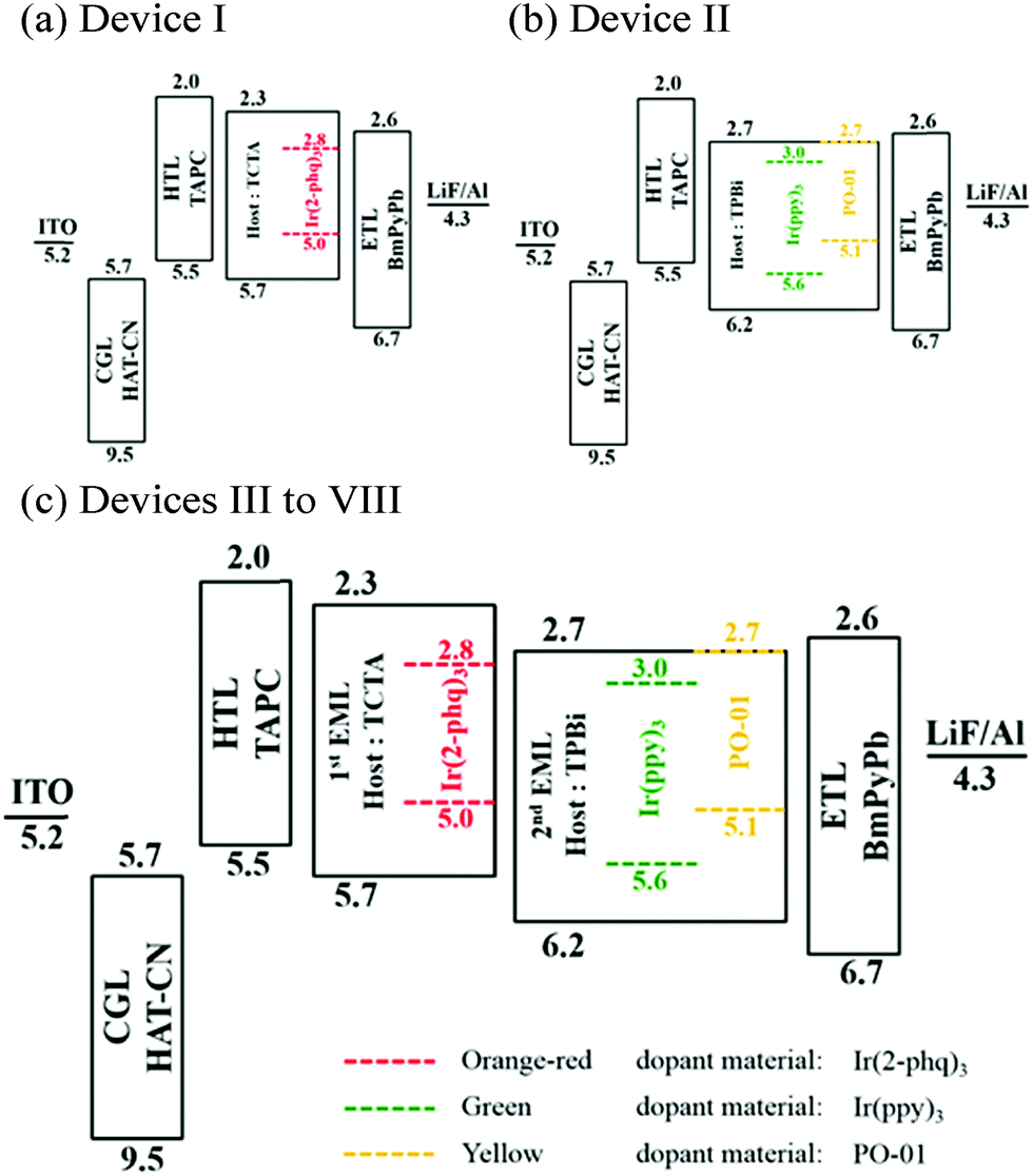 | ||
| Fig. 2 Schematic diagrams of the energy levels of the OLED devices containing (a) a single emission layer (EML) with an orange-red emitter (Device I), (b) a single EML with a green and a yellow emitter (Device II), and (c) three emitters dispersed in two EMLs (Devices III to VIII). | ||
From the material perspective, we had used three high-efficiency phosphorescent materials, i.e. orange-red emitter tris(2-phenylquinoline) iridium(III) Ir(2-phq)3, green tris(2-phenylpyridine) iridium(III) (Ir(ppy)3), and yellow iridium(III) bis(4-phenylthieno[3,2-c]pyridinato-N,C2′)acetylacetonate (PO-01), whose respective quantum yields are 75%, 40%, and 48%.22 In addition, we used an electron transporting material, 1,3-bis(3,5-dipyrid-3-yl-phenyl)benzene (BmPyPB), that exhibits a high electron mobility, 10−4 cm2 V−1 s−1,23,24 to facilitate the injection of the minor carrier, electron. The balance between the injection of the electron and that of the major carrier, hole, serves as one critical key toward high device efficiency.
From the device architecture perspective, the efficiency favorable factors that were taken into account in the device design include (i) an energy trap to facilitate the injection of the minor carriers,25–28 (ii) an effective host-to-guest energy transfer system,29–31 (iii) a step-wise emissive layer structure to minimize barriers for the injecting hole and the electron,32 and (iv) an effective carrier confinement.33–37
First, as seen in the device structures of Devices III to VIII (Fig. 2c), the resultant device was designed with a respective −0.1 eV and −0.4 eV electron-injection-trap with respect to the LUMO of the ETL (BmPyPb) for the 1,3,5-tris(N-phenyl-benzimidazol-2-yl)benzene (TPBi) host and the Ir(ppy)3 co-host. These electron traps would favor the capture of electrons by the host and the co-host to counterbalance the injection of holes. These would in turn favor the mechanisms of efficiency-effective host-to-guest and co-host-to-guest energy transfer. Second, either the host, TPBi, or the co-host, Ir(ppy)3, can effectively transfer its energy to the yellow dye in the second EML, according to a previous study.38 Indeed, the energy transfer from both the host and the co-host to the yellow dye seem to be complete by evidencing no emission arising from the host and the co-host in the short wavelength region, as seen in the resultant EL spectra of the devices (Fig. 3a). These complete and effective energy transfers help achieve a high device efficiency.
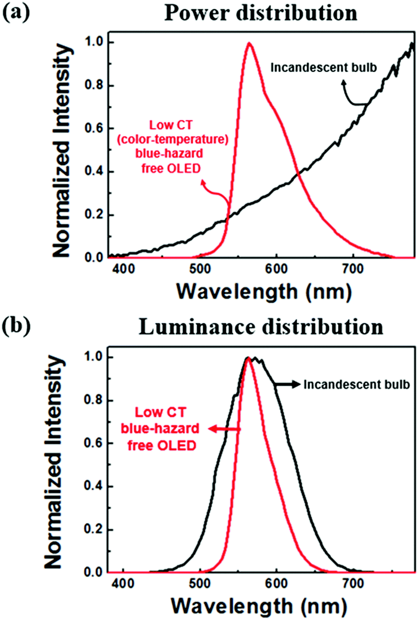 | ||
| Fig. 3 Comparison of the (a) spectral power and (b) luminosity distributions of the low color temperature (CT) blue-hazard free OLED with the incandescent bulb. Although the power spectra of the two light sources are quite dissimilar, they look almost the same from the viewpoint of the human eye. The high-efficiency blue-hazard free OLED shows a 52% similarity with the incandescent bulb as compared to their luminance distributions that are obtained by convoluting the power spectra with the luminosity function. | ||
Third, the stepwise device structure (Fig. 2c) helps break the entire injection barriers into smaller segments. The operation voltage of the device can hence be reduced effectively, which would in turn yield higher device efficiency at a low operation voltage. Moreover, the entering electrons and holes can be effectively confined and thus recombine within the desired emission layers owing to the presence of two neighboring electron transporting and hole transporting layers, the former of which possesses an effective hole-blocking barrier and the latter possesses an effective electron-blocking barrier. Specifically, there exists a barrier of 0.3 eV to prevent electrons leaving from EML-1 to the HTL. On the other hand, there exists a barrier of 0.5 eV to prevent holes leaving from EML-2 to the ETL. As a result, high efficiency could have resulted since no or little carriers would leak away from the desired emissive layers.
From the light out-coupling perspective, the efficiency as a micro-lens thin film array was adhered to the backside of the ITO glass that was increased from 85 lm W−1 to 120 lm W−1, an increment of 41%. The micro-lens-array films were fabricated using a series of photolithography, thermal reflow, polydimethylsiloxane molding and UV forming techniques. After 8 steps of processing, a convex micro-lens array film was fabricated by peeling off the film and the mold. Details regarding how to fabricate the micro-lens array films are given in the Experimental section.
From the health perspective, incandescent light from tungsten bulbs is so far the safest among all the electricity-driven lighting measures that have acceptable light quality. That is because it emits comparatively the least short wavelength emissions like violet and blue, and hence possesses the least threat on retinal damage or melatonin suppression. Meanwhile, its totally continuous and smooth spectrum yields lighting with a near perfect light quality, in terms of either the color rendering index (CRI) or the spectrum resemblance index (SRI).39 These observations explain why incandescent bulbs were most welcome in general illumination if not for the sake of energy wasting and why we attempt to develop high-efficiency incandescent-style OLEDs.
The presented incandescent-style OLED shows a color temperature of 2650 K, while it is 2500 K for the studied incandescent bulb. Table 2 shows the comparison of the characteristics of the incandescent-style OLED in terms of color temperature, the maximum permissible exposure-limit (MPE) of retina (s), and melatonin suppression sensitivity (MSS) relative to those of a 480 nm blue light, against those of the compact fluorescent lamp (CFL), the incandescent bulb, and the cold-white LED bulb.
| Light source/CT (K) | Exposure limit (s) @ (lx) | MLT suppression sensitivitya (%) | |
|---|---|---|---|
| 100 | 500 | ||
| a With respect to the suppression sensitivity of 480 nm blue light on melatonin (MLT) generation at night. | |||
| Blue-hazard free OLED/2650 | 3480 | 695 | 4.8 |
| Incandescent bulb/2500 | 1047 | 210 | 11.4 |
| Cold-white CFL/5920 | 316 | 63 | 29 |
| Cold-white LED/5500 | 343 | 67 | 20 |
From the human-eye protection perspective, the incandescent-style OLED permits an exposure limit of 3480 seconds (58 minutes) before causing permanent damage to the retina. It is 10 times safer than those of the cold-white CFL (5920 K) and cold-white LED (5520 K), whose MPEs are 316 (5 minutes) and 343 seconds (6 minutes), respectively. It is 3 times safer than that of the incandescent bulb (2500 K), whose MPE is 1047 seconds (18 minutes). The above results are based at an illuminance of 100 lx, the average intensity for residential illumination. At 500 lx, the typical lighting intensity in office, all the above MPEs are 5 times shorter, indicating that the equivalent retinal damage occurs 5 times faster. More specifically, the permissible exposure time would become 695 seconds (11 minutes) for the incandescent-style OLED, 210 seconds (3.5 minutes) for the incandescent bulb, 63 seconds (1 minute) for the cold-white CFL, and 67 seconds (1 minute) for the cold-white LED, respectively.
From the melatonin generation perspective, the melatonin suppression sensitivity (MSS) of the incandescent-style OLED is only 4.8% to that of the 480 nm blue light, which is 2, 5 and 4 times safer than the incandescent bulb (2500 K), the cold-white CFL (5920 K) and cold-white LED (5500 K).
As mentioned earlier, incandescent light is well known for its ultimately smooth and continuous spectrum with the warm and soft sensation-giving glow. To mimic such an incandescence emission, multiple incandescent light complementary dyes, mainly red, yellow and green, were doped into two different emissive layers in the OLED devices, as shown in Fig. 4. Among them, Device VIII that shows the highest efficiency exhibits a color temperature of 2650 K with CIE coordinates of (0.51, 0.49), as shown in Table 1. The resultant color, however, somewhat deviates away from the locus of blackbody radiation and is slightly different from that of the incandescent bulb.
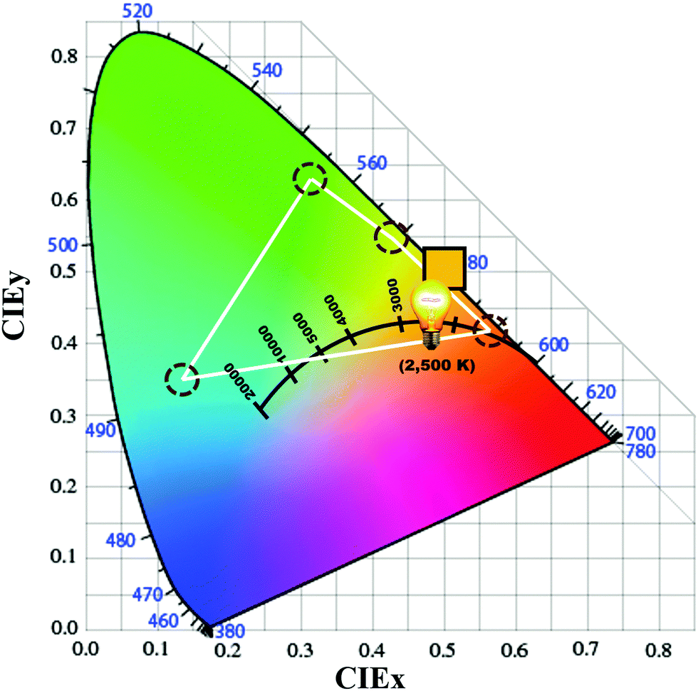 | ||
| Fig. 4 The employment of multiple low color temperature blackbody radiation complementary organic emitters can generate blue-hazard free lights for illumination. The resultant color temperature of one blue-hazard free OLED device is 2650 K, which exhibits a color mimicking that of an incandescent bulb at 2500 K. | ||
Fig. 3a shows the power spectrum of the high-efficiency blue-hazard free OLED device with a 2650 K color temperature compared with that of the incandescent bulb at 2500 K. As shown, the emission of the incandescent bulb is the strongest in the long wavelength region, and decreases monotonically toward the violet emission region. Fig. 3b shows the luminance spectrum of the high-efficiency blue-hazard free OLED and the incandescent bulb. The figure shows that the two lights have a 52% similarity in their luminance spectra, with the major emission peaking at around 560 nm, where the luminance spectra were obtained by convoluting the experimentally determined power spectra with the luminosity function. Although the power spectra of the two light sources are quite dissimilar, they look almost the same from the viewpoint of the human eye. Besides, by using a sky-blue emitter, i.e. FIrpic, a predictable improvement in the SRI can be achieved.
Conclusions
We have demonstrated in this study a high efficiency incandescent-style organic light-emitting diode with a power efficacy of 120 lm W−1, which is 12 times that of an incandescent bulb or 1000 times that of a candle. The high efficiency may be attributed to the employment of three efficiency-effective approaches, namely the use of high efficiency and high mobility materials, efficiency-effective device architectures, and a light extraction technique. Notably, it is at least 10 times safer from the retinal protection perspective and 4 times better for melatonin secretion, as compared with the cold-white counterparts of CFLs, LEDs and OLEDs, which may serve as a human-friendly and energy-saving lighting measure.Experimental
Theoretical
The maximum admissible retinal exposure limit (t) with a unit of second (s) was originally reported by the International Electrotechnical Commission (IEC). The value of “t” can be determined according to the IEC 62471 standard,40 as shown below: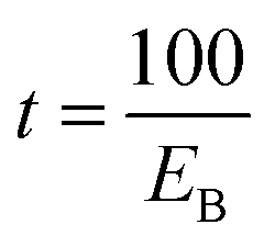 | (1) |
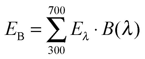 | (2) |
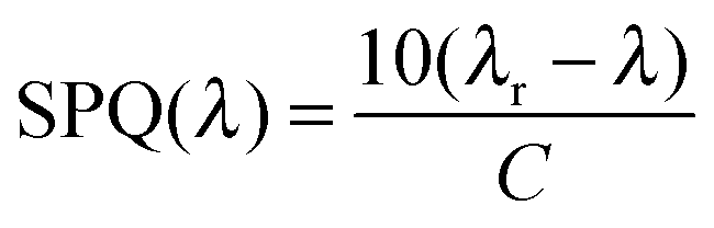
The action spectrum of melatonin suppression per photon quanta (SPQ) was first presented by Jou in the US patent.41 The resultant formula can be expressed as follows:
 | (3) |
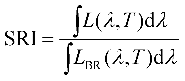
The light quality of given light can be quantified by the nature light spectrum resemblance index, SRI, according to Jou et al.39 The SRI, which is based on a direct comparison of the luminance spectrum of a given light source with its blackbody-radiation counterpart at the same color temperature, can be defined as follows:
 | (4) |
Device fabrication
Fig. 2 shows the structures of the studied OLED devices, which were fabricated via sequential thermal evaporation for both the organic and inorganic materials. Devices I to VIII consisted of a 125 nm indium tin oxide (ITO) anode layer, a 5 nm 1,4,5,8,9,11-hexaazatriphenylene-hexacarbonitrile (HAT-CN) hole injection layer (HIL), a 35 nm di-[4-(N,N-ditolylamino)-phenyl]cyclohexane (TAPC) as a hole transport layer (HTL), a 15 nm single or double emissive-layer (EML) doped with long and short wavelength emitters, a 45 nm 1,3-bis(3,5-dipyrid-3-yl-phenyl)benzene (BmPyPB) as an electron transport layer (ETL), a 1 nm lithium fluoride (LiF) layer, and a 100 nm aluminium (Al) cathode layer. EML-1 comprised a 4,4′,4′′-tri(N-carbazolyl)triphenylamine (TCTA) host doped with a 2.5 wt% or 5 wt% Ir(2-phq)3 orange-red emitter. EML-2 consisted of a 1,3,5-tris(N-phenyl-benzimidazol-2-yl)benzene (TPBi) host doped with a 10 wt% tris(2-phenylpyridine) iridium(III) (Ir(ppy)3) green emitter and a 5 wt% PO-01 yellow emitter. The thickness ratios of EML-1 and EML-2 in Devices III to VIII were 7:3, 5:5, 3:7, 2:8, and 1:9, respectively.
Device measurement
The luminance, CIE chromaticity coordinates, and electroluminescence spectrum of the resultant devices were measured by using a Photo Research PR-655 spectrum. A Keithley 2400 electrometer, together with a Minolta CS-100 luminance meter, was used to measure the current–voltage (I–V) characteristics. The emission area of the devices was 9 mm2, and only the luminance in the forward direction was measured.Micro-lens fabrication
First, a 4 inch (100 mm) silicon wafer after the standard RCA treatment was used as a substrate. Second, an AZ P4620 photoresist (from Clariant K K Technology Production Dept.) was spun on the wafer and soft baked at 90 °C for 7 minutes. Third, a photomask having a regular array of square chrome patterns, having an edge length and a gap distance of 21.2 and 2.5 mm, respectively, was put on the photoresist layer, followed by exposing UV light for 550 mJ cm−2. Fourth, a regular array of photoresist plates with a thickness of 15 μm was formed after the development of the photoresist layer. Fifth, the specimen was kept in an oven and thermally reflowed at 220 °C for 44 hours. Thus, a convex micro-lens-array template was formed. Sixth, liquid polydimethylsiloxane (PDMS) (trademark Sylgard 184A) mixed with its hardener (trademark Sylgard 184B) was poured on the wafer and kept in an oven to be thermally cured at 60 °C for 4 hours. Seventh, the PDMS mold with a concave micro-lens-array on the surface was released by peeling off the wafer and the mold. Eighth, a UV-curable polymethylmethacrylate (PMMA)/polyurethane (PU) copolymer was coated between the mold and a flexible polyethylene terephthalate (PET) film, followed by exposing UV light for 2 J cm−2. Finally, a convex micro-lens array film was fabricated by peeling off the film and the mold. Fig. 5 shows the fabrication scheme of the micro-lens.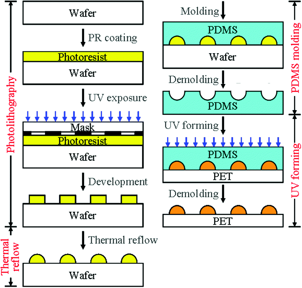 | ||
| Fig. 5 The fabrication scheme of the micro-lens. | ||
Acknowledgements
The authors would like to acknowledge the support from the Energy Fund of the Ministry of Economics Affairs and the Ministry of Science and Technology, Taiwan. This work was financially supported in part by Grants MEA 104-EC-17-A-07-S3-012, MOST 104-2119-M-007-012, and MOST 103-2923-E-007-003-MY3.Notes and references
- S. M. Pauley, Med. Hypotheses, 2004, 63, 588–596 CrossRef PubMed.
- P. R. Mills, S. C. Tomkins and L. J. Schlangen, J. Circadian Rhythms, 2007, 5, 1–9 CrossRef PubMed.
- M. Sato, T. Sakaguchi and T. Morita, Biol. Rhythm. Res., 2005, 36, 287–292 CrossRef CAS.
- R. G. Stevens, G. C. Brainard, D. E. Blask, S. W. Lockley and M. E. Motta, Ca-Cancer J. Clin., 2014, 64(3), 207–218 CrossRef PubMed.
- S. Davis, D. K. Mirick and R. G. Stevens, J. Natl. Cancer Inst., 2001, 93, 1557–1562 CrossRef CAS PubMed.
- I. Kloog, A. Haim, R. G. Stevens, M. Barchanade and B. A. Portnov, Chronobiol. Int., 2008, 25, 65–81 CrossRef PubMed.
- Solid State Lighting Annex: Potential Health Issue of SSL, Final report to International Energy Agency, http://ssl.iea-4e.org/files/otherfiles/0000/0072/IEA_4E_SSL_Annex_Health_Aspects_Study_final.pdf.
- Do Environmentally Friendly LED Lights Cause Blindness, Daily Mail, http://www.dailymail.co.uk/health/article-2324325/Do-environmentally-friendly-LED-lights-cause-BLINDNESS.html.
- Light Pollution Effects on Wildlife and Ecosystem, International Dark-Sky Association, http://darksky.org/light-pollution/wildlife/.
- Dark-Sky says boo to blue light, LEDs Magazine, http://www.ledsmagazine.com/articles/2009/10/dark-sky-says-boo-to-blue-light.html.
- L. Monico, K. Janssens, C. Miliani, G. Van der Sneickt, B. G. Brunetti, M. C. Guidi, M. Radpont and M. Cotte, Anal. Chem., 2013, 124, 272–282 Search PubMed.
- Solid-State Lighting Research and Development: Multi-Year Program Plan; Office of Energy Efficiency and Renewable Energy, the U.S. Department of Energy, http://apps1.eere.energy.gov/buildings/publications/pdfs/ssl/ssl_mypp2014_web.pdf.
- J. H. Jou, K. Y. Chou, F. C. Yang, C. H. Hsieh, S. Kumar, A. Agrawal, S. Z. Chen, T. H. Li and H. H. Yu, Adv. Opt. Mater., 2015, 3(1), 95–102 CrossRef CAS.
- Member States approve the phasing-out of incandescent bulbs by 2012, European Union Commission, http://europa.eu/rapid/press-release_IP-08-1909_en.htm?locale=en.
- Phasing out incandescent bulbs in the EU – Technical briefing, European Union Commision, http://ec.europa.eu/energy/en/topics/energy-efficiency.
- J. H. Jou, M. H. Wu, S. M. Shen, H. C. Wang, S. Z. Chen, S. H. Chen, C. R. Lin and Y. L. Hsieh, Appl. Phys. Lett., 2009, 95, 013307 CrossRef.
- J. H. Jou, C. Y. Hsieh, J. R. Tseng, S. H. Peng, Y. C. Jou, J. H. Hong, S. M. Shen, M. C. Tang, P. C. Chen and C. H. Lin, Adv. Funct. Mater., 2013, 23, 2750–2757 CrossRef CAS.
- J. H. Jou, C. Y. Hsieh, P. W. Chen, S. Kumar and J. H. Hong, J. Photonics Energy, 2014, 4, 43598 CrossRef.
- J. K. Sheu, S. J. Chang, C. H. Kuo, Y. K. Su, L. W. Wu, Y. C. Lin, W. C. Lai, J. M. Tsai, G. C. Chi and R. K. Wu, IEEE Photonics Technol. Lett., 2003, 15(1), 18–20 CrossRef.
- R. M. Mach, G. Mueller, M. R. Krames, H. A. Höppe, F. Stadler, W. Schnick, T. Juestel and P. Schmidt, Phys. Status Solidi A, 2005, 202(9), 1727–1732 CrossRef.
- (a) J. Kido, et al. , Science, 1995, 267, 1332 CrossRef CAS PubMed; (b) Y. D. Jim, et al. , Chem. Phys. Lett., 2000, 325, 251 CrossRef; (c) Y. T. Tao, et al. , Appl. Phys. Lett., 2001, 79, 25 Search PubMed; (d) J. H. Jou, et al. , Appl. Phys. Lett., 2002, 80, 15 Search PubMed; (e) Y. T. Tao, et al. , Appl. Phys. Lett., 2002, 81, 24 Search PubMed; (f) M. E. Thompson, et al. , New J. Chem., 2002, 26, 1171 RSC; (g) G. Cheng, et al. , Appl. Phys. Lett., 2003, 82, 24 Search PubMed; (h) J. H. Jou, et al. , Appl. Phys. Lett., 2006, 88, 193501 CrossRef; (i) J. H. Jou, et al. , Org. Electron., 2006, 7, 8 CrossRef CAS; (j) J. H. Jou, et al. , Org. Electron., 2007, 8, 29 CrossRef CAS; (k) J. H. Jou, et al. , Org. Electron., 2007, 8, 735 CrossRef CAS; (l) C. S. Lee, et al. , Appl. Phys. Lett., 2007, 91, 023503 CrossRef; (m) C. S. Lee, et al. , Appl. Phys. Lett., 2007, 90, 203510 CrossRef; (n) J. H. Jou, et al. , Adv. Funct. Mater., 2008, 18, 121 CrossRef CAS; (o) S. R. Forrest, et al. , Adv. Mater., 2002, 14, 15 Search PubMed; (p) M. E. Thompson, et al. , Org. Electron., 2003, 4, 77 CrossRef; (q) R. F. Service, Science, 2005, 310, 1762 CrossRef CAS PubMed; (r) S. Tokito, et al. , Curr. Appl. Phys., 2005, 5, 331 CrossRef; (s) S. R. Forrest, et al. , Nature, 2006, 440, 13 CrossRef; (t) S. R. Forrest, et al. , Nat. Photonics, 2008, 2, 483 CrossRef; (u) J. Kido, et al. , Adv. Mater., 2008, 20, 4189 Search PubMed; (v) S. Reineke, et al. , Nature, 2009, 459, 14 CrossRef PubMed; (w) J. Kido, et al. , Adv. Mater., 2010, 22, 5003 CrossRef PubMed; (x) D. Ma, et al. , Adv. Mater., 2010, 22, 5370 CrossRef PubMed; (y) Y. Wang, et al. , J. Mater. Chem., 2011, 21, 3551 RSC; (z) T. Han, et al. , Nat. Photonics, 2012, 6, 105 CrossRef CAS; (a a) T. Komoda, et al. , J. Photopolym. Sci. Technol., 2012, 25, 321 CrossRef CAS; (a b) H. Tsuji, et al. , J. Photopolym. Sci. Technol., 2013, 26, 415 CrossRef CAS; (a c) J. Li, et al. , Adv. Mater., 2013, 25, 2573 CrossRef PubMed; (a d) J. S. Chen, et al. , Adv. Mater., 2014, 26, 1617 CrossRef PubMed; (a e) J. Kido, et al. , Nat. Commun., 2014, 1 Search PubMed; (a f) H. W. Lin, et al. , Org. Electron., 2014, 15, 517 CrossRef; (a g) K. T. Wong, et al. , Adv. Electron. Mater., 2015, 2, 1500241 Search PubMed; (a h) C. W. Tang, et al. , Org. Electron., 2016, 32, 54 CrossRef; (a i) Z. Y. Ge, et al. , Nanotechnol., 2016, 27, 124001 CrossRef PubMed.
- J. H. Jou, Y. X. Lin, S. H. Peng, C. J. Li, Y. M. Yang, C. L. Chin, J. J. Shyue, S. S. Sun, M. Lee, C. T. Chen, M. C. Liu, C. C. Chen, G. Y. Chen, J. H. Wu, C. H. Li, C. F. Sung, M. J. Lee and J. P. Hu, Adv. Funct. Mater., 2014, 24, 555–562 CrossRef CAS.
- J. H. Jou, S. Kumar, C. C. An, M. Singh, H. H. Yu, C. Y. Hsieh, Y. X. Lin, C. F. Sung and C. W. Wang, Opt. Express, 2015, 23, A576 CrossRef PubMed.
- J. H. Jou, S. Kumar, A. Agrawal, T. H. Li and S. Sahoo, J. Mater. Chem. C, 2015, 3, 2974 RSC.
- M. Gross, D. C. Muller, H. G. Nothofer, U. Scherf, D. Neher, C. Brauchle and K. Meerholz, Nature, 2000, 405, 661–665 CrossRef CAS PubMed.
- J. H. Lee, P. S. Wang, H. D. Park, C. I. Wu and J. J. Kim, Org. Electron., 2011, 12, 1763–1767 CrossRef CAS.
- M. Pfeiffer, K. Leo, X. Zhou, J. S. Huang, M. Hofmann, A. Werner and J. Blochwitz Nimoth, Org. Electron., 2003, 4, 89–103 CrossRef CAS.
- H. Yanagi, M. Kikuchi, K. B. Kim, H. Hiramatsu, T. Kamiya, M. Hirano and H. Hosono, Org. Electron., 2008, 9, 890–894 CrossRef CAS.
- S. J. Yeh, M. F. Wu, C. T. Chen, Y. H. Song, Y. Chi, M. H. Ho, S. F. Hsu and C. H. Chen, Adv. Mater., 2005, 17, 285–289 CrossRef CAS.
- J. J. Lin, W. S. Liao, H. J. Huang, F. I. Wu and C. H. Cheng, Adv. Funct. Mater., 2008, 18, 485–491 CrossRef CAS.
- J. H. Jou, M. F. Hsu, W. B. Wang, C. L. Chin, Y. C. Chung, C. T. Chen, J. J. Shyue, S. M. Shen, M. H. Wu, W. C. Chang, C. P. Liu, S. Z. Chen and H. Y. Chen, Chem. Mater., 2009, 21, 2565–2567 CrossRef CAS.
- J. H. Jou, P. H. Wu, C. H. Lin, M. H. Wu, Y. C. Chou, H. C. Wang and S. M. Shen, J. Mater. Chem., 2010, 20, 8464–8466 RSC.
- V. I. Adamovich, S. R. Cordero, P. I. Djurovich, A. Tamayo, M. E. Thompson, B. W. D'Andrade and S. R. Forrest, Org. Electron., 2003, 4, 77–87 CrossRef CAS.
- W. Y. Hung, Z. W. Chen, H. W. You, F. C. Fan, H. F. Chen and K. T. Wong, Org. Electron., 2011, 12, 575–581 CrossRef CAS.
- S. J. Su, E. Gonmori, H. Sasabe and J. Kido, Adv. Mater., 2008, 20, 4189–4194 CAS.
- D. Tanaka, T. Takeda, T. Chiba, S. Watanabe and J. Kido, Chem. Lett., 2007, 36, 262–263 CrossRef CAS.
- Q. S. Zhang, T. Komino, S. P. Huang, S. Matsunami, K. Goushi and C. Adachi, Adv. Funct. Mater., 2012, 22, 2327–2336 CrossRef CAS.
- J. H. Jou, H. H. Yu, Y. X. Lin, J. R. Tseng, S. H. Peng, Y. C. Jou, C. H. Lin, S. M. Shen, C. Y. Hsieh, M. K. Wei, D. H. Lin, C. C. Wang, C. C. Chen, F. C. Tung, S. H. Chen and Y. S. Wang, J. Mater. Chem. C, 2013, 1, 5110–5115 RSC.
- J. H. Jou, K. Y. Chou, F. C. Yang, A. Agrawal, S. Z. Chen, J. R. Tseng, C. C. Lin, P. W. Chen, K. T. Wong and Y. Chi, Appl. Phys. Lett., 2014, 104, 203304 CrossRef.
- IEC Standard, 62471, 2006.
- J.-H. Jou, US Pat., 8812242, 2011 Search PubMed.
| This journal is © The Royal Society of Chemistry 2017 |