
 Open Access Article
 This Open Access Article is licensed under a
 Creative Commons Attribution 3.0 Unported Licence
Molecularly imprinted polymer based extended-gate field-effect transistor chemosensors for phenylalanine enantioselective sensing†
Z.
Iskierko
a,
A.
Checinska
b,
P. S.
Sharma
*a,
K.
Golebiewska
a,
K.
Noworyta
*a,
P.
Borowicz
a,
K.
Fronc
c,
V.
Bandi
d,
F.
D'Souza
*d and
W.
Kutner
*ae
aInstitute of Physical Chemistry, Polish Academy of Sciences (IPC PAS), Kasprzaka 44/52, 01-224 Warsaw, Poland. E-mail: psharma@ichf.edu.pl; knoworyta@ichf.edu.pl; wkutner@ichf.edu.pl
bFaculty of Chemistry, Warsaw University of Technology, Noakowskiego 3, 00-664, Warsaw, Poland
cInstitute of Physics of the Polish Academy of Sciences, 32/46 Al. Lotników, 02-668 Warsaw, Poland
dDepartment of Chemistry, University of North Texas, Denton, TX 76203-5017, USA. E-mail: francis.dsouza@unt.edu
eFaculty of Mathematics and Natural Sciences, School of Sciences, Cardinal Stefan Wyszynski University in Warsaw, Wóycickiego 1/3, 01-815 Warsaw, Poland
First published on 15th December 2016
Abstract
Chemosensing systems were devised for the enantioselective determination of D- and L-phenylalanine (D- and L-Phe). As recognition units of these systems, molecularly imprinted polymers (MIPs) were designed, guided by DFT calculations, and then synthesized. For the preparation of these MIPs, carboxy derivatized bis(bithiophene) was used as the functional monomer. Both templated and template-extracted MIP films as well as non-imprinted polymer (NIP) films were characterized by IR spectroscopy to prove Phe templation, and then extraction. Extended-gate field-effect transistors (EG-FETs) served as transducers. The EG-FET gates were coated with D- or (L-Phe)-templated MIP films, by electropolymerization, to result in complete chemosensors. These chemosensors rapidly and selectively responded to D- and L-Phe enantiomer analytes. They readily discriminated between a homologous series of analytes differing by a single atom as well as pairs of enantiomers differing in their three-dimensional structures. Linear dynamic concentration ranges for D- and L-Phe extended from 13 to 100 μM. For both Phe enantiomers, the limit of detection was 13 μM. The enantioselectivity factor was ∼2.3 for both chemosensors.
Introduction
Sensing and separating chiral compounds is very important. Most biological compounds and several pharmaceuticals are chiral.1 Chiral drugs differ in their pharmacokinetic and pharmacodynamic properties.2 In many examples, one enantiomer shows the desired effect (like healing properties) while the effect of the other is not desired, e.g., toxicity. For instance, L-DOPA, used in the treatment of Parkinson's disease, has the D-DOPA enantiomer, which is responsible for the deficiency of white blood cells and, therefore, susceptibility to infections. Similarly, L-methotrexate is better absorbed in the gastrointestinal tract than D-methotrexate, and D-propranolol is more extensively bound to proteins than L-propranolol.2 Therefore, there is a high demand for the selective recognition of these enantiomers and, thus, separation.Until now, high-performance liquid chromatography (HPLC) has widely been used for the separation and quantification of chiral isomers.3–6 The use of chiral HPLC columns to separate enantiomers is very common.7,8 However, more than one chromatographic system is needed to achieve the desired selectivity if multiple chiral isomers are to be separated.
Other than HPLC methods, chemosensing can be an alternative for the selective sensing of enantiomers.9–11 The first chemosensing step involves selective interactions of the analyte with the recognition unit immobilized on a transducer surface. This transducer, i.e., an electronic part of the chemosensor, quantifies the effects of the above interactions. Compared with other chemosensors, including electrochemical, acoustic, and optical chemosensors, electric chemosensors based on field-effect transistors (FETs) are favored nowadays because of their advantages including their small size and possibility of further miniaturization, ease of handling, high sensitivity, capability of using small sample volumes and low cost. Additionally, a FET transducer does not require any special characteristic property of an analyte, as is the case in electrochemical or optical chemosensors.12–16
Importantly, the recognition unit provides the desired selectivity to the chemosensor. Similar to immunology and enzymology, polymer chemistry contributes to the development of new molecular recognition units of high selectivity. Towards that, the application of molecularly imprinted polymers (MIPs) is steadily growing.17–20 Molecular imprinting results in a polymer network wrapped around template molecules. That way, hollow structures complementary in their size, shape, and orientation of recognition sites to the analyte molecules are imprinted in the polymeric matrix. After removal of the template, molecular cavities are generated.21
The analyte recognition properties of MIPs have been demonstrated in an increasing number of examples including those of biological samples.19,29–31 For the latter, MIPs are used as analogues of natural recognition systems.
Template bleeding is a serious drawback of MIPs, if applied as stationary phases in LC columns or SPE cartridges. This leaking during on-line measurement can lead to false results.32,33 In contrast, if an MIP is applied as a recognition unit in a chemosensor, this leaking does not interfere much because the analytical signal is generated only when the molecule binds to its imprinted cavity.
Pioneering aspects of the present research include the implementation of the molecular imprinting strategy for solving problems of the trace level chiral sensing of amino acids. As representative examples, L-Phe and D-Phe were chosen to serve as chiral templates. L-Phe is an essential amino acid. Human body transforms L-Phe into tyrosine and some neurotransmitters or their precursors, such as L-DOPA, adrenalin, and noradrenalin.34 If the body lacks the enzyme responsible for L-Phe transformation, L-Phe is accumulated at a high level. This metabolic disorder is called phenylketonuria. In contrast to L-Phe, the D-Phe enantiomer is not found in food. Importantly, only the D-Phe enantiomer was proposed out of the two enantiomers as a chronic pain reliever.35 Some animal studies confirmed the D-Phe use to cure depression associated with Parkinson's disease.
Various efforts were undertaken to imprint Phe (Table 1).22–28 However, most of the reported MIP chemosensors for Phe could not discriminate between the Phe enantiomeric forms.23,25,26,36 Moreover, selectivity and sensitivity of these chemosensors were not appreciable. Additionally, most of prepared MIPs were devised to serve as separation materials. In contrast, the present work proposes an easy and effective way of preparation of MIP films and their use as recognition units, integrated with extended-gate field-effect transistor (EG-FET) transducers, to devise chemosensors for the highly selective and sensitive determination of L- and D-Phe. Selective molecular cavities were generated in MIPs by using carboxy derivatized bis(bithienyl)methane as the functional monomer. The EG-FET gate surface, coated with either the (D- or L-Phe)-templated MIP film, rapidly and selectively responded to D- or L-Phe enantiomer analytes. Advantageously, these chemosensors discriminated between a homologous series of analytes differing by a single atom and enantiomers differing only in their three-dimensional structure.
| Functional monomer/cross-linking monomer/porogen | Form of MIP prepared | MIP application | Enantiomer separation | Analytical parameter | Ref. |
|---|---|---|---|---|---|
| ACN, acetonitrile; DMSO, dimethylsulfoxide; EGDMA, ethylene glycol dimethacrylate; LOD, limit of detection; LOQ, limit of quantification; PM, piezoelectric microgravimetry; SPR, surface plasmon resonance. | |||||
| Methacrylic acid/EGDMA/toluene | Bead (diameter 28 μm) | Separation | Yes | Low enantioselectivity (1.28) | 22 |
| Methacrylic acid/EGDMA/ACN | Bulk | Separation | No | Phe separation from other amino acids | 23 |
| Acrylonitrile/acrylic acid/DMSO | Film | PM sensor | No | LOQ = 50–500 mg L−1, LOD = 45 mg L−1 | 24 |
| Polystyrene-co-polyethylene | Film | SPR sensor | No | LOD = 0.5 mM | 25 |
| Acrylamide/EGDMA/ethanol | Bead (diameter ∼0.2 to 1 μm) | Optical sensor | No | LOQ = 1.3 μM–0.5 mM, LOD = 0.6 μM | 26 |
| β-Cyclodextrin derivatized vinyl carboxylic acid/N,N′-methylene bisacrylamide/water | Polymer prepared in spaces between beads of self-assembled polystyrene colloidal crystal | Optical sensor | Yes | 10 nM–0.1 mM, LOD = 0.6 nM | 27 |
| Poly(ethylene-co-vinyl alcohol) | Core–shell bead (100–300 nm diameter) with a magnetic core | Separation | No | Binding to catecholamine hormones; the isotherm study from ∼25 to 100 μg mL−1 | 28 |
Experimental
Reagents
Synthetic details of the preparation of the functional monomer, p-bis(2,2′-bithien-5-yl)methylbenzoic acid 3, and the cross-linking monomer, 2,4,5,2′,4′,5′-hexa(thiophen-2-yl)-3,3′-bithiophene 4, used in the present work are described elsewhere.37–40 All the synthesized monomers were purified by HPLC before use. Acetonitrile, 2,2′-bithiophene-5-carboxylic acid 7, L- and D-Phe, and other amino acids were purchased from Sigma-Aldrich. Electrochemical grade tetrabutylammonium perchlorate, (TBA)ClO4, was from Fluka. The isopropanol solvent and phosphate salts were procured from CHEMPUR.Instrumentation and procedures
An AUTOLAB computerized electrochemistry system of Eco Chemie, equipped with the expansion cards of the PGSTAT 12 potentiostat and the FRA2 frequency response analyzer controlled by the GPES 4.9 software of the same manufacturer, was used for deposition of thin polymer films. Piezoelectric microgravimetry (PM) measurements were carried out with a Model 5710 electrochemical quartz crystal microbalance (EQCM 5710) of IPC PAS. The resonance frequency change was measured with 1 Hz resolution using a 14 mm diameter, AT-cut, plano–plano quartz crystal resonators (Au-QCRs) of 10 MHz resonance frequency with 5 mm diameter and 100 nm thick Au film electrodes over a Ti underlayer on both sides. For electropolymerization, which was performed under stagnant-solution conditions, EQCM 571041 was interfaced with the EP-20 potentiostat of IPC PAS and its quartz crystal holder was mounted horizontally with the Au-QCR facing upward in order to use as low volume of the sample solution as 100 μL. For PM measurements under flow injection analysis (FIA) conditions, a flow-through EQCM 5610 holder of IPC PAS42 was used. 10 mM NaH2PO4 was used as the carrier solution pumped at a flow rate of 35 μL min−1.The structure of the pre-polymerization complex was computationally modeled using the density functional theory (DFT) at the B3LYP level with the 3-21G* basis set, all implemented in the Gaussian 2009 software package.43
Infrared (IR) spectra were recorded with a Vertex 80v Fourier Transform IR (FTIR) computer controlled Bruker spectrometer equipped with the Opus 6.5 software of the same manufacturers. In order to measure an IR signal from thin polymer films, a PMA50 module was used. This module enables carrying out polarization-modulation infrared reflection–absorption spectroscopy (PM IRRAS) measurements. Spectra were recorded with 2 cm−1 resolution. For each spectrum, 1024 scans were recorded. Polymer films were deposited on glass slides coated with thin layers of gold evaporated on titanium underlayers (Au-glass slides). The experimental IR spectra were compared with those theoretically generated. Theoretical vibration frequencies of normal modes were calculated using the DFT method within harmonic approximation. The positions of the bands in experimental spectra were determined using the procedure implemented in the Opus 6.5 software package. Calculated normal modes were assigned to experimental bands in two steps. The first Vibrational Energy Distribution Analysis (VEDA) step calculated normal modes expressed in terms of local modes (vibrations of internal coordinates: bonds, i.e. bond angles, and dihedral angles).44,45 In the second step, the spectra calculated were fitted to experimental data by means of linear regression. That way, the unharmonic factor was phenomenologically introduced to calculate frequencies. Those frequencies were scaled with the SPESCA program.46
Polymer surfaces were imaged by atomic force microscopy (AFM) using a Multimode 8 microscope equipped with the Nanoscope V controller, both from Bruker. ScanAsyst Mode™ imaging was performed with a silicon tip mounted on a nitride cantilever of 70 kHz resonance frequency. For this imaging, the polymer films were deposited on the (7 × 4) mm2 strips of the Au film coated glass slides. For determining the average film thickness, some parts of the film were carefully removed in few different places from the electrode surface, i.e., scratched with a Teflon™ spatula, under an optical microscope. Subsequently, these scratches were imaged using AFM. Then, heights of the resulting steps were measured by averaging the number of points on both sides of the step (sufficiently far from its partially detached front). The difference between the average values of points on the step and at its foot determined the height of the step. Finally, step heights measured for different scratches were averaged to get an average film thickness value. Polymer grain size was determined using NanoScope analysis software v.1.5. We measured the grain size at different places of the image to determine the average grain size.
The SEM images of the MIP and NIP films deposited on Au-coated glass slides were recorded with a Nova NanoSEM 450 microscope from FEI (USA).
A Keithley 2636A (1 fA, 10 A pulse) Dual-channel System SourceMeter along with an EG-FET system of CD4007UB MOSFET was applied for taking transistor characteristics necessary for D- and L-Phe determination. These characteristics were determined under stagnant-solution conditions using a conical glass electrochemical cell filled with 1 mL of 10 mM NaH2PO4. The MIP film coated working electrode (gate) was mounted in parallel to the Pt reference electrode. Distance between these electrodes was kept constant at ∼10 mm.
Deposition of a thin D- or L-Phe MIP film on an Au-glass slide electrode surface
The D- and L-Phe polymer thin films were deposited on Au-glass slide electrodes using potentiodynamic polymerization. The potential was cycled five times between 0.50 and 1.25 V vs. Ag/AgCl pseudo-reference electrode at a potential scan rate of 50 mV s−1. An acetonitrile–water mixed solvent solution of 9![[thin space (1/6-em)]](https://www.rsc.org/images/entities/char_2009.gif) :1 volume ratio was used. For the preparation of solutions for electropolymerization, the D- or L-Phe template along with functional monomer 3 was dissolved in these solvent solutions. Quantum chemistry calculations suggested the 1:2 optimum ratio of the template to the functional monomer. Moreover, cross-linking monomer 4 at the 1-to-4 mole ratio of 1:1 was used to generate molecular cavities in MIP accessible for analyte molecules. Solution sufficient conductivity was afforded by a 0.1 M (TBA)ClO4 supporting electrolyte. After deposition, the MIP film was rinsed with abundant acetonitrile to remove excess of the supporting electrolyte and non-polymerized functional monomers. The D- or L-Phe template was then extracted from the film by liquid–solid extraction with 10 mM NaOH at room temperature for 90 min. A control film of non-imprinted polymer (NIP) was deposited from the template-free solution using the same electropolymerization procedure.
:1 volume ratio was used. For the preparation of solutions for electropolymerization, the D- or L-Phe template along with functional monomer 3 was dissolved in these solvent solutions. Quantum chemistry calculations suggested the 1:2 optimum ratio of the template to the functional monomer. Moreover, cross-linking monomer 4 at the 1-to-4 mole ratio of 1:1 was used to generate molecular cavities in MIP accessible for analyte molecules. Solution sufficient conductivity was afforded by a 0.1 M (TBA)ClO4 supporting electrolyte. After deposition, the MIP film was rinsed with abundant acetonitrile to remove excess of the supporting electrolyte and non-polymerized functional monomers. The D- or L-Phe template was then extracted from the film by liquid–solid extraction with 10 mM NaOH at room temperature for 90 min. A control film of non-imprinted polymer (NIP) was deposited from the template-free solution using the same electropolymerization procedure.
Results and discussion
The desired selectivity of MIPs is obtained by suitable design of their molecular cavities. In these cavities, different recognition sites are fixed in a well-defined manner to provide a definite chemical microenvironment for reversible binding of target analyte molecules. Selection of functional monomers with recognition functionalities complementary to analyte binding sites is very important for the formation of a stable pre-polymerization complex, hence ultimately resulting in well-defined molecular cavities in the polymer matrix. Formation of this complex in solution is often optimized by quantum chemistry calculations. Advantageously, the software development along with the increase of the power of computing made molecular simulations exclusively based on mathematical modeling feasible.The change in the Gibbs free energy of formation of the complex, ΔG, of L- or D-Phe with different functional monomers was calculated using the density functional theory (DFT) method. The higher the negative change of this energy, the higher is the stability of the pre-polymerization complex formed. Several different functional monomers with different recognizing functionalities were tested for finding the most suitable one. Scheme S1 (ESI†) shows the structural formulas of four examples out of the functional monomers used for computer modeling. Table S1 (ESI†) summarizes the ΔG values calculated for the formation of pre-polymerization complexes with these monomers. With this preliminary screening step, the most stable complex-forming functional monomer 3 was selected.
Scheme 1 shows the structural formula of the pre-polymerization complex revealing possible multipoint interactions between two molecules of functional monomer 3 and the L-Phe template in vacuum. In the optimized complex (Scheme 1b), hydrogen atom 39 of 3′ forms a hydrogen bond with the nitrogen atom 1 of 2. Similarly, the hydrogen atom 16 of 3 interacts with the oxygen atom 3 of 2. Moreover, the oxygen atom 2 of 3 forms a hydrogen bond with the hydrogen atom 27 of 2. These multipoint interactions stabilize the complex. The calculated value of ΔG was remarkable, i.e., it equaled −119 kJ mol−1 (in vacuum). Interestingly, an even higher negative ΔG value (−147.2 kJ mol−1) was obtained when we considered the medium (ACN) effect on this complexation. Apparently, the increase of medium polarity favored the formation of a pre-polymerization complex in solution. Moreover, we considered the medium effect on the dimerization of the template molecules and functional monomer molecules (Table S1, ESI†). It appeared, however, that changes in ΔG for both dimerizations were lower than that for pre-polymerization complex formation.
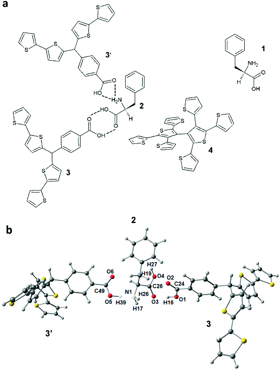 | ||
| Scheme 1 (a) Structural formulas of D-phenylalanine 1, the pre-polymerization complex of L-phenylalanine 2 with two molecules of the functional monomer, p-bis(2,2′-bithien-5-yl)methylbenzoic acid 3 and 3′, in the presence of the cross-linking monomer, 2,4,5,2′,4′,5′-hexa(thiophen-2-yl)-3,3′-bithiophene 4, and (b) the B3LYP/6-21G* optimized structure of the pre-polymerized L-phenylalanine 2 complex with the functional monomer molecules 3 and 3′. | ||
Fig. 1 shows the current–potential curves for the potentiodynamic electropolymerization of L-Phe (Fig. 1a) and D-Phe (Fig. 1b) resulting in the deposition of respective MIP films on the Pt disk electrodes. In the first cycle, the anodic peak at ∼1.0 V corresponds to the irreversible electro-oxidation of the bis(bithiophene) moiety. During this electro-oxidation, a radical cation is formed.47 This peak decreased in subsequent cycles indicating the formation of a less conducting MIP film.
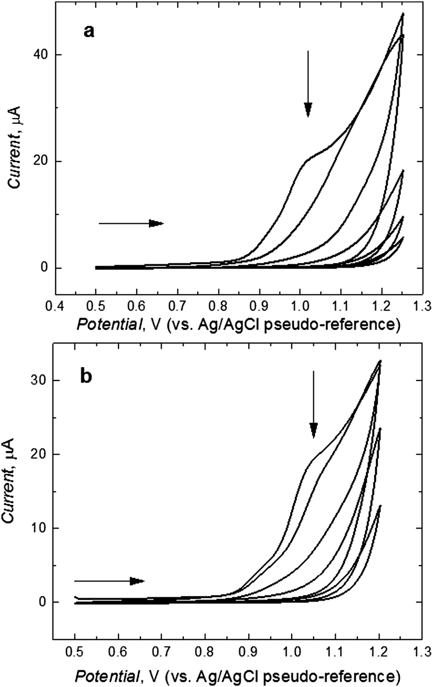 | ||
| Fig. 1 The current–potential curves for (a) MIP-(L-Phe) and (b) MIP-(D-Phe) film deposition by potentiodynamic electropolymerization on the 1 mm diameter Pt disk electrode in solution of 0.1 mM 1 or 2, 0.2 mM 3, 0.1 mM 4, and 0.1 M (TBA)ClO4 in the CH3CN-to-H2O solvent mixture of the 9:1 volume ratio. The potential scan rate was 50 mV s−1. | ||
After rinsing with acetonitrile, the D- or L-Phe template was extracted from the MIP film for the application of this film as the chemosensor recognition unit. To control the progress of Phe removal, the gate effect of the MIP film was examined (Fig. 2).48 For that, the electro-oxidation of a K4Fe(CN)6 redox probe was followed by DPV at the MIP film coated electrode for different time spans of template extraction. Apparently, removal of the template from the MIP molecular cavities resulted in the increase of the DPV peak current for the redox probe oxidation (Fig. 2). Finally, 90 min extraction with 10 mM NaOH appeared to be optimized (curve 5 in Fig. 2).
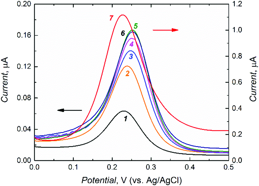 | ||
| Fig. 2 Differential pulse voltammetry (DPV) curves for 0.1 M K4Fe(CN)6 in 0.1 M KNO3 at the MIP-(D-phenylalanine) film coated 1 mm diameter Pt disk electrode, (1 – black) before D-phenylalanine extraction and after extraction with 10 mM NaOH for (2 – orange) 10, (3 – blue) 45, (4 – magenta) 60, (5 – green) 90, (6 – brown) 105 min, and (7 – red) for the bare Pt electrode. | ||
D-Phe template extraction from the MIP film was confirmed by the PM IRRAS spectroscopy measurements. Fig. S1 (ESI†) presents the experimental spectra recorded for the MIP film before and after D-Phe extraction and the NIP film along with calculated and scaled theoretical frequencies of normal modes. The band assigned to the perchlorate anion was removed before the band assignment to normal modes calculated for the MIP before and after extraction. Briefly, the (D-Phe)-templated MIP film showed (Fig. S1a, ESI†) peaks at ∼1666 cm−1 corresponding to the N–H bending of the primary amine functionality of D-Phe. Vibration of the carboxy group of D-Phe resulted in the peak at 1688 cm−1. In the calculated spectrum, these peaks appeared at 1645 cm−1 and 1678 cm−1, respectively (Fig. S1a, ESI†). Importantly, these peaks disappeared after D-Phe extraction from the MIP film (Fig. S1b, ESI†). The IR spectrum of the NIP film (Fig. S1c, ESI†) was similar to that of the MIP film after template extraction (Fig. S1b, ESI†).
The morphology of the polymer plays an important role if it is used as a recognition unit of a chemosensor. The polycrystalline morphology is preferable because a polycrystalline organic polymer film exhibits better sensing properties than an amorphous polymer film in terms of response, repeatability, and reproducibility.49 Therefore, the morphology of polymer films was herein examined with AFM imaging.
A distinct surface morphological pattern was observed in AFM images of different MIP and NIP samples (Fig. 3). Brighter areas in the images correspond to bigger polymer grains. Interestingly, the (D-Phe)-templated MIP film was enriched with grains of bigger size, ∼70 nm (Fig. 3a). However, smaller grains, ∼35 nm, appeared (Fig. 3b) after the extraction of the template with 10 mM NaOH. The morphology of the NIP film was similar to that of the (D-Phe)-templated MIP film (Fig. 3c), i.e. it was composed of bigger grains, ∼69 nm. Moreover, the thickness of the MIP film before the extraction of the D-Phe template equaling 224 ± 14 nm decreased to 175 ± 51 nm after extraction. Presumably, this decrease resulted from the removal of loose parts of the deposited MIP film. The thickness of the NIP film was 221 ± 24 nm.
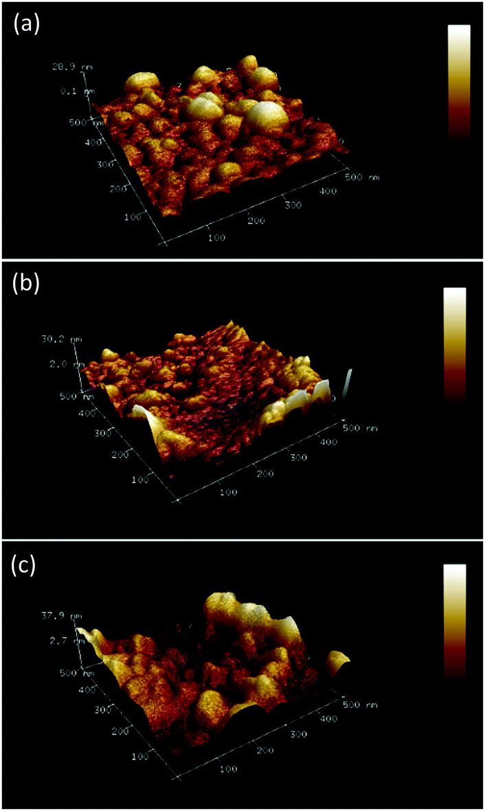 | ||
| Fig. 3 Atomic force microscopy images recorded using ScanAsyst Mode™ for the film of (a) (D-phenylalanine)-templated MIP, (b) (D-phenylalanine)-extracted MIP, and (c) non-imprinted polymer (NIP). Image dimensions (0.5 × 0.5) μm2. | ||
The morphologies of both MIP and NIP films were further investigated by SEM. The SEM images of the (D-Phe)-templated MIP film before and after template extraction along with those of the NIP film before and after similar treatment are shown in Fig. S2 (ESI†). The imaging showed that the MIP film was composed of small densely packed grains of the same size (Fig. S2a and b, ESI†). However, some irregular granules are also seen on top of smaller grains. NIP films reveal similar morphology (Fig. S2c and d, ESI†). Typically, the conductivity of such a compact film is high,51 a desired property for a FET based chemosensor.
After template extraction, D- or L-Phe analyte binding by respective MIPs was examined. For the determination of this binding, electrical transduction using an EG-FET was applied.
In comparison to the commonly available metal oxide based FET sensing systems, conducting polymer film based recognition units are preferred because they can operate at ambient temperature. Moreover, conducting polymers, due to their semiconducting and redox properties, undergo changes in their electrical conductivity upon changes in the number of charge carriers incurred by doping/dedoping, interactions of ions, or charge transfer between molecules. Besides, conducting polymers with higher conductivity may help to overcome problems with Debye length limitations inherent to FET transducers. All of these make the use of conducting polymers in FETs for sensing applications very promising.49
An EG-FET is a MOSFET modification, in which the gate is extended outside of the transistor. Therefore, the operation principle of the EG-FET remains within the scope of the basic MOSFET description. Scheme 2 shows the experimental setup with the MIP film deposited on the working electrode (WE), i.e. the extended gate, and the Pt plate reference electrode (RE). When a positive with respect to the source of the n-type channel MOSFET voltage is applied to the gate, electrons (majority carriers in the substrate) are attracted to the surface of the gate and form a conducting channel between the source and the drain. Fundamentals of the electric method used are described elsewhere.52,53 Accordingly, the transistor characteristics were determined at the constant gate voltage vs. the Pt reference electrode, VR = 1.50 V while the drain voltage (VD) was scanned from 0 to 5.0 V. The change in the resulting drain current (ID) was measured. This change, recorded for different concentrations of the analyte, was used to monitor the binding of the analyte molecule to its molecular cavity from 10 mM NaH2PO4.
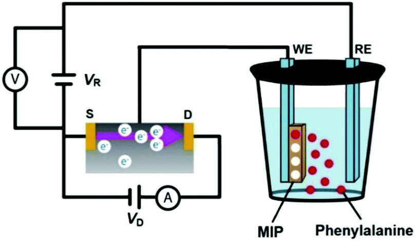 | ||
| Scheme 2 The experimental setup, based on the EG-FET design, using an Au-glass slide coated with the phenylalanine-templated MIP film or NIP film as the gate (working electrode, WE), and a Pt plate as the reference electrode (RE). Symbols D and S stand for the drain and source components of the EG-FET structure, respectively. The reference electrode was polarized to VR = 1.50 V (adapted from ref. 50). | ||
Fig. 4 shows the dependence of the change in the drain current on the D- or L-Phe concentration, as determined from the EG-FET characteristics. The recorded ID changes are attributed to the interfacial potential shift at the (extended gate)–solution interface. The correlation between the change in the drain current and the analyte concentration in solution was linear up to 100 μM Phe (both D- and L-Phe form). Importantly, these chiral MIP films were cross-selective. To determine enantioselectivity in both cases, we compared the slopes of calibration plots for D- and L-Phe at MIP-(D-Phe) and MIP-(L-Phe). The MIP-(D-Phe) was highly sensitive to D-Phe (curve 1 in Fig. 4a). However, advantageously, the response of this MIP to the addition of L-Phe was appreciably low (curve 2 in Fig. 4a), which led to the enantioselectivity factor of ∼2.3, determined as the ratio of these slopes. Similarly, the MIP-(L-Phe) was very sensitive to L-Phe and its sensitivity to D-Phe (curves 1′ and 2′, respectively, in Fig. 4b) was low, resulting in the enantioselectivity factor of ∼2.3. This difference in behavior most likely arises from the presence of chiral cavities generated during respective imprinting. Table 2 summarizes the analytical parameters determined for the devised chemosensors.
 | ||
| Fig. 4 Calibration plots for (a) the (D-phenylalanine)-templated MIP film for (1) D-phenylalanine, (2) L-phenylalanine, and (b) the (L-phenylalanine)-templated MIP film, for (1′) L-phenylalanine (2′) D-phenylalanine. MIP films were deposited on the Au-glass slide gates of the EG-FET transducer. Curves (3) and (3′) are calibration plots for D- and L-phenylalanine, respectively, for the NIP film. VR = 1.50 V. | ||
| MIP | Analytical parameter | Interference | Value ± st. dev. |
|---|---|---|---|
| D-Phenylalanine templated MIP | Sensitivity to D-phenylalanine, μA mM−1 | 0.43 ± 0.02 | |
| Linear dynamic concentration range, μM | 13–100 | ||
| Limit of detection at 3σ, μM | 13 | ||
| Sensitivity to interference, μA mM−1 | L-Phenylalanine | 0.19 ± 0.02 | |
| D-Alanine | 0.20 ± 0.02 | ||
| D-Tyrosine | 0.06 ± 0.01 | ||
| D-Proline | 0.20 ± 0.02 | ||
| L-Phenylalanine templated MIP | Sensitivity to L-phenylalanine, μA mM−1 | 0.90 ± 0.07 | |
| Linear dynamic concentration range, μM | 13–100 | ||
| Limit of detection at 3σ, μM | 13 | ||
| Sensitivity to interference, μA mM−1 | D-Phenylalanine | 0.39 ± 0.01 | |
| D-Alanine | 0.42 ± 0.03 | ||
| D-Tyrosine | 0.43 ± 0.01 | ||
| NIP | Sensitivity to D-phenylalanine, μA mM−1 | 0.012 ± 0.03 | |
In order to confirm the imprinting, an NIP film deposited on the Au-glass slide electrode was assembled in the EG-FET system as a control. Because of the absence of molecular cavities, binding of D-Phe to the NIP was low (curve 3 in Fig. 4a). Therefore, sensitivity of the NIP electrode towards D-Phe was much lower than that of the MIP electrode (Table 2). The chemosensor behaved similarly to L-Phe (curve 3′ in Fig. 4b). Evidently, the low sensitivity of the NIP film to Phe confirmed the importance of imprinting molecular cavities in the MIP. From the ratio of the sensitivity of the MIP-(D-Phe) and NIP chemosensor to D-Phe (curves 1 and 3 in Fig. 4a, respectively), the apparent imprinting factor (AIF) was determined to be very high equaling 36.
Then, the selectivity of both MIP films with respect to functionally and structurally similar interferences including D-tyrosine, D-proline, and D-alanine was evaluated (Fig. S3 and S4, ESI†). The results of selectivity studies are summarized in Table 2. The MIP-(D-Phe) chemosensor sensitivity to D-Phe was ∼7 times that to D-tyrosine as well as over twice that to D-alanine and D-proline. Similarly, the sensitivity of the MIP-(L-Phe) chemosensor to L-Phe was nearly twice that to D-tyrosine, D-alanine, and D-proline. Remarkably, the charge of Phe and most of its interferences was positive under the measurement conditions. Therefore, the change in the drain current corresponded to the extent of selective binding of the analyte to its MIP molecular cavities.
Moreover, the selectivity of the devised chemosensor in complex samples was studied (Fig. 5). For that, the concentration of D-Phe was determined in the presence of equimolar concentrations of L-Phe, D-alanine, L-tyrosine, and L-proline. The results showed only a slight increase of the drain current (∼10%) in the presence of these interferences (Fig. 5E), thus confirming the suitability of the fabricated chemosensor for real applications.
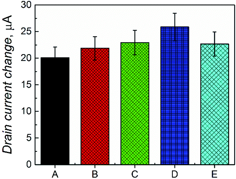 | ||
| Fig. 5 The change in drain currents for the MIP-(D-Phe) film coated gate in the presence of (A) D-Phe, (B) D-Phe and D-alanine, (C) D-Phe, D-alanine, and L-proline, (D) D-Phe, D-alanine, L-proline and L-tyrosine. (E) D-Phe, D-alanine, L-proline, L-tyrosine and L-Phe. Concentration of D-Phe and each interference was 50 μM. VR = 1.50 V. | ||
Determination of the imprinting factor
In the field of molecular imprinting, the imprinting factor is the measure of the concentration of selective molecular cavities in the MIP network. The analytical signal response of the MIP is compared with that of NIP to determine this factor. The strength of multiple interactions of the analyte molecules with matching molecular cavities determines this value. In the present study, a high value of AIF was determined from the ratio of slopes of calibration curves for the MIP and NIP EG-FET chemosensors. However, this approach does not provide the true imprinting factor value. This is because several factors other than the presence of the analyte in MIP, such as the charge or the dipole moment of the analyte, may govern the ID change measured. Therefore, PM transduction was used to determine true amounts of the analyte bound to the MIP and NIP films.For that, the MIP-(D-Phe) thin film was deposited on an Au-QCR mounted in the FIA holder.42 100 μL sample solutions of increasing D-Phe concentrations were injected under FIA conditions for constructing calibration plots. The change in the resonance frequency (Δf) is opposite to the change in the mass of the Au-QCR with the deposited MIP or NIP film, as the Sauerbrey equation predicts. Each consecutive injection of different concentrations of D-Phe resulted in different changes in resonance frequency, thus confirming D-Phe binding to molecular cavities. Importantly, a similar change in the NIP film coated Au-QCR was much lower.
The measured frequency decrease obeyed the linear regression equation of Δf (Hz) = −7.04 (Hz mM−1) c (mM) − 2.02 (Hz) for the analyte concentration up to 20 mM with a sensitivity of −7.04 ± 0.97 Hz mM−1 and the correlation coefficient of 0.93 (curve 1 in the inset to Fig. 6). Similarly, the resonance frequency changes corresponding to analyte binding by the NIP film were measured to construct the calibration plot (curve 2 in the inset to Fig. 6). The sensitivity of the NIP film to D-Phe (−0.57 ± 0.16 Hz mM−1) was determined from the slope of a similar FIA calibration plot described using the following equation. Δf (Hz) = −0.57 (Hz mM−1) c (mM) − 6.65 (Hz). The correlation coefficient was 0.74. From the ratio of sensitivity to D-Phe of the MIP-(D-Phe) and that of the NIP, the imprinting factor was determined to be relatively high equaling 12. This relatively high imprinting factor confirms the high concentration of molecular cavities in the MIP. Moreover, this result confirms the superiority of EG-FET transducers over piezoelectric microgravimetry transducers. That is, the detectability of the former (13 μM) was much higher than that of the latter (up to 5 mM).
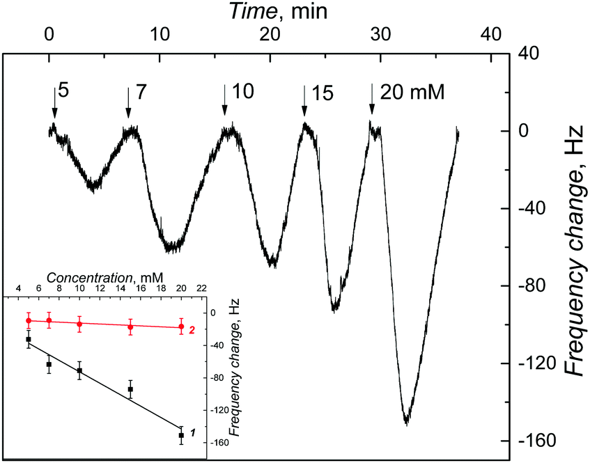 | ||
| Fig. 6 The resonance frequency change with time after injection of 100 μL samples of D-Phe of different concentrations, indicated with numbers at curves, under FIA conditions, for the (D-Phe)-templated MIP film. A 10 mM NaH2PO4 served as the carrier solution. The inset presents calibration plots for D-Phe on the Au-QCR coated with the (1) MIP and (2) NIP film. | ||
Conclusions
We fabricated two EG-FET based MIP chemosensors, each for the enantioselective determination of given phenylalanine enantiomers. For this determination, thin MIP films were deposited by electropolymerization on the surfaces of extended gates of field-effect transistors. The resulting chemosensors successfully determined D- and L-Phe in the concentration range of 13 to 100 μM with the limit of detection of 13 μM Phe and the ∼2.3 enantioselectivity factor. Moreover, they selectively discriminated between the D- and L-form of phenylalanine and they were selective with respect to the interferences from common amino acids including D-proline, D-alanine, and D-tyrosine.Acknowledgements
The present research was financially supported by the Polish National Science Centre, NCN (Grant No. 2013/11/N/ST5/01907 to Z. I.). W. K. and K. N. acknowledge NCN (Grant No. 2014/15/B/NZ7/01011 and 2014/15/B/ST4/04642, respectively) for financial support. P. S. S. acknowledges the Ministry of Science and Higher Education of Poland (Grant No. IP2014 041473) for financial support. F. D. acknowledges the National Science Foundation (Grant No. 1401188 as well as UNT-AMMPI) for financial support. We thank Dr Tiziana Benincori (Department of Chemical and Environmental Sciences, University of Insubria, Como, Italy) for synthesizing cross-linking monomer 4.References
- B. Waldeck, Chirality, 1993, 5, 350–355 CrossRef CAS PubMed.
- J. McConathy and M. J. Owens, J. Clin. Psychiatry, 2003, 5, 70–73 Search PubMed.
- Y. Nie, X. Liu, X. Yang and Z. Zhao, J. Chromatogr. Sci., 2013, 51, 753–763 CAS.
- G. Gubitz and M. G. Schmid, Biopharm. Drug Dispos., 2001, 22, 291–336 CrossRef CAS PubMed.
- P. M. Davadra, T. K. Patel, J. C. Chauhan, R. K. Kharul, B. Pandey, M. R. Jain and A. H. Bapoda, Chirality, 2011, 23, 277–280 CrossRef CAS PubMed.
- D. Guillarme, G. Bonvin, F. Badoud, J. Schappler, S. Rudaz and J.-L. Veuthey, Chirality, 2010, 22, 320–330 CAS.
- Z. A. Al-Othman, A. Al-Warthan, S. D. Alam and I. Ali, Biomed. Chromatogr., 2014, 28, 1514–1524 CrossRef CAS PubMed.
- J. Zukowski, M. Brightwell and V. D. Biasi, Chirality, 2003, 15, 600–604 CrossRef CAS PubMed.
- Y.-S. Lin, G.-M. Tu, C.-Y. Lin, Y.-T. Chang and Y.-P. Yen, New J. Chem., 2009, 33, 860–867 RSC.
- Y. Liu, T. Minami, R. Nishiyabu, Z. Wang and P. A. Jr, J. Am. Chem. Soc., 2013, 135, 7705–7712 CrossRef CAS PubMed.
- K. Ghosh and T. Sarkar, Tetrahedron Lett., 2014, 55, 1342–1346 CrossRef CAS.
- Y. Ishige, M. Shimoda and M. Kamahori, Biosens. Bioelectron., 2009, 24, 1096–1102 CrossRef CAS PubMed.
- T. Minami, T. Minamiki, Y. Hashima, D. Yokoyama, T. Sekine, K. Fukuda, D. Kumaki and S. Tokito, Chem. Commun., 2014, 50, 15613–15615 RSC.
- L. Torsi, M. Magliulo, K. Manoli and G. Palazzo, Chem. Soc. Rev., 2013, 42, 8612–8628 RSC.
- P. Lin and F. Yan, Adv. Mater., 2012, 24, 34–51 CrossRef CAS PubMed.
- S. Suriyanarayanan, P. J. Cywinski, A. J. Moro, G. J. Mohr and W. Kutner, Top. Curr. Chem., 2012, 325, 165–266 CrossRef CAS PubMed.
- Z. Iskierko, P. S. Sharma, K. Bartold, A. Pietrzyk-Le, K. Noworyta and W. Kutner, Biotechnol. Adv., 2016, 34, 30–46 CrossRef CAS PubMed.
- P. S. Sharma, F. D'Souza and W. Kutner, TrAC, Trends Anal. Chem., 2012, 34, 59–77 CrossRef CAS.
- P. S. Sharma, Z. Iskierko, A. Pietrzyk-Le, F. D'Souza and W. Kutner, Electrochem. Commun., 2015, 50, 81–87 CrossRef CAS.
- P. S. Sharma, A. Pietrzyk-Le, F. D'Souza and W. Kutner, Anal. Bioanal. Chem., 2012, 402, 3177–3204 CrossRef CAS PubMed.
- T. S. Bedwell and M. J. Whitcombe, Anal. Bioanal. Chem., 2016, 408, 1735–1751 CrossRef CAS PubMed.
- H. Khan and J. K. Park, Biotechnol. Bioprocess Eng., 2006, 11, 503–509 CrossRef CAS.
- L. Wu, Y. Gao and J. Wang, Anal. Lett., 2007, 40, 3129–3147 CrossRef CAS.
- A. Mirmohseni, M. Shojaei and M. Farbodi, Biotechnol. Bioprocess Eng., 2008, 13, 592–597 CrossRef CAS.
- C. N. Casey, S. E. Campbell, U. J. Gibson and T. School, Biosens. Bioelectron., 2010, 26, 703–709 CrossRef CAS PubMed.
- H. Qiu, Y. Xi, F. Lu, L. Fan and C. Luo, Spectrochim. Acta, Part A, 2012, 86, 456–460 CAS.
- X.-Y. Liu, H.-X. Fang and L.-P. Yu, Talanta, 2013, 116, 283–289 CrossRef CAS PubMed.
- C.-Y. Hsu, M.-H. Lee, J. L. Thomas, C.-P. Shih, T.-L. Hung, T.-J. Whang and H.-Y. Lin, Nanotechnology, 2015, 26, 305502 CrossRef PubMed.
- Y. Hoshino, T. Kodama, Y. Okahata and K. J. Shea, J. Am. Chem. Soc., 2008, 130, 15242–15243 CrossRef CAS PubMed.
- I. Chianella, A. Guerreiro, E. Moczko, J. S. Caygill, E. V. Piletska, I. M. P. D. V. Sansalvador, M. J. Whitcombe and S. A. Piletsky, Anal. Chem., 2013, 85, 8462–8468 CrossRef CAS PubMed.
- L. Ye and K. Mosbach, Chem. Mater., 2008, 20, 859–868 CrossRef CAS.
- P. Manesiotis, S. Kashani and P. McLoughlin, Anal. Methods, 2013, 5, 3122–3128 RSC.
- J. Yin, Z. Meng, M. Du, C. Liu, M. Song and H. Wang, J. Chromatogr. A, 2010, 1217, 5420–5426 CrossRef CAS PubMed.
- D. E. Matthews, J. Nutr., 2007, 137, 1549S–1575S CAS.
- N. E. Walsh, S. Ramamurthy, L. Schoenfeld and J. Hoffman, Arch. Phys. Med. Rehabil., 1986, 67, 436–439 CAS.
- C.-P. Chen, A. Ganguly, C.-Y. Lu, T.-Y. Chen, C.-C. Kuo, R.-S. Chen, W.-H. Tu, W. B. Fischer, K.-H. Chen and L.-C. Chen, Anal. Chem., 2011, 83, 1938–1943 CrossRef CAS PubMed.
- T.-P. Huynh, K. C. Chandra Bikram, W. Lisowski, F. D'Souza and W. Kutner, Bioelectrochemistry, 2013, 93, 37–45 CrossRef CAS PubMed.
- T.-P. Huynh, M. Sosnowska, J. W. Sobczak, C. B. KC, V. N. Nesterov, F. D'Souza and W. Kutner, Anal. Chem., 2013, 85, 8361–8368 CrossRef CAS PubMed.
- A. Pietrzyk, S. Suriyanarayanan, W. Kutner, E. Maligaspe, M. E. Zandler and F. D'Souza, Bioelectrochemistry, 2010, 80, 62–72 CrossRef CAS PubMed.
- F. Sannicolò, P. R. Mussini, T. Benincori, R. Martinazzo, S. Arnaboldi, G. Appoloni, M. Panigati, E. Q. Procopio, V. Marino, R. Cirilli, W. Kutner, K. Noworyta, A. Pietrzyk-Le, Z. Iskierko and K. Bartold, Chem. – Eur. J., 2016, 22, 10839–10847 CrossRef PubMed.
- W. Koh, W. Kutner, M. T. Jones and K. M. Kadish, Electroanalysis, 1993, 5, 209–214 CrossRef CAS.
- A. Kochman, A. Krupka, J. Grissbach, W. Kutner, B. Gniewinska and L. Nafalski, Electroanalysis, 2006, 18, 2168–2173 CrossRef CAS.
- M. J. Frisch, et al., Gaussian 09, Gaussian, Inc., Wallington CT, 2009 Search PubMed.
- M. H. Jamróz, Spectrochim. Acta, Part A, 2013, 114, 220 CrossRef PubMed.
- M. H. Jamróz, Vibrational energy distribution analysis, Spectroscopy and molecular modeling group, Institute of Nuclear Chemistry and Technology, Warsaw, Poland, 2004–2010 Search PubMed.
- M. H. Jamróz, SPESCA, Spectroscopy and molecular modeling group, Institute of Nuclear Chemistry and Technology, Warsaw, Poland, 2014 Search PubMed.
- J. Heinze, B. A. Frontana-Uribe and S. Ludwigs, Chem. Rev., 2010, 110, 4724–4771 CrossRef CAS PubMed.
- Y. Yoshimi, K. Sato, M. Ohshima and E. Piletska, Analyst, 2013, 138, 5121–5128 RSC.
- T.-P. Huynh, P. S. Sharma, M. Sosnowska, F. D'Souza and W. Kutner, Prog. Polym. Sci., 2015, 47, 1–25 CrossRef CAS.
- Z. Iskierko, P. S. Sharma, D. Prochowicz, K. Fronc, F. D'Souza, D. Toczydłowska, F. Stefaniak and K. Noworyta, ACS Appl. Mater. Interfaces, 2016, 8, 19860–19865 CAS.
- K. M. Choi, C. Y. Kim and K. H. Kim, J. Phys. Chem., 1992, 96, 3782–3788 CrossRef CAS.
- M. Dabrowski, P. S. Sharma, Z. Iskierko, K. Noworyta, M. Cieplak, W. Lisowski, S. Oborska, A. Kuhn and W. Kutner, Biosens. Bioelectron., 2016, 79, 627–635 CrossRef CAS PubMed.
- Z. Iskierko, M. Sosnowska, P. S. Sharma, T. Benincori, F. D'Souza, I. Kaminska, K. Fronc and K. Noworyta, Biosens. Bioelectron., 2015, 74, 526–533 CrossRef CAS PubMed.
Footnote |
| † Electronic supplementary information (ESI) available: Structural formulas of functional monomers used for modelling the pre-polymerization complex structure. The change of the Gibbs free energy (ΔG) corresponding to the formation of the complex of D-phenylalanine with different functional monomers, in vacuum, calculated using the DFT B3LYP/3-21G* method. FTIR spectra recorded for the (D-phenylalanine)-templated MIP film before and after D-phenylalanine template extraction along with calculated and scaled theoretical frequencies of normal modes. SEM images of the MIP and NIP film. Calibration plots for D-phenylalanine, D-proline, D-alanine, and D-tyrosine at the (D-phenylalanine)-templated MIP film deposited on the Au-glass slide gate (working electrode) of the EG-FET. Calibration plots for L-phenylalanine, D-tyrosine, and D-alanine at the (L-phenylalanine)-templated MIP film deposited on the Au-glass slide gate (working electrode) of the EG-FET. See DOI: 10.1039/c6tc03812c |
| This journal is © The Royal Society of Chemistry 2017 |