
 Open Access Article
 This Open Access Article is licensed under a Creative Commons Attribution-Non Commercial 3.0 Unported Licence
Towards centimeter thick transparent wood through interface manipulation†
Yuanyuan
Li
 a,
Xuan
Yang
a,
Qiliang
Fu
a,
Ramiro
Rojas
a,
Min
Yan
*b and
Lars
Berglund
*a
a,
Xuan
Yang
a,
Qiliang
Fu
a,
Ramiro
Rojas
a,
Min
Yan
*b and
Lars
Berglund
*a
aWallenberg Wood Science Center, Department of Fiber and Polymer Technology, KTH Royal Institute of Technology, SE-10044 Stockholm, Sweden. E-mail: blund@kth.se
bSchool of Engineering Science, Department of Applied Physics, KTH Royal Institute of Technology, SE-16440 Kista, Sweden. E-mail: miya@kth.se
First published on 13th December 2017
Abstract
Transparent wood is an attractive structural material for energy-saving buildings due to its high optical transmittance, good thermal insulation, and high toughness. However, thick highly transparent wood is challenging to realize. In the current work, highly transparent wood (1.5 mm) with a transmittance of 92%, close to that of pure PMMA (95%), is demonstrated. The high transmittance was realized by interface manipulation through acetylation of wood template. Both experiments and electromagnetic modeling support that the improved transmittance is mainly due to elimination of interface debonding gap. By applying this method, a centimeter-thick transparent wood structure was obtained. The transparent wood could be used as a substrate for an optically tunable window by laminating a polymer dispersed liquid crystal (PDLC) film on top. The techniques demonstrated are a step towards the replacement of glass in smart windows and smart buildings.
Introduction
Reducing energy consumption in the building sector has gained attention due to the rapid increase in energy expenditure, shortage of energy resources, and the related environmental burden.1 In this context, energy-saving buildings are desirable where light transmitting and thermal insulating properties are important.2 Glass has been widely used for light transmitting buildings. However it suffers from brittleness and shattering type of failure, which can potentially cause safety issues. Light transmitting concrete with optical fiber inclusions is another option.3 The main problem at the moment is the relatively high cost and difficulties in casting.Wood has been used in buildings for centuries and now is attractive in energy harvesting system.4,5 Recently, successful fabrication of transparent wood has been reported based on either removal of light absorbing materials (mainly lignin) or lignin retaining modification by only removing chromophoric structure followed by introducing refractive index-matching polymer into wood template.6–9 Transparent wood is attractive in energy-saving buildings due to the combined good optical transmittance (transmittance over 85%), thermal insulation (thermal conductivity less than 0.32 W m−1 K−1), and favorable mechanical performance with shatterproof features.6,10 In addition, there is potential for transparent wood multi-functionalization such as luminescent transparent wood,11,12 magnetic transparent wood,13 heat-shielding transparent wood,14 and even wood-based active photonic devices.15 However, centimeter thick transparent wood is challenging to realize. We reported 1 mm thick balsa based transparent wood with a transmittance of about 85% with thickness in the radial direction.6 Zhu et al.7 obtained 2 mm thick basswood based transparent wood with a transmittance of 80% with thickness perpendicular to longitudinal direction. With thickness in the longitudinal direction, a 3 mm-thick transparent wood with transmittance of 90% was demonstrated. When wood thickness is in the longitudinal direction, light mainly propagates in the neat polymer, and relatively thick transparent wood can be obtained. Two limitations for transparent wood with thickness in the longitudinal direction are that the in-plane mechanical performance is much inferior and the size of the structure is limited by the wood/tree cross-section. This restricts the application of transparent wood where thick, strong, and large building blocks are needed. Thus, thick transparent wood with thickness perpendicular to longitudinal direction is more attractive, albeit more challenging. In this work, we focus on wood veneer with thickness perpendicular to longitudinal direction.
In previous work, transparent wood demonstrated much lower transmittance (less than 85%) than neat polymer (around 95%), and the transmittance decreased sharply with respect to wood thickness.6 We propose that the main reason of the decreased transparency is due to the interface debonding cracks between PMMA and the wood cell wall, in addition to mismatch in refractive index between wood and infiltrated PMMA (refractive index is 1.49 for PMMA and 1.53 for holocellulose). Although polymers are fully infiltrated into the wood cell lumens, the interface debondings may still be present.11 The presence of interface debondings introduced more optical heterogeneity due to the low refractive index of air (i.e. 1) in the debonding gap, leading to stronger light scattering and thereby decreased transmittance. The interface gap is mainly caused by poor compatibility between wood cell wall, which is more hydrophilic in nature, and infiltrated polymers (such as PMMA, epoxy resin, styrene, vinyl carbazole, iso-bornyl methacrylate etc.), which are hydrophobic in nature.16,17 Moreover, polymer volume shrinkage occurs during polymerization, further promoting the formation of interface gaps.18 If better surface compatibility between PMMA and wood cell wall can be achieved, one can potentially eliminate or reduce interface debonding. In this way, higher transmittance could be obtained, which will pave the way for thick transparent wood fabrication. Surface manipulation is a common and useful strategy to solve the compatibility issues, including the use of compatibilizer19 and surface modification.20 Acetylation is an efficient method to hydrophobilize wood or lignocellulose pulp, which has been studied to reduce wood moisture sensitivity and increase compatibility with plastics such as polyethylene and polypropylene.21,22 As a result, for cellulose-based composites, acetylation also improves optical transmittance.23–25
In the current work, we apply surface acetylation on delignified wood substrates before PMMA infiltration to improve compatibility between wood template and PMMA, leading to reduced interface debonding and improved optical transmittance. Fig. 1a demonstrates the structure of the highly transparent wood. The acetylation of the delignified wood template introduced acetate groups onto the wood fiber surface, making the fiber more compatible with PMMA. High optical transmittance of 92% was obtained with 1.5 mm thick transparent wood, almost the same as that of neat polymer (95%). The photograph in Fig. 1b demonstrates the improved transmittance of modified transparent wood (right) compared to non-modified transparent wood (left). The wood texture is almost invisible after interface improvement. By applying the same method, a centimeter thick transparent wood structure was obtained, which is a step towards light transmitting wooden structures for buildings.
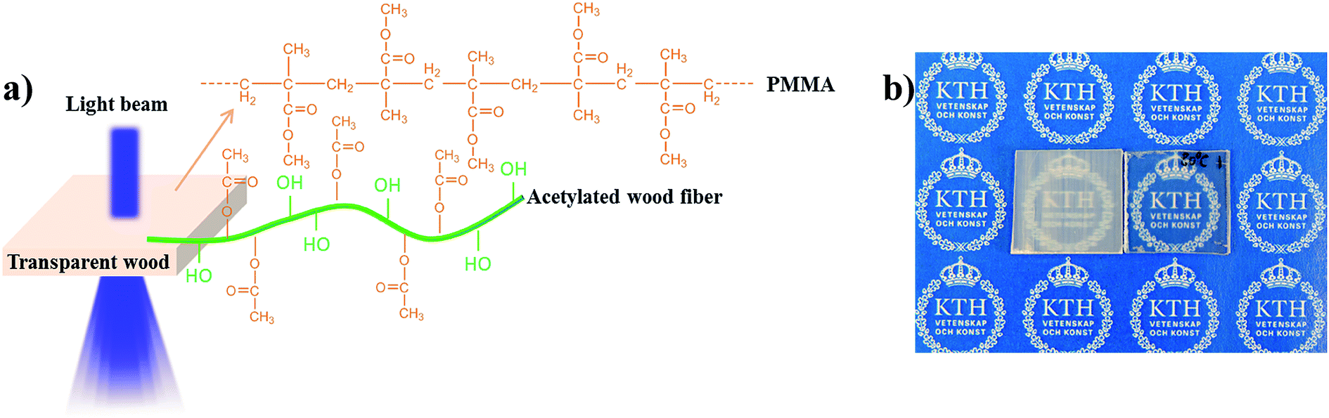 | ||
| Fig. 1 (a) Schematic representation showing the structure of the modified highly transparent wood. The wood template was acetylated to have better compatibility with PMMA. (b) Photograph shows the non-acetylated transparent wood (left) and acetylated transparent wood (right). | ||
Wood, especially delignified wood, is hydrophilic. This is principally due to the presence and exposure of hydroxyl groups.26 This leads to compatibility issues with hydrophobic polymers such as PMMA or epoxy, for transparent wood. Acetylation was carried out to solve the compatibility issue using acetic anhydride with pyridine as the catalyst. Prior to acetylation, wood was subjected to sodium chlorite treatment to remove the light absorbing components (mainly lignin) for transparent wood fabrication. A systematic study was conducted to obtain the optimized parameters for the acetylation based on wood templates with dimension of 25 × 25 × 1.5 mm. Fig. 2a shows the reaction of wood and acetic anhydride. Following the grafting of acetate groups onto wood fiber surface, the weight of the wood increased. Thus, the weight percentage gain (WPG) was used to estimate the degree of acetylation.27,28 When the reaction takes place at low temperature, the reaction time is long and the grafting efficiency is low. High temperature is better for high acetylation efficiency; however side reactions will increase, which will reduce the degree of substation instead.28 80 °C is found to be the optimal temperature with a WPG of about 7.3%. Time dependent acetylation degree was investigated by increasing the reaction time from 2 h to 12 h. The WPG increased quickly within the first 4 h and gradually stabilized after 6 h. As a compromise between reaction efficiency and time, smaller wood pieces were reacted for 6 h, while large and thick samples were subjected to 10 h reaction to allow homogeneous reaction through the whole wood template. After acetylation, the wood template turned yellowish, which led to yellowish transparent wood. Therefore, an additional sodium chlorite treatment was performed after acetylation to remove the yellowish color. Fourier transform infrared spectroscopy (FTIR)29 confirmed the successful grafting of acetate groups onto the wood template. The presence of a peak around wavenumber of 1370 cm−1 refers to the C–H vibration of methoxy groups, indicative of acetate groups on the modified wood. The peaks at the wavenumbers around 1227 and 1738 cm−1 refer to C–O and C![[double bond, length as m-dash]](https://www.rsc.org/images/entities/char_e001.gif) O stretching modes respectively. The increased intensity of these two peaks further confirms the introduction of acetate groups. The broad peak around wavenumber of 3300 cm−1 refers to –OH absorption. The decreased intensity corresponds to reduction of hydroxyl groups, mainly due to the grafting of acetate groups (Fig. 2a).
O stretching modes respectively. The increased intensity of these two peaks further confirms the introduction of acetate groups. The broad peak around wavenumber of 3300 cm−1 refers to –OH absorption. The decreased intensity corresponds to reduction of hydroxyl groups, mainly due to the grafting of acetate groups (Fig. 2a).
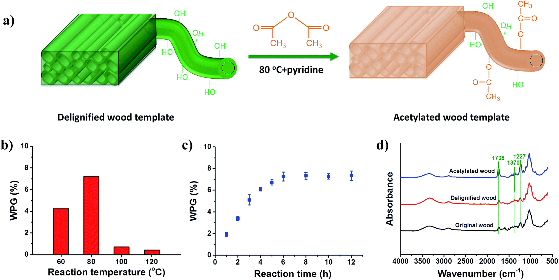 | ||
| Fig. 2 (a) Acetylation reaction of wood. (b) Temperature dependent WPG of the wood acetylation reaction. (c) Reaction time dependent WPG of the wood acetylation reaction. (d) FTIR spectra of original wood, delignified wood template, and acetylated wood template. | ||
After infiltration of PMMA into the wood template, highly transparent wood (1.5 mm thick) was obtained, as shown in Fig. 1b. The total transmittance reached 92 ± 1% in the visible wavelength range (Fig. 3a), much higher than the non-acetylated transparent wood (83 ± 2%), and even similar to neat PMMA (95%). The wood texture is not obviously visible, demonstrating the improved compatibility between PMMA and wood template. The improvement for transmittance is more obvious as the wood thickness increases. When wood thickness is 3 mm, the transmittance for acetylated transparent wood at a wavelength of 550 nm is 89%. In contrast, the transmittance for non-acetylated transparent wood is only 60%. Moreover, the increased compatibility between components leads to more optically homogeneous materials, resulting in lower light attenuation (high optical transmittance) and light scattering (lower optical haze). From Fig. 3b, the optical haze decreased drastically from 70% to 50% at wavelength of 550 nm for 1.5 mm thick samples. The decrease of haze was even larger for 3 mm thick samples, from 78% to 53%. Still, the haze remained much higher than that of pure PMMA or holocellulose nanopaper.30 One possible reason is the mismatch in refractive index between PMMA and wood cell wall. We also noticed that the transparent wood based on higher density wood shows more improvement in transmittance. For 1.5 mm thick birch transparent wood, with a cellulose volume fraction of around 30%, the transmittance increases from 64% to 90%. As a comparison, 1.5 mm balsa transparent wood with a low cellulose volume fraction of around 5%, shows a smaller increase in transmittance from 83% to 92%. This is also in line with our statement that PMMA–wood template interface debonding is the main factor making the optical transmittance of transparent wood inferior to neat PMMA. More data on acetylated transparent wood from different wood species are summarized in Table 1.
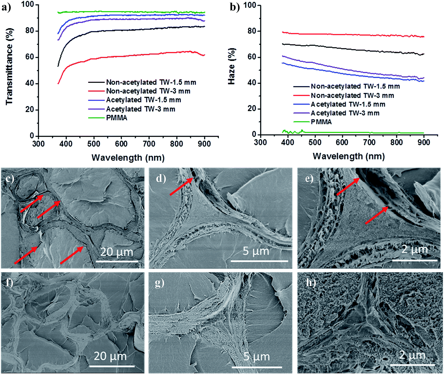 | ||
| Fig. 3 (a) Optical transmittance curves of acetylated and non-acetylated transparent wood samples. (b) Optical haze curves of acetylated and non-acetylated transparent wood. (c–e) Are the low- and high-magnification images of the non-acetylated transparent wood, exhibiting the aggregation of nanocellulose fibrils and the interface debonding gaps, (f–h) are the low magnification and high magnification images of the acetylated transparent wood. | ||
| Wood species | Polymer | Wood direction | Thickness (mm) | Transmittance (%) | Haze (%) | |
|---|---|---|---|---|---|---|
| a The transparent wood direction is marked as L when light propagates along the longitudinal direction. The transparent wood direction is marked as T when light propagates in the transverse plane (or perpendicular to wood longitudinal direction). | ||||||
| Current work acetylated transparent wood | Balsa | PMMA | T | 1.5 | 92 | 50 |
| 3 | 89 | 53 | ||||
| 7 | 71 | 74 | ||||
| 10 | 60 | 76 | ||||
| Birch | PMMA | T | 0.7 | 94 | 31 | |
| 1.5 | 90 | 52 | ||||
| Current work non-acetylated transparent wood | Balsa | PMMA | T | 0.7 | 89 | 50 |
| 1.5 | 83 | 70 | ||||
| 3 | 60 | 78 | ||||
| Birch | PMMA | T | 0.7 | 80 | 70 | |
| 1.5 | 64 | 79 | ||||
| Li et al.6 | Balsa | PMMA | T | 0.7 | 90 | ∼50 |
| 1.2 | 85 | 71 | ||||
| 3.7 | 40 | ∼80 | ||||
| Gan et al.13 | Cathay poplar | PMMA | — | 0.5 | 86.1 | — |
| Gan et al.12 | Cathay poplar | PMMA | T | 0.5 | 90.4 | — |
| Yu et al.14 | Beech | PMMA | L | 5 | 86 | 90 |
| Yaddanapudi et al.31 | Beech | PMMA | — | 0.1 | 70 | — |
| 0.3 | 30 | 18 | ||||
| 0.7 | 15 | 49 | ||||
| Zhu et al.7 | Bass | Epoxy | T | 2 | ∼80 | ∼85 |
| L | 2 | 90 | ∼95 | |||
| Zhu et al.32 | Bass | PVP | L | 0.1 to 1 | 90 ± 5 | 80 ± 5 |
| Li et al.10 | Bass | Epoxy | L | 5 | 90 | 95 |
To confirm improved compatibility between PMMA and modified wood template, SEM was applied to observe the non-acetylated and acetylated transparent wood cross-sections, where the PMMA–wood interface is visible. Fig. 3c–e are the low- and high-magnification SEM images of the non-acetylated transparent wood cross-sections, showing the successful infiltration of PMMA into the lumen. By examining the interface between PMMA and non-acetylated wood templates, the interface debondings are noticeable although in most regions the two materials show good bonding. The width of these interface debonding gaps can be in the order of hundreds of nanometers, which is similar to the wavelengths of visible light. In addition, nanocellulose fibers in most of the wood cell wall are aggregated, mainly due to the preferred interaction between cellulose (Fig. 3e). Interface debondings and cellulose aggregations would lead to more optical heterogeneity, resulting in lower optical transmittance and higher haze. In contrast to non-acetylated transparent wood, acetylated transparent wood showed nearly no interface debonding gap (Fig. 3f–g), and less aggregation in the cell wall (Fig. 3h), confirming improved compatibility between PMMA and the wood template.
To shed light on how the interface debonding gaps influence the optical properties of transparent wood, a full-wave numerical simulation based on the finite-element method (FEM) was carried out. A hypothesis was made that the interface debonding gap was uniformly distributed at all the interfaces between PMMA and inner wood cell wall and PMMA was only infiltrated into wood cell lumen. In our model, wood fibers were assumed to be hollow cylinders arranged in a triangular lattice, as depicted in Fig. 4a. The corresponding simulation results for transmittance are summarized in Fig. 4b and c. In general, the behavior of transmittance values for both transverse-electric (TE, or electrical field normal to incidence plane) and transverse-magnetic (TM, or magnetic field normal to incidence plane) polarizations are roughly the same, with TE polarization slightly more sensitive to the interface debonding gaps size. It was evident from the transmittance plots that, without interface debonding gaps, TE and TM transmittance values were around 95% across the whole visible wavelength range. Transmittance did not reach 100%, mainly due to the mismatch in refractive index between PMMA and wood cell wall. Strikingly, when a uniform 25 nm interface debonding gap was introduced, drastic decrease in transmittance (about 30% decrease) was observed, confirming the key role of interface debonding gap in the reduced transmittance. The presence of debonding gap creates interfaces with relatively high-index contrast, which increases scattering of light. As a result, a larger percent of light is heading backward after multiple scatterings, leading to lower transmittance. The modeled transmittance (around 70% with a wood thickness of 70 μm) was lower than our experimental data (80 ± 2% with the thickness of 1.5 mm). This is because in our model, the interface debonding gap is uniformly distributed at all the PMMA and inner wood cell wall interfaces. This is in contrast to the real samples, where the interface debonding gap is only present at some interfaces, not all of them. When the size of interface debonding gap increases to 100 and even 300 nm, the transmittance is further reduced, to even below 40% for the TE-polarization case.
 | ||
| Fig. 4 Numerical simulation data for transparent wood samples. (a) Schematic diagram of idealized wood structure used in the simulation. (b) TE transmittance for three samples with different gap sizes. (c) TM transmittance for three gap sizes. (d) Angular distribution of light after light transmission through a sample with no gap. (e) Angular distribution of light after light transmission through a sample with a gap size of 25 nm. Both (d) and (e) are with TE polarization. Results for TM polarizations are similar. | ||
The angular distribution of transmitted light was also calculated based on the above simulation method. This is related to haze data for the wood samples. Haze is the fraction of diffused transmitted light related to the total transmitted light. When no interface debonding gap exist, transmitted light propagates within an angular cone of less than ±20°. This is the consequence of light scattering due to the mismatch in refractive index between PMMA and wood cell wall. The modeling is in line with our experimental data, where acetylated transparent wood still showed haze as high as 50% although transmittance is similar to the neat polymer. As an interface debonding gap of 25 nm was introduced, strong light scattering occurs, with transmitted light propagating in an angular range of ±80°. The results are in support of the contribution of interface debonding gap to the haze of transparent wood samples. Reducing interface debonding gap will not only increase transmittance but also decrease haze of wood samples. This agrees with experimental data that, when surface-debonding gap was suppressed due to acetylation, the transmittance was increased from 82% to 93%, and the haze was decreased from 71% to 50%.
Centimeter-thick transparent wood is desirable for building applications. Our interface modification facilitates the fabrication of highly transparent thick wood. Applying the process described, a centimeter-thick transparent wood can be prepared. Fig. 5a shows a 7 mm thick transparent wood sample placed on top of printed letters “NOTEBOOK”, demonstrating a high transparency. The transmittance curves of the acetylated transparent wood with thickness of 1.5 mm, 3 mm, 7 mm, and 10 mm are presented in Fig. 5b. Fig. S1† shows the photograph of transparent wood with different thicknesses. The transmittance for 10 mm thick acetylated transparent wood is 40%, similar to the 3 mm thick balsa-based transparent wood without acetylation.6 Yet, the transmittance value is lower than 1.5 mm thick acetylated transparent wood (92%). This can be predicted from the Beer–Lambert Law.33 With higher thickness, the light propagation distance inside the transparent wood is increased, leading to less transmitted light. With increased thickness, also the haze was increased. Fig. 5c shows the optical haze curves of transparent wood. Haze has increased from less than 50% to more than 70% as the wood thickness increased from 1 mm to 10 mm, simply because a thicker sample induces increased light scattering at the wood/PMMA interfaces.
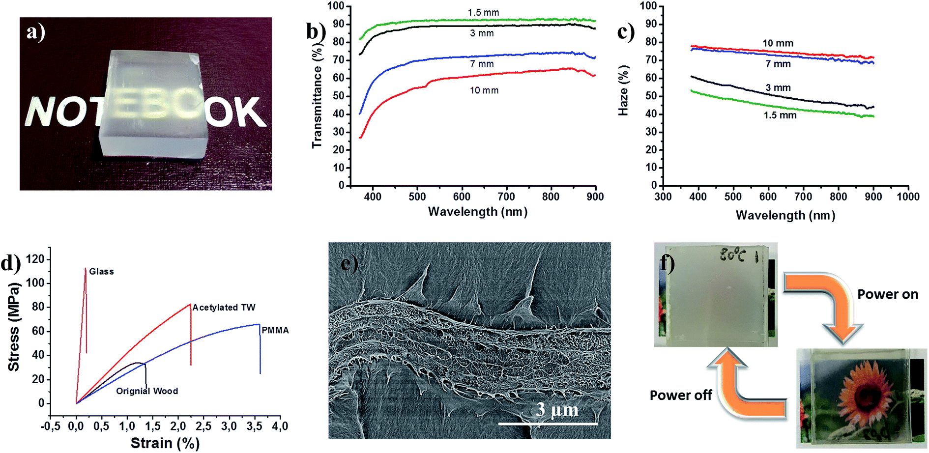 | ||
| Fig. 5 (a) A photo of 7 mm thick transparent wood with letters “NOTEBOOK” below, illustrating the transparency. (b) Optical transmittance curves of transparent wood with thickness of 1.5 mm, 3 mm, 7 mm, and 10 mm. (c) Optical haze curves of transparent wood with thicknesses of 1.5 mm, 3 mm, 7 mm, and 10 mm. (d) 3-point bending results of glass, acetylated transparent wood, PMMA, and original wood. (e) Cross-sectional SEM image of acetylated transparent wood after fracture, illustrating preserved bond between wood template and PMMA. (f) Smart wood window by lamination of PDLC film on transparent wood substrate. The transmittance is tunable by switching on/off electrical power. | ||
Mechanical performance of the acetylated transparent wood was characterized through 3-point bending test (Fig. 5d). Reinforcement effects were demonstrated from the improved moduli (4.0 GPa) and stress at break (78.9 MPa) compared with original wood (modulus of 3.4 GPa and stress at break of 32.8 MPa) and PMMA (modulus of 2.6 GPa and stress at break of 65.9 MPa). Wood properties are improved by filling pore space and improving stress transfer, PMMA properties are improved by reinforcement effect from cellulose fibers in the wood structure. This can be attributed to the strengthening effect from the wood template and the good interaction between nanocellulose in the wood template and PMMA. Fig. 5e shows the cross-sectional image of acetylated transparent wood after fracture, indicating strong interactions between wood and PMMA. To evaluate the potential of acetylated transparent wood for replacement of glass in building applications, the mechanical test of glass was also performed. Acetylated transparent wood exhibited much higher work of fracture (1.0 MJ m−3) than glass (0.1 MJ m−3). The composite structure ensures increased toughness and shattering type of failure is avoided for the acetylated transparent wood. This may be favorable with respect to safety problems of glass in building applications. In addition, transparent wood showed much lower density (around 1.2 g cm−3) than glass (between 2.4 g cm−3 and 2.8 g cm−3), which is favorable in the concept of lightweight building with improved earthquake resistance.
Smart windows with thermochromic34,35 or electrochromic36 functions by introducing functional polymers are attractive in the energy-saving building concept. The functional polymers can potentially be loaded into or applied on top of transparent wood. Here, transparent wood was applied as a substrate for a haze tunable smart window demonstration. An optically tunable polymer dispersed liquid crystal (PDLC) film was used as the functional layer laminated on top of transparent wood. Fig. S2† describes the mechanism and structure. Without power supply, the wood window showed good privacy protection due to the high haze generated from both transparent wood and the randomly arranged liquid crystals in the PDLC film. When power was applied, the window was transparent. This is due to low light scattering from the aligned liquid crystals modulated by the electric field. The demonstration shows that acetylated transparent wood could potentially be used for smart windows and buildings.
Conclusion
In conclusion, highly-transparent wood of 1.5 mm thickness with optical transmittance of 93% (similar to neat polymer) was obtained by interface manipulation of wood template. The improved transmittance is mainly due to the better compatibility between the PMMA and wood template after surface acetylation. Electromagnetic modeling results are in support of surface interface debonding gaps as the main factor controlling transmittance and haze. Mechanical performance shows synergy and reinforcement effect between wood templates and PMMA. A centimeter thick transparent wood structure with an optical transmittance of 60% was obtained. This concept paves the way for preparation of thick transparent wood for structural applications, such as smart windows and smart buildings.Materials and methods
Sodium chlorite delignification
Delignification process was performed using 1 wt% of sodium chlorite (NaClO2, Sigma-Aldrich) in acetate buffer solution (pH 4.6) at 80 °C according to the literature.6,37 The reaction was stopped until the wood became totally white. After delignification, the samples were carefully washed with deionized water and kept in water until further use. The wood samples are balsa (with thickness of 1.5, 3, 7, 10 mm) purchased from Wentzels Co. Ltd Sweden, and birch (with thickness of 0.7 and 1.5 mm) purchased from Glimakra of Sweden AB.Wood template acetylation
Before acetylation, delignified samples were dehydrated with ethanol and acetone sequentially. Each solvent exchange step was repeated 3 times. Wood acetylation was conducted using acetate anhydride (Sigma-Aldrich) with pyridine (Sigma-Aldrich) as the catalyst and N-methyl-2-pyrrolidone (NMP, Sigma-Aldrich) as the solvent. The volume ratio of acetic anhydride![[thin space (1/6-em)]](https://www.rsc.org/images/entities/char_2009.gif) :pyridine:NMP is 7:6:100. The weight to volume fraction of wood to acetate anhydride is 2 g/7 mL. The reaction was optimized with respect of temperature (60 °C, 80 °C, 100 °C, 120 °C), and time (1 h, 2 h, 3 h, 4 h, 5 h, 6 h, 8 h, 10 h, 12 h). The acetylated wood was further treated with NaClO until white due to discoloration after acetylation.
:pyridine:NMP is 7:6:100. The weight to volume fraction of wood to acetate anhydride is 2 g/7 mL. The reaction was optimized with respect of temperature (60 °C, 80 °C, 100 °C, 120 °C), and time (1 h, 2 h, 3 h, 4 h, 5 h, 6 h, 8 h, 10 h, 12 h). The acetylated wood was further treated with NaClO until white due to discoloration after acetylation.
Transparent wood preparation
Transparent wood fabrication was done according to our previous work.6 Before polymer infiltration, wood samples were dehydrated with ethanol and acetone sequentially. MMA monomer was pre-polymerized at 75 °C for 15 min with 0.3 wt% 2,2′-azobis(2-methylpropionitrile) (AIBN) as initiator followed by infiltration. Finally, the pre-polymerized MMA infiltrated wood template was sandwiched between two glass slides, packaged in aluminium foil, and cured in an oven at 70 °C for 4 h. For thick transparent wood, the pre-polymerized MMA infiltrated wood template was sealed in a beaker and cured at 50 °C for 24 h.Characterization
The cross-sections of wood samples were observed with a Field-Emission Scanning Electron Microscope (Hitachi S-4800, Japan) operating at an acceleration voltage of 1 kV. Freeze-drying was conducted on deionized water washed wood samples. The cross-section of the samples was prepared by fracturing the freeze-dried samples after immersed in liquid nitrogen. 3-point bending test of the transparent wood and glass was performed using an Instron 5944 with a 500 N load cell. The tests were carried out with 10% min−1 strain rate and 30 mm of span. All samples were cut into a strip (5 mm × 60 mm) for testing. The thickness of the samples is around 1.5 mm. The transmittance and haze were measured according to our previous work.6 A light source with wavelengths from 170 to 2100 nm was applied (EQ-99 from Energetiq Technology, Inc.). For transmittance measurements, the sample was put just in front of the sphere's incident beam input port, the spectrum was then directed out of another port of the sphere through an optical fiber and recorded. Haze measurement was recorded following the “Standard Method for Haze and Luminous Transmittance of Transparent Plastics” (STM D1003).38 For FTIR measurement, all the samples were 1.5 mm thick and freeze dried. An attenuated total reflectance (ATR) unit was used for the measurement. Polymer dispersed liquid crystal (PDLC) film was a self-adhesive film bought from Guangzhou Rushui industrial Co. Ltd. The transmittance and haze were 80% and 3.5% respectively when electricity was on. When electricity was off, the transmittance was 7%.Electromagnetic modeling methodology
A full-wave numerical calculation based on the finite-element method (FEM) was carried out to better understand the influences of interface debonding gap on the transparent wood optical properties (i.e. transmittance and angular distribution of transmitted light). The commercial software COMSOL Multiphysics was employed for such simulations. In our modeling, wood fibers are assumed to be hollow cylinders arranged in a triangular lattice. The lattice constant (period) is 20 μm. Four vertical layers of fibers are used for simulation; hence the simulated wood sample has an overall thickness of approximately 70 μm. Periodic boundary conditions are used on the left and right boundaries to emulate an infinitely extending structure. Perfectly matched layers are imposed on top of and also below the wood sample to absorb all out-going waves. The inner diameters of the cylinders are the same in each layer, but different in different layers. The inner diameter values are randomly generated between 18 to 20 μm, resulting in cell wall thicknesses ranging from 0.5 to 1.5 μm. The interstitial regions between the cylindrical fibers are assumed to have the same content as the fiber cell wall. The refractive indices of 1.53 and 1.49 were used for wood cell wall and PMMA respectively. A hypothesis was made that the interface debonding gap was uniformly distributed at all the interfaces between PMMA and inner wood cell wall and PMMA was only infiltrated into wood cell lumen. Depending on each sample, the gap size between PMMA-filled fiber core and cellulose inner wall is varied between 0 nm (no gap or debonding gap) to 300 nm. The same gap size is used for each sample. Plane-wave light incidence with a normal incidence angle is used for excitation. Two polarization scenarios, transverse-electric (TE, or electrical field normal to incidence plane) and transverse-magnetic (TM, or magnetic field normal to incidence plane) are calculated independently.Conflicts of interest
There are no conflicts to declare.Acknowledgements
We acknowledge funding from KTH and European Research Council Advanced Grant (No. 742733), Wood NanoTech. MY is supported by the Swedish Research Council (grant 2016-03911) and the Linnaeus center in Advanced Optics and Photonics (ADOPT). The electromagnetic computations were performed on resources provided by the Swedish National Infrastructure for Computing (SNIC) at the Center for High Performance Computing, KTH.References
- H. X. Zhao and F. Magoulès, Renewable Sustainable Energy Rev., 2012, 16, 3586–3592 CrossRef.
- B. Han, Y. Wang, S. Dong, L. Zhang, S. Ding, X. Yu and J. Ou, J. Intell. Mater. Syst. Struct., 2015, 26, 1303–1345 CrossRef.
- A. Losonczi, Translucent building block and a method for manufacturing the same, US pat. US8091303 B2, 2012.
- M. Adam, P. Strubel, L. Borchardt, H. Althues, S. Dörfler and S. Kaskel, J. Mater. Chem. A, 2015, 3, 24103–24111 CAS.
- F. Shen, W. Luo, J. Dai, Y. Yao, M. Zhu, E. Hitz, Y. Tang, Y. Chen, V. L. Sprenkle and X. Li, Adv. Energy Mater., 2016, 6, 1600377 CrossRef.
- Y. Li, Q. Fu, S. Yu, M. Yan and L. Berglund, Biomacromolecules, 2016, 17, 1358–1364 CrossRef CAS PubMed.
- M. Zhu, J. Song, T. Li, A. Gong, Y. Wang, J. Dai, Y. Yao, W. Luo, D. Henderson and L. Hu, Adv. Mater., 2016, 28, 5181–5187 CrossRef CAS PubMed.
- S. Fink, Holzforschung, 1992, 46, 403–408 CrossRef CAS.
- Y. Li, Q. Fu, R. Rojas, M. Yan, M. Lawoko and L. Berglund, ChemSusChem, 2017, 10, 3445–3451 CrossRef CAS PubMed.
- T. Li, M. Zhu, Z. Yang, J. Song, J. Dai, Y. Yao, W. Luo, G. Pastel, B. Yang and L. Hu, Adv. Energy Mater., 2016, 6, 1601122 CrossRef.
- Y. Li, S. Yu, J. G. C. Veinot, J. Linnros, L. Berglund and I. Sychugov, Adv. Opt. Mater., 2016, 5, 1600834 CrossRef.
- W. Gan, S. Xiao, L. Gao, R. Gao, J. Li and X. Zhan, ACS Sustainable Chem. Eng., 2017, 5, 3855–3862 CrossRef CAS.
- W. Gan, L. Gao, S. Xiao, W. Zhang, X. Zhan and J. Li, J. Mater. Sci., 2017, 52, 3321–3329 CrossRef CAS.
- Z. Yu, Y. Yao, J. Yao, L. Zhang, C. Zhang, Y. Gao and H. Luo, J. Mater. Chem. A, 2017, 5, 6019–6024 CAS.
- E. Vasileva, Y. Li, I. Sychugov, M. Mensi, L. Berglund and S. Popov, Adv. Opt. Mater., 2017, 5, 1700057 CrossRef.
- W. Gindl-Altmutter, M. Obersriebnig, S. Veigel and F. Liebner, ChemSusChem, 2015, 8, 87–91 CrossRef CAS PubMed.
- X. Qin, W. Xia, R. Sinko and S. Keten, Nano Lett., 2015, 15, 6738–6744 CrossRef CAS PubMed.
- F. Awaja, S. Zhang, M. Tripathi, A. Nikiforov and N. Pugno, Prog. Mater. Sci., 2016, 83, 536–573 CrossRef CAS.
- V. Samsoninkova, B. Seidt, F. Hanßke, W. Wagermaier and H. G. Börner, Adv. Mater. Interfaces, 2017, 4, 1600501 CrossRef.
- K. Missoum, M. N. Belgacem and J. Bras, Materials, 2013, 6, 1745–1766 CrossRef CAS PubMed.
- Y. Habibi, Chem. Soc. Rev., 2014, 43, 1519–1542 RSC.
- X. Shen, Y. Xie and Q. Wang, BioResources, 2016, 12, 684–695 CrossRef.
- S. Ifuku, M. Nogi, K. Abe, K. Handa, F. Nakatsubo and H. Yano, Biomacromolecules, 2007, 8, 1973–1978 CrossRef CAS PubMed.
- H. Yano, S. Sasaki, M. Shams and K. Abe, Adv. Opt. Mater., 2014, 2, 231–234 CrossRef.
- H. Yagyu, S. Ifuku and M. Nogi, Flexible and Printed Electronics, 2017, 2, 014003 CrossRef.
- T. Wang and L. T. Drzal, ACS Appl. Mater. Interfaces, 2012, 4, 5079–5085 CAS.
- R. M. Rowell, Handbook of wood chemistry and wood composites, CRC Press, 2012 Search PubMed.
- C. A. Hill, Wood modification: chemical, thermal and other processes, John Wiley & Sons, 2007 Search PubMed.
- M. Jonoobi, J. Harun, A. P. Mathew, M. Z. B. Hussein and K. Oksman, Cellulose, 2010, 17, 299–307 CrossRef CAS.
- H. Yagyu, T. Saito, A. Isogai, H. Koga and M. Nogi, ACS Appl. Mater. Interfaces, 2015, 7, 22012–22017 CAS.
- H. S. Yaddanapudi, N. Hickerson, S. Saini and A. Tiwari, Vacuum, 2017, 146, 649–654 CrossRef CAS.
- M. Zhu, T. Li, C. S. Davis, Y. Yao, J. Dai, Y. Wang, F. AlQatari, J. W. Gilman and L. Hu, Nano Energy, 2016, 26, 332–339 CrossRef CAS.
- N. Emami, M. Sjödahl and K.-J. M. Söderholm, Dent. Mater., 2005, 21, 721–730 CrossRef CAS PubMed.
- Y. Zhou, M. Layani, F. Y. C. Boey, I. Sokolov, S. Magdassi and Y. Long, Adv. Mater. Technol., 2016, 1, 1600069 CrossRef.
- Y. Zhou, Y. Cai, X. Hu and Y. Long, J. Mater. Chem. A, 2014, 2, 13550–13555 CAS.
- K. Cao, D. E. Shen, A. M. Österholm, J. A. Kerszulis and J. R. Reynolds, Macromolecules, 2016, 49, 8498–8507 CrossRef CAS.
- H. Yano, A. Hirose, P. Collins and Y. Yazaki, J. Mater. Sci. Lett., 2001, 20, 1125–1126 CrossRef CAS.
- D. ASTM, ASTM International, Standard Method for Haze and Luminous Transmittance of Transparent Plastics (STM D1003), ASTM International, West Conshohoken, PA, 2000 Search PubMed.
Footnote |
| † Electronic supplementary information (ESI) available. See DOI: 10.1039/c7ta09973h |
| This journal is © The Royal Society of Chemistry 2018 |