Polyampholyte-doped aligned polymer hydrogels as anisotropic electrolytes for ultrahigh-capacity supercapacitors†
Junjie
Wei
a,
Chengyao
Yin
a,
Huanlei
Wang
b and
Qigang
Wang
 *a
*a
aSchool of Chemical Science and Engineering, Tongji University, Shanghai 200092, P. R. China. E-mail: wangqg66@tongji.edu.cn
bInstitute of Materials Science and Engineering, Ocean University of China, Qingdao 266100, P. R. China
First published on 24th November 2017
Abstract
Pressure-resistant polymer gel electrolytes with convenient ion channels are a key challenge for wearable energy devices to improve their safety and reliability. Our biomimetic aligned hierarchical design and facile polyampholyte doping of the polymer hydrogels are utilized to simultaneously achieve high strength and large ionic mobility, despite the fact that these two factors of traditional polymer gels are mutually restricted by the Flory–Rehner equation. The viscosity-dependent hot-ice templates endow the polymer hydrogels with large aligned pores that are adjustable from 19 to 68 μm, which can benefit their ion mobility and capacity due to the shortened ion migration distance within the electrolytes. The further copolymerization of the polyampholyte component within the hydrogel network can further enhance the capacity due to the increased adhesion between the hydrogel electrolytes and the charged carbon electrode materials. The optimized supercapacitor capacity of the aligned gel electrolytes was 201.5 F g−1 at a 0.1 A g−1 current density in the vertical direction, larger than that of a liquid electrolyte of 159.0 F g−1. Our hybrid polymer hydrogel has demonstrated high electrochemical performance due to the aligned structure and charging-adjusted adhesion by the polyampholyte.
As our daily wearable electronics demands have continued to grow, solid state energy storage devices have emerged as a mainstream direction in modern electronics and related multidisciplinary fields.1–6 Ionic conducting gels are arising as promising electrolyte materials for supercapacitors and other energy devices due to the ignorable leakage of liquid and their large flexibility in the semi-solid state.7–11 As an example, Watanabe's group prepared a supercapacitor with good electrochemical performance using ion gel electrolytes and inverse opal carbon electrodes.12 Peng's group developed a fiber-shaped stretchable supercapacitor based on the use of a PVA/H3PO4 gel electrolyte and a winding structure design.13 The development of completely flexible and stretchable energy devices without a separator has resulted in further mechanical requirements for gel electrolytes beyond high ionic conductivity.14–16 Our group have designed self-recoverable gel electrolytes with high mechanical strength, the electrochemical performances of which can be adjusted by pressure deformation and altering the water content.17 Zhi and Xie have collaborated to fabricate a stretchable supercapacitor based on SiO2 nanoparticle-crosslinked polyacrylamide hydrogel electrolytes with a high tensile strength and elongation.18,19
To date, compromising between the strength modulus and ionic diffusion of polymer gel electrolytes has been challenging for researchers due to the theoretical restriction imposed by the Flory–Rehner equation.20 Many natural materials, such as bone, shells, wood and plant stems, exhibit an excellent combination of contradictory strength and diffusion due to their large-scale aligned porous structure.21 Therefore, biomimetic materials with aligned micrometer-sized hierarchical pores have been shown to be of significant importance in the electronics and biological fields.22–27 The ice-crystal templating method is commonly used to design aligned micrometer-sized porous structures in soft materials via a directional freezing process.28–30 Cooper's group introduced a directional freezing approach employing various polymer chains, inorganic nanoparticles or their mixtures to form aligned porous materials.30 Bai's group have continually developed a series of ice-templating methods and bidirectional freezing techniques to prepare aligned biomedical materials with the required mechanical properties and desired hierarchical pores simultaneously.31–33 Utilizing directional freezing and further copolymerization, our group prepared aligned gel electrolytes with anisotropic ionic mobility and optimized electrochemical performances.34
Through the occasional observation of an interesting high-school experiment, we noticed that transparent NaAc·3H2O needle-like crystals with an aligned arrangement and micrometer-sized diameters could occur following seed-derived crystallization from a supersaturated NaAc solution at room temperature.35 The use of a NaAc·3H2O crystal template (herein called “hot ice”) is a simpler and safer approach to form aligned hydrogel pores as liquid ionic channels. Polyampholytes (PAs) are a type of charged polymer with abundant positive and negative groups in random distributions. Gong's group have designed tough hydrogels with high mechanical strength and self-adjustable adhesion due to multiple electrostatic interactions.36 A single PA gel can't be applied as an electrolyte in energy storage devices on account of the fact that it will transform into a viscous solution when exposed to salt solutions.37 Similar zwitterion polymer hydrogels with coexisting positive and negative groups have been proven to exhibit accelerated ionic conductivity by Wu's group.38 Therefore, the copolymerization of polyampholytes with existing polymer hydrogels is another approach to modify the hydrogel skeleton to form solid ionic channels.
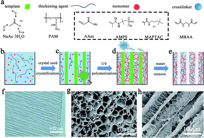
According to these pioneering works, we designed an optimized polymer gel electrolyte via “hot ice” template alignment and polyampholyte doping. The gel electrolyte with aligned micrometer-sized pores was prepared using a “hot ice” template (Fig. 1). The water precursor contained five components (Fig. 1a): distilled water, 0.0–4.0 wt% thickening agent (polyacrylamide, PAM), 15 wt% monomer (acrylamide, AAm), 0.045 wt% crosslinking agent (N,N-methylene bisacrylamide, MBAA) and 0.2 wt% initiator (diethoxy acetophenone, DEAP). At first, excessive sodium acetate (NaAc) was mixed with the previous precursor solution at 60 °C with an 82![[thin space (1/6-em)]](https://www.rsc.org/images/entities/char_2009.gif) :
:![[thin space (1/6-em)]](https://www.rsc.org/images/entities/char_2009.gif) 100 weight ratio (Fig. 1b). The mixture was then cooled to room temperature, forming a supersaturated NaAc solution. Crystallization of the supersaturated salt solution was initiated by the surface seeding of a NaAc·3H2O crystal, which produced an extensive rod-like “hot ice” from the contacted surface to the bottom (Fig. 1c; Video S1, ESI†). The hydrogel formed around the rod-like “hot ice” template after placing the mixture under UV irradiation (Fig. 1d). Following this, the “hot ice” template was removed from the hydrogel by washing it several times with distilled water, thereby forming a hydrogel with an aligned porous structure (Fig. 1e). The controllable pore sizes of the aligned hydrogel can be determined by examining the “hot ice” template sizes at various PAM concentrations with adjustable viscosity. In order to further improve the electrochemical properties, an aligned gel electrolyte composed of 5 wt% AAm and amphoteric monomers, 5 wt% 2-acrylamido-2-methyl propane sulfonic acid (AMPS) and 5 wt% (3-methacrylamidipropyl) trimethyl ammonium chloride (MAPTAC), was also prepared and investigated. As a control experiment, a normal hydrogel without an aligned porous structure was prepared too. All washed hydrogels were finally soaked in 1 M (NH4)2SO4 solution for several days before their application. The three hydrogel groups were recorded as “aligned-AAm,” “aligned-PA,” and “non-aligned” hydrogels. The mass fractions of the PAM solution were also used to further distinguish the various hydrogel samples.
100 weight ratio (Fig. 1b). The mixture was then cooled to room temperature, forming a supersaturated NaAc solution. Crystallization of the supersaturated salt solution was initiated by the surface seeding of a NaAc·3H2O crystal, which produced an extensive rod-like “hot ice” from the contacted surface to the bottom (Fig. 1c; Video S1, ESI†). The hydrogel formed around the rod-like “hot ice” template after placing the mixture under UV irradiation (Fig. 1d). Following this, the “hot ice” template was removed from the hydrogel by washing it several times with distilled water, thereby forming a hydrogel with an aligned porous structure (Fig. 1e). The controllable pore sizes of the aligned hydrogel can be determined by examining the “hot ice” template sizes at various PAM concentrations with adjustable viscosity. In order to further improve the electrochemical properties, an aligned gel electrolyte composed of 5 wt% AAm and amphoteric monomers, 5 wt% 2-acrylamido-2-methyl propane sulfonic acid (AMPS) and 5 wt% (3-methacrylamidipropyl) trimethyl ammonium chloride (MAPTAC), was also prepared and investigated. As a control experiment, a normal hydrogel without an aligned porous structure was prepared too. All washed hydrogels were finally soaked in 1 M (NH4)2SO4 solution for several days before their application. The three hydrogel groups were recorded as “aligned-AAm,” “aligned-PA,” and “non-aligned” hydrogels. The mass fractions of the PAM solution were also used to further distinguish the various hydrogel samples.
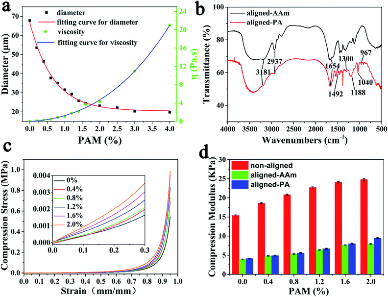
The “hot ice” template can form an aligned structure in the hydrogel, and the viscosity and the resultant pore size can be adjusted by altering the amount of PAM thickening agent (Fig. S4, ESI†). According to crystal growth theory, the viscosity of a supersaturated solution is inversely proportional to the crystal growth rate and diameter. The measured correlation of the PAM concentration with crystal size and intrinsic viscosity is shown in Fig. 2a. The diameter of the NaAc·3H2O crystals correspondingly decreased from 68 to 19 μm on increasing the PAM concentration from 0 wt% to 4 wt%. The regular NaAc·3H2O crystals in the aligned-AAm-2 wt% hydrogel are shown in the optical microscope image in Fig. 1f and the scanning electron microscope (SEM) images in Fig. S1a (ESI†). The needle-like crystal templates formed a parallel arrangement with roughly 23 μm diameter, as shown by optical microscopy (ESI, Fig. S2†). As shown in Fig. 1g and h, the aligned hydrogel after template removal has a roughly 50 μm pore size, which is significantly larger than that of the template due to the swelling effect (Fig. S5, ESI†). Accordingly, the largest pores (about 150 μm) were discovered in the aligned hydrogel with a PAM concentration of 0 wt% (Fig. S3, ESI†).
Polyampholyte doping within the aligned polymer gel electrolyte was achieved via the simple copolymerization of AAm, AMPS and MAPTAC. The coexistence of positive and negative monomers within our polymer hydrogel was proven by the FTIR spectra in Fig. 2b. The characteristic peaks of polyacrylamide can be found in the FTIR results of the aligned-AAm and the aligned-PA gels, including the absorption peaks at 1660 cm−1 for C![[double bond, length as m-dash]](https://www.rsc.org/images/entities/char_e001.gif) O, 2925 cm−1 for –CH2– and 3181 cm−1 for –NH2.39 Compared with the aligned-AAm sample, the FTIR of the aligned-PA gel revealed the successful modification of polyampholytes. The peak at 1040 cm−1 corresponds to the stretching signal of –SO3−,40 and the peaks at 1188 and 1300 cm−1 correlate with symmetric stretching and asymmetrical stretching S
O, 2925 cm−1 for –CH2– and 3181 cm−1 for –NH2.39 Compared with the aligned-AAm sample, the FTIR of the aligned-PA gel revealed the successful modification of polyampholytes. The peak at 1040 cm−1 corresponds to the stretching signal of –SO3−,40 and the peaks at 1188 and 1300 cm−1 correlate with symmetric stretching and asymmetrical stretching S![[double bond, length as m-dash]](https://www.rsc.org/images/entities/char_e001.gif) O vibrations.41,42 The absorption peaks at 1492 and 967 cm−1 coincide with the methyl groups of the quaternary ammonium and –N+(CH3)3 stretching vibrations,43 respectively.
O vibrations.41,42 The absorption peaks at 1492 and 967 cm−1 coincide with the methyl groups of the quaternary ammonium and –N+(CH3)3 stretching vibrations,43 respectively.
The compressive modulus of the aligned hydrogel was a little lower than that of the non-aligned hydrogel, but much higher than that of the commonly used PVA/H3PO4 gel electrolytes (Fig. S7, ESI†). Fig. 2d and S6 (ESI†) show that the modulus of the aligned hydrogels remained at about 30–40% relative to the non-aligned one due to the existence of large pores. The mechanical properties of the aligned-PA hydrogel electrolytes with different PAM concentrations are displayed in Fig. 2c. With the addition of PAM from 0 wt% to 2 wt%, the compressive strength of the aligned-PA hydrogel increased from 0.55 to 0.98 MPa at 95% strain due to the reinforcement effect from the thickening agent PAM. At the same time, the modulus of the aligned-PA hydrogel is slightly larger than that of the aligned-AAm hydrogel due to electrostatic interactions.
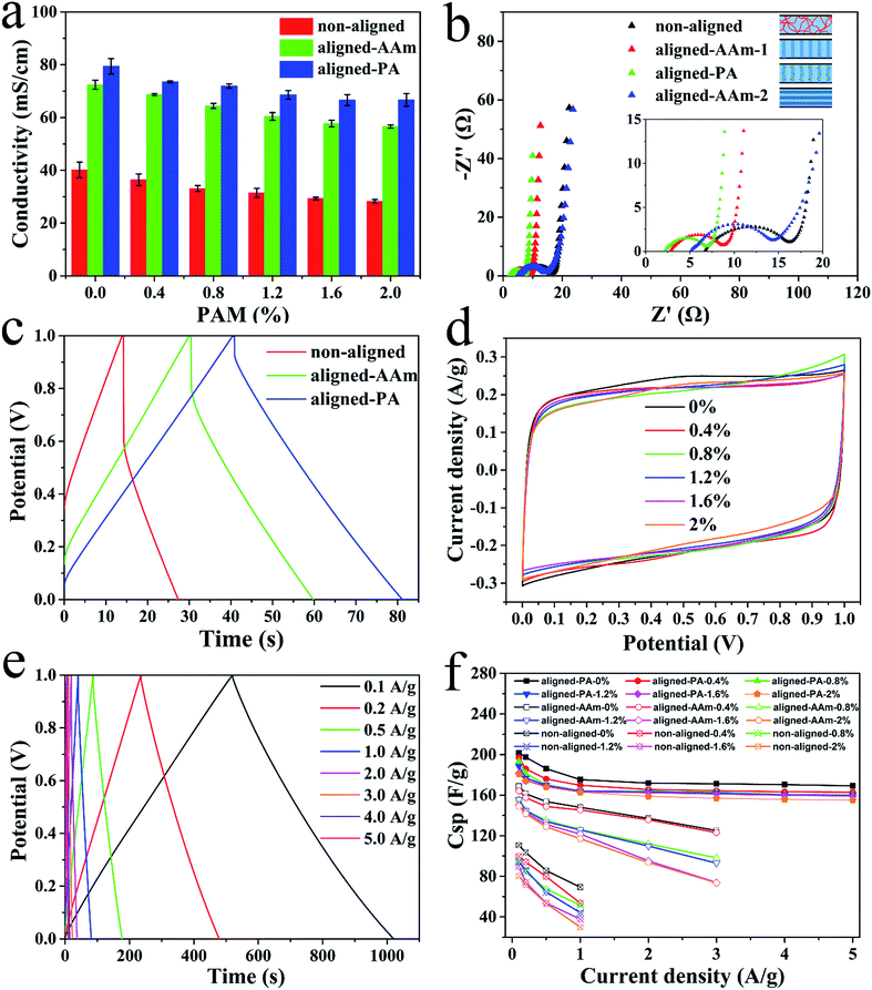
Prior to the application of the electrolytes in supercapacitors, various hydrogels were sliced vertically into 0.3 mm thick pieces using a blade, and then soaked in 1 M (NH4)2SO4 solution for several days before use. The ionic conductivity was determined by using electrochemical impedance spectroscopy tests (Fig. S8, ESI†). Fig. 3a shows the ionic conductivities of various types of electrolytes. The ionic conductivities of the electrolytes with an aligned porous structure in the vertical direction (55–70 mS cm−1) are greater than those of the non-aligned electrolytes (30–40 mS cm−1). In the parallel direction, the ionic conductivity (47.3 mS cm−1) is close to that of the non-aligned one. The anisotropic character and higher ionic conductivity of the aligned electrolytes are both ascribed to the liquid ionic channels within the large vertical pores. The increased PAM amount slightly decreased the ionic conductivity of the aligned gel due to the decreased pore size. The resistance (R) of porous gels can be determined using the following equation:17
| R = τρl/A | (1) |
Excellent ionic conductivity provides a basis for supercapacitor performance. The final electrochemical performance of the various gel electrolytes was measured using an assembled sandwich-type supercapacitor with commercial activated carbon powder (YP 80F) as the electrodes. As a result, the aligned-PA based supercapacitor shows the highest discharge capacitance compared to the other supercapacitors in Fig. 3c, S11 and S12 (ESI†). The discharge capacitance value of the aligned-PA based supercapacitor is roughly 3.0 and 1.4 times that of the non-aligned and aligned-AAm based supercapacitor, respectively. The electrochemical performance of the aligned-PA based supercapacitors with various size pores is shown in Fig. 3d. The cyclic voltammetry curves approximate an ideal rectangle at 5 mV s−1, and the specific capacitance decreases slightly with increasing PAM concentration due to influence of the pore size and ionic conductivity. The measured Nyquist plots of the various electrolytes in Fig. 3b confirmed the highest electrochemical performance and anisotropic character of the aligned-PA gel based supercapacitors. The bulk resistance (Rs) and charge transfer resistance (Rct) are mainly attributed to the gel electrolytes and the interface properties between the electrolytes and the electrodes, respectively. The aligned-PA based supercapacitor has the smallest Rs of 2.2 Ω in the vertical direction, lower than that of the non-aligned based supercapacitor (6.7 Ω) and the aligned-AAm based supercapacitors, 2.8 Ω (aligned-AAm-1, pores aligned in the vertical direction), and 5.2 Ω (aligned-AAm-2, pores aligned in the parallel direction). Besides, the Rct values of the aligned-PA, aligned-AAm-1, aligned-AAm-2 and non-aligned gel based supercapacitors were 4.7 Ω, 5.9 Ω, 9.3 Ω and 9.5 Ω, respectively. All of the evidence leads to the conclusion that aligned pore designs can improve the supercapacitor performance and polyampholyte doping can further lead to superior electrochemical performance.
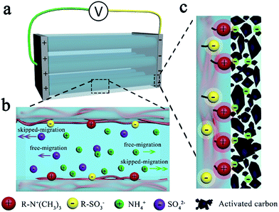
Therefore, the aligned-PA based supercapacitor was selected for further research. The galvanostatic charge–discharge curves of the supercapacitors containing the aligned-PA-0 wt% gel electrolyte approximate an isosceles triangle (Fig. 3e), and a high discharge capacitance of 201.5 F g−1 is achieved at a current density of 0.1 A g−1. Amazingly, this value is even greater than that of the supercapacitor with a 1 M (NH4)2SO4 solution electrolyte of 159.0 F g−1 (Fig. S13b, ESI†). The ultrahigh electrochemical performance of the aligned-PA electrolytes is explained as follows. On the one hand, the high ionic conductivity derived from the aligned pores provides a basis for great improvement in the capacitance performance. As direct evidence of this, the value of the aligned-AAm based supercapacitor is about 160 F g−1 (Fig. S12, ESI†), analogous to that of the liquid supercapacitor. On the other hand, there is strong adhesion between the aligned-PA gel electrolyte and the electrodes (Fig. S14, ESI†) due to the ionic bonds between the polyampholyte and the negatively charged (or positively charged) electrode material after charging (Fig. 4c), leading to lower interface resistance and further higher discharge capacitance. Gong's group proved the self-adjustable adhesion of polyampholyte materials due to alternative coulombic interactions.36 The result that the aligned-PA based supercapacitor has the smallest IR drop (Fig. 3c) and the lowest internal resistance also confirmed our hypothesis. In general, it is the reduced internal resistance stemming from the improved ionic conductivity of the electrolyte and the generated strong adhesion between the electrolyte and the electrodes that optimize the performance of the ultrahigh-capacity supercapacitor.
Furthermore, the aligned-PA based supercapacitors also perform better than their rivals in maintaining their capacitance at higher current densities (Fig. 3f). For example, the supercapacitor with the aligned-PA gel electrolyte reached a high specific capacitance with a rate capacity of only ∼15% capacitance loss as the current density increased from 0.1 to 5 A g−1. Meanwhile, the rate loss of the non-aligned and aligned-AAm based supercapacitors exceeded 20% and 12% from 0.1 to 1 A g−1, respectively. Therefore, the aligned-PA electrolyte can significantly enhance the capacitance and rate capacity of the supercapacitor.
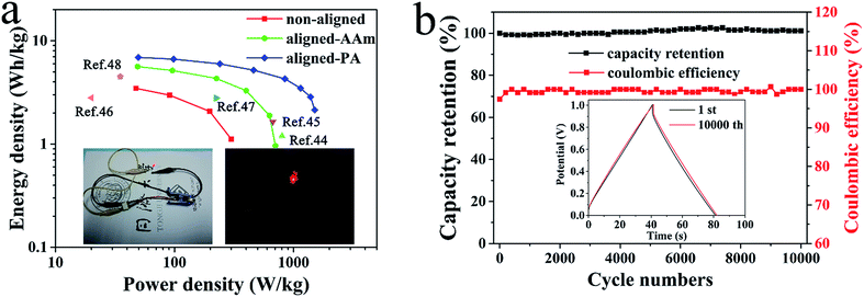
For practical application in real life, we investigated the energy efficiency and cycling stability of the solid-state supercapacitors. The energy and power density were calculated from their galvanostatic charge–discharge curves. As shown in Fig. 5a, the aligned-PA-0 wt% based supercapacitor presents an energy density of 6.9 W h kg−1 at a power density of 50 W kg−1, which is much higher than the 5.6 W h kg−1 and 3.5 W h kg−1 energy densities of the supercapacitors with the aligned-AAm electrolyte and non-aligned electrolyte, respectively. Compared to some previous reported aqueous gel electrolytes,44–48 our supercapacitors also show competitive and even greater performance. In addition, a red light-emitting diode (LED) bulb (1.8–2.0 V) was successfully lit by two aligned-PA based supercapacitors connected in series (Video S2, ESI†), suggesting that the material would be a promising candidate in energy-efficient storage devices. The cycling stability of the aligned-PA based supercapacitors was excellent during their charging and discharging cycles, which is also one of the important indexes for practical applications. After 10![[thin space (1/6-em)]](https://www.rsc.org/images/entities/char_2009.gif) 000 cycles at 1 A g−1, the capacity retention of the aligned-PA-0 wt% based supercapacitor stabilized at around 101.1% (Fig. 5b). Additionally, the coulombic efficiency was maintained at about 100% as a result of the long-term stability of the aligned electrolyte. The cycling stability confirmed the possibility of practical application in flexible devices.
000 cycles at 1 A g−1, the capacity retention of the aligned-PA-0 wt% based supercapacitor stabilized at around 101.1% (Fig. 5b). Additionally, the coulombic efficiency was maintained at about 100% as a result of the long-term stability of the aligned electrolyte. The cycling stability confirmed the possibility of practical application in flexible devices.
Conclusions
Our hydrogel electrolytes were designed and optimized by “hot-ice” alignment and polyampholyte doping. Our electrolytes exhibit a significantly higher ionic conductivity due to the vertical liquid ion channels. The ultrahigh discharge capacitance of 201.5 F g−1 at 0.1 A g−1 of the aligned-PA gel based supercapacitor is about 2 times that of the non-aligned one due to the charging-adjusted adhesion of the polyampholyte-doped electrolytes and the resulting lower interface resistance. Their steady capacitance remained at about 101.1% after undergoing 10![[thin space (1/6-em)]](https://www.rsc.org/images/entities/char_2009.gif) 000 charge–discharge cycles. Therefore, our electrolyte materials, with optimized ionic mobility and mechanical strength, have great potential for application as integrated electrolytes and separators in flexible/wearable electronic devices.
000 charge–discharge cycles. Therefore, our electrolyte materials, with optimized ionic mobility and mechanical strength, have great potential for application as integrated electrolytes and separators in flexible/wearable electronic devices.
Conflicts of interest
There are no conflicts to declare.Acknowledgements
This work was supported by the National Natural Science Foundation of China (No. 51473123), and the National Key Research and Development Program (No. 2016YFA0100800).References
- P. Simon and Y. Gogotsi, Nat. Mater., 2008, 7, 845–854 CrossRef CAS PubMed.
- X. H. Liu, C. Y. Yin, J. Yang, M. Y. Liang, J. J. Wei, Z. Y. Zhang, H. L. Wang and Q. G. Wang, J. Mater. Chem. A, 2016, 4, 17933–17938 CAS.
- L. Y. Liu, B. S. Shen, D. Jiang, R. S. Guo, L. B. Kong and X. B. Yan, Adv. Energy Mater., 2016, 6, 1600763 CrossRef.
- X. B. Cheng, M. Q. Zhao, C. Chen, A. Pentecost, K. Maleski, T. Mathis, X. Q. Zhang, Q. Zhang, J. J. Jiang and Y. Gogotsi, Nat. Commun., 2017, 8, 336 CrossRef PubMed.
- L. Li, S. M. Chen, X. B. Wang, Y. Bando and D. Golberg, Energy Environ. Sci., 2012, 5, 6040–6046 CAS.
- X. F. Li, J. Liu, M. N. Banis, A. Lushington, R. Y. Li, M. Cai and X. L. Sun, Energy Environ. Sci., 2014, 7, 768–778 CAS.
- B. Anothumakkool, A. T. A. Torris, S. Veeliyath, V. Vijayakumar, M. V. Badiger and S. Kurungot, ACS Appl. Mater. Interfaces, 2016, 8, 1233–1241 CAS.
- X. H. Lu, M. H. Yu, G. M. Wang, Y. X. Tong and Y. Li, Energy Environ. Sci., 2014, 7, 2160–2181 Search PubMed.
- P. H. Yang and W. J. Mai, Nano Energy, 2014, 8, 274–290 CrossRef CAS.
- X. F. Wang, X. H. Lu, B. Liu, D. Chen, Y. X. Tong and G. Z. Shen, Adv. Mater., 2014, 26, 4763–4782 CrossRef CAS PubMed.
- N. Chen, Y. J. Dai, Y. Xing, L. L. Wang, C. Guo, R. J. Chen, S. J. Guo and F. Wu, Energy Environ. Sci., 2017, 10, 1660–1667 CAS.
- Y. Isshiki, M. Nakamura, S. Tabata, K. Dokko and M. Watanabe, Polym. Adv. Technol., 2011, 22, 1254–1260 CrossRef CAS.
- Z. B. Yang, J. Deng, X. L. Chen, J. Ren and H. S. Peng, Angew. Chem., Int. Ed., 2013, 52, 13453–13457 CrossRef CAS PubMed.
- D. Kim, G. Shin, Y. J. Kang, W. Kim and J. S. Ha, ACS Nano, 2013, 7, 7975–7982 CrossRef CAS PubMed.
- K. Wang, X. Zhang, C. Li, X. Z. Sun, Q. H. Meng, Y. W. Ma and Z. X. Wei, Adv. Mater., 2015, 27, 7451–7457 CrossRef CAS PubMed.
- W. Liu, M. S. Song, B. Kong and Y. Cui, Adv. Mater., 2017, 29, 1603436 CrossRef PubMed.
- X. H. Liu, D. B. Wu, H. L. Wang and Q. G. Wang, Adv. Mater., 2014, 26, 4370–4375 CrossRef CAS PubMed.
- Y. Huang, M. Zhong, Y. Huang, M. S. Zhu, Z. X. Pei, Z. F. Wang, Q. Xue, X. M. Xie and C. Y. Zhi, Nat. Commun., 2015, 6, 10310 CrossRef CAS PubMed.
- Y. Huang, M. Zhong, F. K. Shi, X. Y. Liu, Z. J. Tang, Y. K. Wang, Y. Huang, H. Q. Hou, X. M. Xie and C. Y. Zhi, Angew. Chem., Int. Ed., 2017, 56, 9141–9145 CrossRef CAS PubMed.
- S. Y. Lu, C. M. Gao, X. B. Xu, X. Bai, H. G. Duan, N. N. Gao, C. Feng, Y. Xiong and M. Z. Liu, ACS Appl. Mater. Interfaces, 2015, 7, 13029–13037 CAS.
- U. G. K. Wegst, H. Bai, E. Saiz, A. P. Tomsia and R. O. Ritchie, Nat. Mater., 2015, 14, 23–36 CrossRef CAS PubMed.
- T. Chen, L. B. Qiu, H. G. Kia, Z. B. Yang and H. S. Peng, Adv. Mater., 2012, 24, 4623–4628 CrossRef CAS PubMed.
- L. Qian and H. F. Zhang, J. Chem. Technol. Biotechnol., 2011, 86, 172–184 CrossRef CAS.
- S. R. Quake and A. Scherer, Science, 2000, 290, 1536–1540 CrossRef CAS PubMed.
- A. Walcarius, E. Sibottier, M. Etienne and J. Ghanbaja, Nat. Mater., 2007, 6, 602–608 CrossRef CAS PubMed.
- E. Salnikov, M. Rosay, S. Pawsey, O. Ouari, P. Tordo and B. Bechinger, J. Am. Chem. Soc., 2010, 132, 5940–5941 CrossRef CAS PubMed.
- H. W. Gu, R. K. Zheng, X. X. Zhang and B. Xu, Adv. Mater., 2004, 16, 1356–1359 CrossRef CAS.
- H. Zhang and A. I. Cooper, Adv. Mater., 2007, 19, 1529–1533 CrossRef CAS.
- J. T. Zhu, J. W. Wang, Q. Y. Liu, Y. H. Liu, L. Wang, C. C. He and H. L. Wang, J. Mater. Chem. B, 2013, 1, 978–986 RSC.
- H. F. Zhang, I. Hussain, M. Brust, M. F. Butler, S. P. Rannard and A. I. Cooper, Nat. Mater., 2005, 4, 787–793 CrossRef CAS PubMed.
- H. Bai, A. Polini, B. Delattre and A. P. Tomsia, Chem. Mater., 2013, 25, 4551–4556 CrossRef CAS PubMed.
- H. Bai, D. Wang, B. Delattre, W. W. Gao, J. De Coninck, S. Li and A. P. Tomsia, Acta Biomater., 2015, 20, 113–119 CrossRef CAS PubMed.
- M. Yang, N. F. Zhao, Y. Cui, W. W. Gao, Q. Zhao, C. Gao, H. Bai and T. Xie, ACS Nano, 2017, 11, 6817–6824 CrossRef CAS PubMed.
- X. H. Liu, B. F. Wang, Z. L. Jin, H. L. Wang and Q. G. Wang, J. Mater. Chem. A, 2015, 3, 15408–15412 CAS.
- H. J. He, M. Y. Liu, J. J. Wei, P. Chen, S. L. Wang and Q. G. Wang, Adv. Healthcare Mater., 2016, 5, 648–652 CrossRef CAS PubMed.
- C. K. Roy, H. L. Guo, T. L. Sun, A. Bin Ihsan, T. Kurokawa, M. Takahata, T. Nonoyama, T. Nakajima and J. P. Gong, Adv. Mater., 2015, 27, 7344–7348 CrossRef CAS PubMed.
- F. B. Zhu, L. B. Cheng, J. Yin, Z. L. Wu, J. Qian, J. Z. Fu and Q. Zheng, ACS Appl. Mater. Interfaces, 2016, 8, 31304–31310 CAS.
- X. Peng, H. L. Liu, Q. Yin, J. C. Wu, P. Z. Chen, G. Z. Zhang, G. M. Liu, C. Z. Wu and Y. Xie, Nat. Commun., 2016, 7, 11782 CrossRef CAS PubMed.
- T. Li, Y. Yuan, B. Hong, H. Cao, K. Zhang, Y. Q. Lai, Y. X. Liu and Z. X. Huang, Electrochim. Acta, 2017, 244, 192–198 CrossRef CAS.
- L. P. Zhang, J. Wang, C. H. Ni, Y. A. Zhang and G. Shi, Mater. Sci. Eng., C, 2016, 58, 724–729 CrossRef CAS PubMed.
- Y. Y. Zhang, Y. M. Li and W. G. Liu, Adv. Funct. Mater., 2015, 25, 471–480 CrossRef CAS.
- L. L. Zhang, H. J. Gao and Y. W. Liao, React. Funct. Polym., 2016, 104, 53–61 CrossRef CAS.
- X. Li, H. L. Zheng, B. Y. Gao, Y. J. Sun, B. Z. Liu and C. L. Zhao, Chemosphere, 2017, 167, 71–81 CrossRef CAS PubMed.
- Z. Q. Niu, H. B. Dong, B. W. Zhu, J. Z. Li, H. H. Hng, W. Y. Zhou, X. D. Chen and S. S. Xie, Adv. Mater., 2013, 25, 1058–1064 CrossRef CAS PubMed.
- S. Y. Wang, B. Pei, X. S. Zhao and R. A. W. Dryfe, Nano Energy, 2013, 2, 530–536 CrossRef CAS.
- D. Antiohos, G. Folkes, P. Sherrell, S. Ashraf, G. G. Wallace, P. Aitchison, A. T. Harris, J. Chen and A. I. Minett, J. Mater. Chem., 2011, 21, 15987–15994 RSC.
- Z. K. Wang and Q. M. Pan, Adv. Funct. Mater., 2017, 27, 1700690 CrossRef.
- Q. Q. Tang, M. M. Chen, G. C. Wang, H. Bao and P. Saha, J. Power Sources, 2015, 284, 400–408 CrossRef CAS.
Footnote |
| † Electronic supplementary information (ESI) available. See DOI: 10.1039/c7ta09616j |
| This journal is © The Royal Society of Chemistry 2018 |

