 Open Access Article
Creative Commons Attribution 3.0 Unported Licence
Graphene and graphene-like materials in biomass conversion: paving the way to the future
Vijay Kumar
Das
a,
Zinaida B.
Shifrina
 b and
Lyudmila M.
Bronstein
 *abc
*abc
aIndiana University, Department of Chemistry, 800 E. Kirkwood Av., Bloomington, IN 47405, USA. E-mail: lybronst@indiana.edu
bA.N. Nesmeyanov Institute of Organoelement Compounds, Russian Academy of Sciences, 28 Vavilov St., Moscow, 119991 Russia
cKing Abdulaziz University, Faculty of Science, Department of Physics, Jeddah, Saudi Arabia
First published on 14th November 2017
Abstract
Materials based on graphene and its derivatives have a dual relationship with biomass: (i) they can be synthesized using biomass or its platform chemicals and (ii) they can be employed as efficient catalysts or supports for nanoparticulate catalysts for biomass conversion. In this review article we discuss methods of catalyst synthesis using top-down and bottom-up approaches as well as different synthetic pathways where all or some catalyst components are prefabricated or the whole catalyst is prepared in situ from small molecules. We identify key factors influencing the efficiency of the catalysts formed and suggest our perspective for the development of this field.
1. Introduction
Biomass conversion plays a tremendous role in obtaining value-added chemicals and fuels from renewable sources without the use of petrochemicals. It is well known that oil and gas compositions can strongly vary depending on the place and method of their extraction. For biomass, these variations can be even more pronounced depending on the biomass source. The possible biomass sources were well-described in a recent review article, identifying lignocellulosic biomass as the most abundant. It includes three main components: 40–50% cellulose, 20–40% hemicellulose, and 20–30% lignin.1 Pyrolysis or hydrolysis of biomass leads to bio-oils, whose composition, in turn, can vary tremendously. Moreover, raw bio-oil must be upgraded to remove compounds such as phenols and furfurals which are easily polymerized. This creates a whole spectrum of different processes often requiring very different catalysts. An example of such processes is the catalytic oxidation of biomass derived intermediates such as glucose, 5-hydroxymethylfurfural (HMF), furfural, eugenol, isoeugenol, etc. to high value chemicals.2,3 The diversity of the starting materials puts a significant constraint on the development of catalysts for biomass processing. Considering the growing demand for energy and value-added chemicals obtained from renewable sources, the catalysts developed for these numerous processes need to be efficient, selective, robust, and stable. Moreover, their production should be easily scalable to gram or kilogram quantities from the more common milligram quantities used in laboratory settings.The catalysts used in the biomass conversion include (but are not limited to) metal oxides with and without metal nanoparticles (NPs), zeolites, carbon based catalysts with metal NPs, solid acids, etc.4–9 The recent development of graphene based catalysts opened a new possibility in the exploration of such catalysts in biomass conversion. Moreover, graphene based supports can be synthesized from biomass and its platform chemicals, making it a dual purpose material.
Despite the fact that graphene was first obtained by exfoliation only in 2004,11 its remarkable properties and great utilization potential prompted an explosion of new chemical routes to synthesize graphene and graphene-like materials. However, the synthesis of quality graphene and its derivatives has always remained a challenge. All synthetic methods can be classified into two approaches: (i) top-down and (ii) bottom-up. The top-down approach is realized when graphite is exfoliated into graphene layers via overcoming van der Waals forces between the layers using oxidation or other treatments. The surface defects occurring during sheet separation lead to their re-agglomeration later and low yields, representing a considerable limitation of this approach. On the other hand, this approach is good for manufacturing graphene nanoribbons, nanoplatelets, etc. in large quantities (Fig. 1).10,12,13
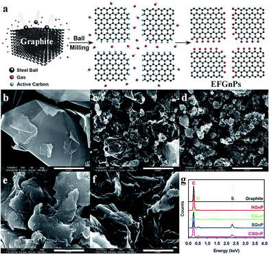 | ||
| Fig. 1 (a) Schematic representation of the mechanochemical reaction between in situ generated active carbon species and reactant gases in a sealed ball-mill crusher. The cracking of graphite by ball milling in the presence of corresponding gases and subsequent exposure to air moisture resulted in the formation of edge-selectively functionalized graphene nanoplates (EFGnPs). The red balls represent reactant gases such as hydrogen, carbon dioxide, sulfur trioxide, and air moisture (oxygen and moisture). SEM images: (b) pristine graphite; (c) hydrogen-graphene nanoplates (GnP); (d) carboxylic acid-GnP; (e) sulfonic acid-GnP; and (f) carboxylic acid/sulfonic acid-GnP. Scale bars are 1 μm. (g) EDX spectra of the pristine graphite and EFGnPs. Reprinted with permission from ref. 10. Copyright (2013) American Chemical Society. | ||
A combination of top-down and bottom-up approaches is realized when biomass feedstocks are first subjected to pyrolysis (top-down) and then the pyrolysis product is converted to graphene or its derivatives (bottom-up).14 Several elegant methods to form nonfunctional or functionalized defect-free graphene sheets and ribbons using a bottom-up approach have been developed,15–18 but these methods normally include multiple steps, making their practical application difficult. A more robust bottom-up approach is the conversion of biomass derivatives, for example, glucose, to graphene.19,20 The biomass based approaches for the synthesis of graphene based supports and catalysts pave the way for making these catalysts environmentally friendly and widely available.
The issue of possible graphene toxicity to humans has been raised in the recent review article.1 However, several latest reports indicate minimal toxicity of graphene based materials to lung tissue.21–23 Moreover, graphene based materials are being actively studied as potential cancer treatment agents with minimized toxicity for healthy cells. For example, few-layer graphene (FLG) was reported to kill cancer cells, showing neither toxicity nor activation effects on other immune cells unlike regular chemotherapy.24 These data allow us to propose that graphene based catalysts can be considered safe for catalytic applications, unless contradictory data come to light.
Taking into account two preceding review articles (published in 2014 (ref. 25) and 2015 (ref. 1)), in this review we focus mainly on identifying the key features of graphene, graphene oxide (GO) and reduced graphene oxide (RGO) based catalysts for various processes of biomass conversion in order to determine which catalyst types are the most promising and how intelligent catalyst design can revolutionize this field. Despite numerous review articles describing the structure of graphene and its derivatives, for the sake of clarity of this review, we will discuss the features of different types of graphene based materials pertinent to catalysis and major methods of their synthesis. In the successive sections we will briefly discuss graphene based materials as catalysts in acid or base catalysis, and subsequently, in greater detail, we will review catalysts containing metal and metal compound NPs along with graphene or its derivatives. The question we are raising here is, what does the future hold? In the Concluding remarks we will address this question.
2. Key structural features of graphene, GO, and RGO pertinent to catalysis
Graphene, an allotrope of carbon, is a flat nanolayer (0.35–1.6 nm in thickness) of trigonally bonded sp2 hybridized carbon atoms firmly packed into a two dimensional hexagonal honeycomb lattice (Fig. 2).26–28 It is noteworthy that its aromaticity is different from the aromaticity of standard aromatic compounds such as benzene, coronene, etc. Aromaticity in graphene is local with two π-electrons delocalized over every hexagonal ring.29 It results in a very tightly packed and strongly bonded network of carbon atoms within the layer. Because the carbon–carbon bonds are short and strong (three per carbon atom), it allows for a very high tensile strength (300 times that of steel). At the same time, graphene is a light, low density material. The π electrons are mobile throughout the layer, generating electrical conduction if a potential difference is applied. The ‘large scale’ delocalization bestows chemical stability to graphene.30 Additionally, due to this delocalized system, graphene is unsaturated and atoms can be added to its structure.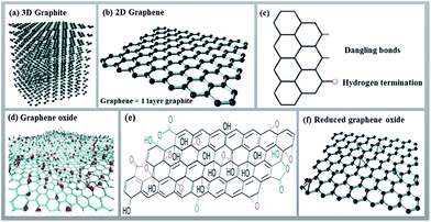 | ||
| Fig. 2 Structures of 3D graphite (a), 2D graphene and its edge (b and c), graphene oxide (d and e) and reduced graphene oxide (f). Panels (a), (b), and (f) are reprinted with permission from ref. 28. Copyright (2016) Elsevier. Panels (c) and (d) are reprinted with permission from ref. 26. Copyright (2013) Royal Society of Chemistry. Panel (e) is reprinted with permission from ref. 27. Copyright (2009) Nature Publishing Group. | ||
Through the oxidation of graphite (a 3D carbon material) using strong oxidizing agents, abundant oxygen containing functionalities such as hydroxyl, carboxyl, and epoxy are introduced on both the basal planes and edges of a graphite structure. These groups expand the layer separation and make the material hydrophilic. This feature allows for exfoliation of graphite oxide (a multilayer system) in water using sonication, eventually creating single or a few layers thick functionalized graphene called graphene oxide (GO). The crucial advantage of GO is that it can be easily dispersed in water. As for electrical conductivity, GO can be considered an electrical insulator due to the disruption of its sp2 bonding networks. In order to restore the honeycomb hexagonal lattice along with the electrical conductivity, the reduction of GO has to be accomplished using thermal, chemical or electrical treatments. RGO is more difficult to disperse because of its propensity to form aggregates, but it still retains some oxygen functionalities which allow for better solubility (although limited to aprotic solvents) than that of native graphene. RGO reveals properties between those of graphene and GO, with the reduction process strongly influencing these properties. In large scale operations, RGO is a more obvious choice compared to graphene, due to the relative ease of obtaining sufficient quantities of the desired quality levels.31
GO, RGO and their doped analogues are often called chemically modified graphenes (CMGs). Due to their numerous functionalities, comparatively low cost, high mechanical strength, and optical and electronic stability, CMGs are appealing alternatives to conventional acidic catalysts and supports for the active catalyst phase.32 Graphene has a theoretical specific surface area of about 2600 m2 g−1, which is nearly twice as high as the value for single-walled carbon nanotubes (CNTs) and considerably higher than those of multi-walled CNTs, most carbon blacks and activated carbons,33 which makes it an ideal candidate for processes involving adsorption or surface reactions. Thus, the typical structural features of graphene make it possible to use it as a two-dimensional catalyst or support in catalysis.34 Furthermore, the locally conjugated structure endows graphene with better capacity to adsorb substrates in the catalytic reactions.35 Also, graphene and its derivatives contain no metallic impurities that are inevitably present in CNTs and which often obstruct the catalytic performance of CNT based materials in chemical reactions.36 Finally, the greater degree of electron mobility of graphene based materials promotes electron transfer during chemical reactions enhancing their catalytic activity.37 Consequently, graphene and its derivatives create a perfect foundation for anchoring nanomaterials and creating a robust interaction between themselves and the active catalytic sites. In turn, the synergistic effect between active sites and graphene stimulates the reactivity. The graphene based template is believed to stabilize active catalytic sites and prevent wandering of nanosized metals from the surface under harsh reaction conditions.
Because of its chemical inertness and zero band gap, pristine graphene (in solid-state form) synthesized by micromechanical exfoliation, epitaxial growth and chemical vapour deposition is not a promising candidate for catalysis.38 The catalytic action of pristine graphene, however, can be enhanced by doping with heteroatoms like nitrogen, boron or sulfur to generate large numbers of active sites.39,40
3. Synthesis of CMGs
As has been discussed in the Introduction, two general approaches, top-down and bottom-up, are used for CMG synthesis. In the top-down approach, GO is synthesized by exfoliation of graphite using strong oxidizing agents and then is reduced (using various reducing agents such as hydrazine,41L-ascorbic acid,42 nature based plant extracts,31etc.) to form RGO. When GO is reduced to RGO, the solubility becomes limited to aprotic solvents (DMF, N-methyl-2-pyrrolidone). Reduction of GO combined with nitrogen doping can be realized upon reaction with melamine,43 NH3,44,45etc. and allows for improved solubility due to pyridine moieties.The first synthesis of GO in modern history was reported by Hummers in 1958 using harsh conditions.46 Considering that this method results in a starting material for RGO, in recent years there has been a significant spike in interest in GO synthesis, leading to the development of several improved procedures where less harsh conditions are explored for graphite exfoliation.47,48 It is noteworthy that GO can be easily prepared in quantities of several grams, while reduction is normally carried out in diluted solutions, so the RGO yields are lower.
Over the past few years, biomass feedstocks have become popular benign precursors for carbon based catalysts or catalyst supports because they are inexpensive and readily obtainable in high quality and quantity. They are also available in abundant morphological and structural varieties, containing multiple elements.49 Lignocellulose has been used as a source of graphene or graphene-like nanostructures, presenting a green chemistry top-down approach.50 The production of high quality graphene from biomass opens new horizons for the conversion of waste into high value products. In light of this, Tour and co-workers grew graphene from food, insects, and waste by chemical vapour deposition (CVD) (Fig. 3).51 To accomplish this, a carbon source was placed on top of a Cu foil, and the foil was introduced into a 1050 °C tube furnace. They developed a cheap approach using six easily obtained, low or negatively valued raw carbon-containing materials (cookies, chocolate, grass, plastics, roaches, and dog feces) used without further purification to grow graphene directly on the reverse side of a Cu foil at 1050 °C under H2/Ar flow.
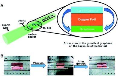 | ||
| Fig. 3 (A) Diagram of the experimental apparatus for the growth of graphene from food, insects, or waste in a tube furnace. On the left, the Cu foil with the carbon source contained in a quartz boat is placed in the hot zone of the tube furnace. The growth is performed at 1050 °C under low pressure with a H2/Ar gas flow. On the right is a cross section that represents the formation of pristine graphene on the reverse side of the Cu substrate. (B) Growth of graphene from a cockroach leg. (a) One roach leg on top of the Cu foil. (b) Roach leg under vacuum. (c) Residue from the roach leg after annealing at 1050 °C for 15 min. The pristine graphene grew on the reverse side of the Cu film (not shown). Reprinted with permission from ref. 51. Copyright (2011) American Chemical Society. | ||
Zhou et al. prepared nitrogen doped porous graphene by applying KOH activation with eggplant followed by injecting ammonia under an Ar flow at high temperatures.52 Guo et al. pyrolyzed a solid-state mixture of Coprinus comatus biomass and melamine under a nitrogen atmosphere at 600 °C to obtain a nitrogen-doped biocarbon/graphene-like composite, graphitic carbon nitride, which acted as a self-sacrificing template.53 Wang and co-workers produced N-doped mesocellular graphene foam via a one-step pyrolysis of sludge flocs at 900 °C under a N2 atmosphere.54 Gao and co-workers synthesized a three-dimensional porous graphene-like material by using dried honeysuckles as a single precursor heated in a nitrogen atmosphere.55 This resulted in RGO doped with both N and S.
In a mixed bottom-up/top-down approach from a biomass derivative (glucose) and GO, hierarchical nitrogen-doped porous graphene/carbon (NPGC) composites were prepared by hydrothermal carbonization with KOH at 950 °C.56 The authors determined that this allows for a well-ordered 3D network structure, with nitrogen groups homogeneously dispersed in the material (Fig. 4).
 | ||
| Fig. 4 Schematic illustration of the preparation process for NPGC-950. Reprinted with permission from ref. 56. Copyright (2016) American Chemical Society. | ||
Apart from the above biomass sources, well-aligned graphene layers have been synthesized from poultry litter and wastewater biosolids,57Pinus kesiya sawdust,58 seaweed (Sargassum tenerrimum),59 nori biomass,60 bacterial cellulose/lignin,61 biomass residues of the olive oil industry,62 coconut shell,63 pine wood sawdust,64 soybean oil precursor,65 natural chitosan66 and glucose.67
Despite the fact that the synthesis of CMGs from biomass could result in unwanted impurities (along with the desired doping), the ubiquity and low cost of various biomass sources could be a deciding factor for choosing large scale methods to obtain CMGs.
4. GO/RGO catalysed biomass conversion
GO without any additional functionalization or functionalized with acidic groups has been employed as a catalyst for a number of biomass related processes. Several mechanisms could be identified which promote catalytic assistance by GO in addition to the inherent functional group influence. In a number of cases it is accompanied by the conversion of GO to RGO, with the latter most likely playing a crucial role in the process.68,69 The above assistance mechanisms include (i) self-assembly on the GO/RGO surface, (ii) formation of strong hydrogen bonds between the substrate and GO, and (iii) induced defect sites due to the incorporated functional groups. Below we illustrate these mechanisms for different biomass conversion processes.4.1. Self-assembly on the GO/RGO surface
Recently, Shi and co-workers reported the application of GO as a template as well as catalyst to carbonize egg proteins.70 Egg proteins were self-assembled on the surface of the GO sheets owing to their strong interactions, whereas impurities were dissolved in the residual solution. Wang et al. used GO as a carbocatalyst for the selective etherification of HMF to 5-oxy(bis-methylene)-2-furaldehyde (OBMF) in high yield (86%).71 The catalytic activity of GO in recycling declined slightly after the fifth cycle due to the loss of oxygen-containing functionalities which generated fewer active sites, revealing the importance of the GO functional groups.Yadav and co-workers first prepared a GO monolith using carbonization of a biomass derivative in the presence of a small amount of GO (as a structure directing agent) and then functionalized it with chlorosulfonic groups. This catalyst has shown activity in esterification reactions.72
4.2. Bonding between the substrate and GO
Prasad and co-workers reported the utility of GO in combination with simple sugars and choline chloride (Fig. 5) using ethyl lactate as the solvent for the simultaneous production of HMF and RGO nanosheets (96% recovery).69 In this process the solvent was recycled and reused after recovery of the products, an important approach from the viewpoint of green chemistry. It was found that chemical bonding between sugar and the GO carbon caused steric hindrance, preventing π–π stacking interactions among the GO sheets, thereby promoting the conversion of stacked GO to few-layer GO nanosheets and RGO. These interactions probably also facilitated the catalytic reaction.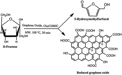 | ||
| Fig. 5 Simultaneous production of HMF and reduced graphene oxide from fructose promoted by graphene oxide using choline chloride and betaine hydrochloride as additives. Reprinted with permission from ref. 69. Copyright (2014) Royal Society of Chemistry. | ||
Hou and Zhu successfully synthesized HMF (87% yield) via dehydration of fructose in 90 vol% isopropanol-mediated DMSO solvent in the presence of GO (prepared by the Hummers' method).73 The authors determined that due to a small number of sulfonic groups and a large number of oxygen-containing functionalities, GO forms strong hydrogen bonds with fructose, allowing for a synergistic effect in providing high catalytic performance.
4.3. Induced defect sites due to incorporated functional groups
Acid or base catalysed biomass conversion widely employs GO based catalysts after proper functionalization. The hydroxyalkylation/alkylation (HAA) condensation of 2-methylfuran (2-MF) with carbonyl group containing compounds using an acid catalyst is a promising alternative to C–C coupling reactions for producing fuel precursors.74 In this regard, Dutta et al. reported the C–C coupling of 2-MF at its C5 position with biomass derived aldehydes and ketones through HAA, catalysed by improved GO (IGO) to yield C12–C21 fuel precursors in liquid form (95% yield) under mild reaction conditions.75 Herein, IGO was synthesized via Tour's method47 by surface modification of a parent graphitic framework with new functionalities such as epoxy, hydroxyl, carbonyl, and carboxyl groups. These functionalities contributed to the Brønsted acidity and hydrophilic/oxophilic properties of the material and induced beneficial oxidized defect sites enhancing the reactivity. The authors of this work found that IGO showed considerably higher activity compared to traditional zeolites and commercial GO. IGO was found to be recyclable and regained almost all of its activity upon regeneration.Considering that GO may carry multiple functional groups (–OH, –COOH, –SO3H, etc.), the question arises as to which groups are critical for the conversion of biomass and its derivatives. Zhu and co-workers demonstrated that SO3H groups were crucial for furfuryl alcohol (FAL) alcoholysis, while removal of hydroxyl groups did not change the reaction outcome.76 At the same time, the comparison of activated carbon and GO bearing SO3H groups shows that the much higher activity of the latter is most likely due to better FAL adsorption which is probably facilitated by carboxyl groups.
There are other examples where functionalized GO sheets, monoliths, char, etc. have been explored directly as catalysts for biomass processing. However, the major ‘take-home message’ in this section is that GO based materials are valuable alternatives to more complex catalysts, so their development deserves considerable attention.
5. Graphene, GO, and RGO as supports for metal and metal compound nanoparticles
Catalysts based on graphene, GO, or RGO and metal NPs can be synthesized using four major approaches. In the first approach, prefabricated NPs and CMGs are combined in a common solvent with an expectation that electrostatic interactions or coordination forces or π–π interactions drive the attachment. This method allows for better control over NP characteristics, but does not necessarily produce intimate contact between CMGs and NPs. In the second approach, the catalytic NPs are formed in situ in the presence of graphene based materials, whose functional groups or the RGO aromatic structure is crucial for the NP formation and stabilization. In this case, some control over the NP structure and morphology may be lost, but better interactions between the NPs and the support can be achieved. In the third approach, both the formation of metal/metal compound NPs and GO-to-RGO transformation occur in situ, allowing for better control over interactions between the components of the catalyst. And finally, in the fourth approach, both NPs and graphene based support are formed in situ from small molecules by a bottom-up, one-step procedure, allowing for a robust pathway for the catalyst synthesis.5.1. Prefabricated NPs for the CMG based catalyst synthesis
The use of prefabricated NPs is quite rare and we encountered only a couple of examples. FLG (few-layer graphene) supported Ru catalysts were synthesized by impregnation of premade Ru nanoparticles onto the FLG surface.77 FLG, in turn, was prepared by rapid heating of graphite oxide in the reducing atmosphere, resulting in both reduction and exfoliation. At room temperature, the catalyst showed 99.7% of levulinic acid (LA, produced from cellulosic feedstocks) conversion to γ-valerolactone (GVL, high-quality solvent and a food and fuel additive) with 100% selectivity in the hydrogenation and dehydration of LA (Fig. 6).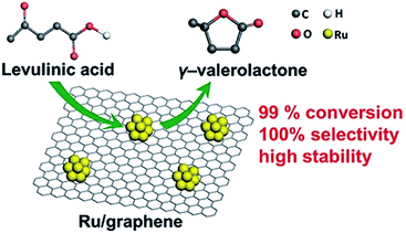 | ||
| Fig. 6 Ru/FLG catalyst in the conversion of LA to GVL. Reprinted with permission from ref. 77. Copyright (2016) American Chemical Society. | ||
The graphene-supported Ru catalysts were found to be two to four times more active than Ru NPs loaded on other traditional support materials. This effect was assigned to a higher fraction of Ru0 atoms on the NP surface, which was probably facilitated by the electron transfer from graphene. Also, the remarkable catalyst stability was assigned to enhanced adsorption of Ru NPs on FLG, which in turn, was mainly ascribed to the hybridization between the dsp states of the Ru NPs and the sp2 dangling bonds at the FLG defect sites.78
In the other example, RGO was impregnated with mixed copper oxide NPs (CuOx) at elevated temperatures and studied in the oxidation of biomass lignin derived isoeugenol to vanillin.79 Controlled experiments showed that CuOx and RGO separately are ineffective. The authors believe that the reaction proceeds via radical intermediates involving mixed valence Cu+ and Cu2+ species, while RGO plays the important role of allowing electron transfer. This work gives an interesting insight into the reaction mechanism with the above catalyst.
5.2. Formation of NPs in situ in the presence of CMG materials
The most common approach to synthesizing these nanocomposite catalysts is the formation of metal or metal compound NPs in the presence of CMG based materials. Mixed Cu0/Cu2O NPs were formed by simple impregnation of N-doped or undoped RGO as well as commercial graphite with Cu nitrate followed by thermal decomposition.80 It has been clearly demonstrated that RGO supports can control the size and morphology of Cu NPs, allowing for higher activity, selectivity and stability in the dehydrogenation of bioethanol to acetaldehyde. Bimetallic Pt/Ru NPs immobilized on RGO have been prepared from the Pt and Ru precursors H2PtCl6 × xH2O and RuCl3 × xH2O using impregnation and reduction at 300 °C.81 RGO was pre-fabricated from GO at a high temperature. This catalyst was tested in the electrooxidation of biomass-derived glycerol and showed higher activity than that of commercial 20 wt% Pt/C, demonstrating the influence of both the support and better catalyst dispersion obtained with RGO.The conversion of biomass-derived glycerol to lactic acid was successfully carried out in the presence of Cu2O NPs stabilized on GO.82 Here, Cu2O NPs (cubic, cCu2O, or rhombic dodecahedral, rCu2O, structures) were grown in the presence of GO, functioning as both the support and surfactant (Fig. 7). For these catalysts, superior shape-dependent catalytic activity and good stability have been demonstrated, revealing the advantages of GO as a stabilizer. In the case of simple mixtures of NPs and GO, no hybrid material was formed and no catalytic activity improvement was observed.
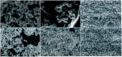 | ||
| Fig. 7 HRTEM of the synthesized materials. (a)–(c) rCu2O, rCu2O/GO, and hybrid rCu2O–GO. (d)–(f) cCu2O, cCu2O/GO, and hybrid cCu2O–GO, where rCu2O/GO and cCu2O/GO are admixtures of NPs and GO, while “hybrid” indicates NPs formed in situ on GO sheets. Reprinted with permission from ref. 82. Copyright (2014) Royal Society of Chemistry. | ||
A sonochemical method was used to form H4SiW12O40·nH2O (HSiW) NPs on the surface of graphene.83 This method allows a homogeneous distribution of comparatively large HSiW NPs on the graphene supports. Moreover, the sonication results in a special interaction between the graphene support and HSiW and also in the formation of hydrophobic cavities on the surface of graphene. These cavities allow the anchoring of glycogen (a water soluble polysaccharide derived from biomass) on the catalyst surface which leads to selective, fast, and efficient hydrolysis. This explains the high yield of glucose for this catalyst, which was about eight times higher than that obtained with the same amount of bare HSiW.
5.3. Simultaneous in situ formation of NPs and GO-to-RGO reduction
When GO is used in the catalyst preparation, it is often reduced to RGO in the same reaction procedure, making the catalyst preparation more facile and economical.The simultaneous formation of Pt NPs and RGO was carried out by microwave irradiation of GO and H2PtCl6 solution in ethylene glycol under exceptionally mild conditions.84 Microwave assisted reactions are known to be significantly accelerated.85,86 Here, it allows the NP formation and the GO-to-RGO transformation at 140 °C (instead of 900 °C (ref. 87)) within only a few minutes. The NP crystallization on RGO sheets along the (111) and (200) planes of Pt indicated that both sides of RGO sheets were accessible to Pt NPs and the NPs were well attached onto the RGO surface (Fig. 8). This prevented aggregation and facilitated intimate Pt–RGO contact. This design allows for an exceptionally active and selective catalyst for the production of 2,5-dimethylfuran via hydrogenation of HMF.
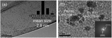 | ||
| Fig. 8 (a) TEM and (b) HRTEM images of Pt/RGO. Reprinted with permission from ref. 84. Copyright (2016) Elsevier. | ||
An active glucose electrooxidation catalyst has been formed by pyrolysis of a mixture of GO and a Cu phenanthroline complex at 900 °C in argon.87 This results in Cu0 NPs and Cu2+ ions stabilized on N-doped RGO. The authors discovered that the Cu2+ ions in this catalyst are bonded both with Cu0 NPs and N dopants of RGO as the active sites due to the development of different electron-donating effects toward Cu2+ ions. It was concluded that these ions are responsible for catalytic activity, although both copper NPs and RGO are necessary components of this catalyst.
A two-step strategy has been used for the preparation of a bifunctional catalyst consisting of Ru NPs supported on RGO and modified with benzenesulfonic acid groups (Fig. 9) for the hydrogenation of LA to GVL.88 The formation of Ru/RGO was accomplished via simultaneous reduction of RuCl3 × 3H2O and GO by hydrogen under hydrothermal conditions.
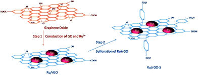 | ||
| Fig. 9 Schematic illustration of the catalyst preparation strategy. Reprinted with permission from ref. 88. Copyright (2017) American Chemical Society. | ||
The formation of a C–C bond between p-sulfophenyl and the sp2 carbon of graphene allowed for anchoring the acidic groups. The presence of acidic groups on RGO leads to a much higher GVL yield due to the accelerated dehydration process by strong acid sites. The authors envisioned that this method could be a general way to prepare graphene-based bifunctional catalysts, which are expected to have a broad range of applications in biomass conversion.
The outstanding catalytic properties in the conversion of biomass-derived polyols to chemicals were achieved due to a sophisticated design of the in situ synthesized catalyst based on CuPd NPs and RGO.89 Here, Cu and Pd salts as well as GO were simultaneously reduced with NaBH4. Crystal lattice engineering involving the Cu and RGO was employed to establish surface facet control over mono- and bimetallic Cu-based NPs (Fig. 10a). Because the Cu(111) surface plane has the lowest lattice parameter mismatch with graphene,90 it allows minimization of the lattice strain energy at the interface, resulting in the growth of the monometallic Cu or bimetallic CuPd NPs in the (111) direction on the RGO surface (Fig. 10b).
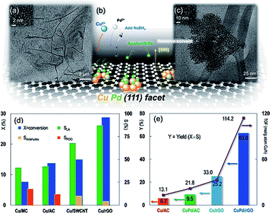 | ||
| Fig. 10 (a) TEM image of reduced graphene oxide (RGO). The inset HRTEM image shows the RGO lattice. (b) Brief illustration of the synthesis protocol: Cu2+ and Pd2+ were mixed with GO and then reduced to the metallic state in the aqueous phase with the protection of acetonitrile by hydrogen formed in situ by injecting NaBH4, resulting in a dominant CuPd(111) surface plane. The solvent was removed before catalytic activity tests. (c) TEM image of Cu(2 wt%)–Pd(0.05 wt%) bimetallic nanocrystals on the RGO support. The inset HRTEM image is of the Cu(2 wt%)–Pd(0.05 wt%)/RGO nanocatalyst. Experimental conditions in (d) and (e): glycerol, 100.0 kg m−3; solvent, H2O; Cu (and Pd) loading, 2 wt% (and 0.05 wt%); catalyst charge, 6.7 kg m−3; T = 473 K; PN2 = 1.4 MPa; NaOH/glycerol molar ratio, 1.1; LA, lactic acid; PDO, 1,2-propanediol; aldehydes, pyruvaldehyde and glyceraldehyde. For the vertical y-axis, X = conversion, S = selectivity, and Y = yield. Reaction time: 6 h in (d) and (e), except that the turnover frequency (TOF) in (e) is calculated at X ∼ 20% (reaction time = 0.5–6 h). Reprinted with permission from ref. 89. Copyright (2013) American Chemical Society. | ||
We believe that despite the seemingly simultaneous NaBH4 reduction, the RGO aromatic structure should be restored first to allow for the Cu directed growth. The novel and unsurpassed features of this work entail the directed growth of Cu nanocrystal facets using RGO as a 2D template and the co-crystallization with Pd to obtain outstanding activity and stability improvements. It is noteworthy that neither catalysts based on GO nor activated carbon allowed a comparable activity for either Cu or CuPd NPs. This work manifests a real paradigm shift in how graphene based materials can be intelligently designed. On the other hand, there are examples where GO is used as the support for stabilizing metal NPs (e.g. Pt91 and AuPd92), and the catalytic performance of such catalysts in biomass conversion to chemicals is inferior as compared to that of the catalysts based on carbon nanotubes (CNT). Thus, if the advantages of the support material in controlling the catalyst structure are not realized, no catalytic benefits are obtained.
5.4. A bottom-up, fully in situ approach to synthesize both NPs and CMGs from small molecules
It is well established that 2,5-dimethylfuran (DMFU) can be used in liquid fuels and can be produced from biomass derived HMF. In ref. 93 the authors developed a CuCo bimetallic NP catalyst supported on N-graphene-modified Al2O3 (CuCo®/NGr/α-Al2O3) through the impregnation of alumina with an ethanol solution of Co and Cu acetates with 1,10-phenanthroline (carbon source), followed by calcination and reduction. This results in the dispersion of CuCo NPs in the alumina infused with N-doped graphene (Fig. 11).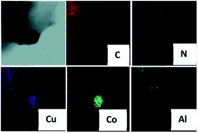 | ||
| Fig. 11 EDS maps of CuCo®/NGr/α-Al2O3. Reprinted with permission from ref. 93. Copyright (2016) Royal Society of Chemistry. | ||
The authors demonstrated that this catalyst could effectively catalyse the transformation of HMF into DMFU, yielding 99% of the target product. The authors believe that the high yield is due to the inability of this catalyst to catalyse the hydrogenation of the C![[double bond, length as m-dash]](https://www.rsc.org/images/entities/char_e001.gif) C bond in the furan ring, while being very active in C–O bond cleavage and C
C bond in the furan ring, while being very active in C–O bond cleavage and C![[double bond, length as m-dash]](https://www.rsc.org/images/entities/char_e001.gif) O bond hydrogenation. The interaction of bimetallic CuCo NPs with the nitrogen of N-doped graphene creates a synergistic effect, making it the first example of an active, non-noble metal catalyst for this reaction.
O bond hydrogenation. The interaction of bimetallic CuCo NPs with the nitrogen of N-doped graphene creates a synergistic effect, making it the first example of an active, non-noble metal catalyst for this reaction.
Another example of a fully in situ, one-step synthesis was recently demonstrated by Hou and coworkers.94 They synthesized Ru-containing catalysts for upgrading bio-oil by hydrogenation via a strategy involving controlled pyrolysis of a mixture of RuCl3, glucose and melamine at 700 °C. This resulted in Ru NPs being attached to the surface of carbon sheets (CS) and encapsulated by an ultrathin N-doped graphene (G) layer (only 1–2 layers) (Fig. 12).
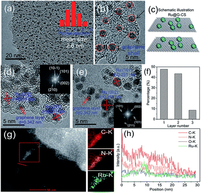 | ||
| Fig. 12 HRTEM images (a–e), schematic illustration of the structure (c), the number of graphene layers over Ru NPs (f), HAADF-STEM image and EDX mapping (g), and EDS line scan elemental analysis (h) of Ru@G-CS-700. Reprinted with permission from ref. 94. Copyright (2016) Royal Society of Chemistry. | ||
Ru@G-CS-700 demonstrated an exceptional performance in the hydrogenation of phenols and aromatics in bio-oil under mild conditions, while the hydrogenation of furfurals was more difficult. Unfortunately, the authors did not discuss how this unique catalyst structure influences the catalytic properties, apparently leaving it to further studies.
Han and co-workers proposed an excellent in situ method to prepare a Ru/graphene catalyst using glucose as the carbon source.95 The simplicity of the method, in which a solution of glucose, RuCl3 and FeCl3 in water was evaporated and then calcined at 700 °C, and the high quality of graphene formed make it especially appealing. In this process, the FeCl3 acts as both the sacrificial template and catalyst for the graphene formation.96 The Ru (2–6 nm NPs)/graphene catalyst showed much higher activity in the hydrogenation of LA to GVL compared to commercial Ru/C and was active even at room temperature. The authors explained the high activity by the unique electronic structure of graphene, which results in an electron-enriched Ru nanocatalyst.
6. Magnetically recoverable catalysts
In the last decade magnetically recoverable (MR) catalysts have received considerable attention due to more environmentally friendly processes, conservation of energy, and cheaper target products.97–105 Such catalysts are widely used for biomass and bio-oil related processes.106–115 MR graphene based catalysts are also well developed and utilized in many catalytic reactions.116–121 At the same time, to the best of our knowledge, there are only a few recent examples, where MR graphene based catalysts have been used for biomass and bio-oil relevant catalytic reactions. One such example reports a magnetic solid acid, Fe3O4–RGO–SO3H, which was employed to obtain HMF directly from fructose followed by the utilization of another MR catalyst, ZnFe1.65Ru0.35O4, to obtain 2,5-diformylfuran (DFF) and 2,5-furandicarboxylic acid (FDCA) (Fig. 13).122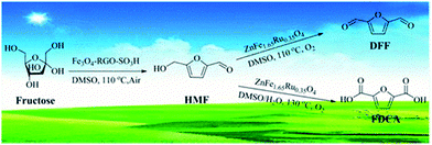 | ||
| Fig. 13 Schematic representation of the transformation of fructose into HMF with magnetic RGO based catalysts and then to DFF and FDCA with ZnFe1.65Ru0.35O4. Reprinted with permission from ref. 122. Copyright (2017) American Chemical Society. | ||
A catalyst based on MR graphene, bearing –SO3H, –COOH and –OH functional groups, along with iron NPs has been reported for the hydrolysis of cellulose to saccharides (Fig. 14).123 This catalyst allowed for high yields (up to 98%) of monosaccharides and disaccharides at lower reaction temperatures (75 °C) than normally used in this process (125 °C).
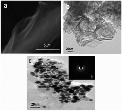 | ||
| Fig. 14 SEM (a) and TEM (b) images of functionalized graphene, G-SO3H; (c) image of Fe-G-SO3H (the inset shows the electron diffraction pattern). The catalyst used is magnetically recoverable. Reprinted with permission from ref. 123. Copyright (2013) Royal Society of Chemistry. | ||
A sophisticated catalyst has been developed combining Fe3O4 NPs, N-doped RGO, and bimetallic Pd based NPs through a simple one-pot reaction under mild conditions.124 To accomplish this, GO was mixed in water with Fe(II) and Fe(III) salts as well as Pd and Ag (Co, Au, and Pt) salts. Reduction with hydrazine monohydrate at 90 °C resulted in N-doped RGO, Fe3O4 NPs, and bimetallic PdAg (PdCo, PtAu, and PdPt) NPs (Fig. 15). This is a novel strategy for the preparation of multicomponent and multifunctional transition-metal catalysts. The catalyst developed was employed for the selective upgrading of biomass-derived vanillin, isatin, and two types of benzyl phenyl ethers (lignin biomass-derived model compounds) as well as synthetic feedstocks derived from aromatic compounds. This novel catalyst was effective in the dehydrogenation of formic acid to form H2 and subsequent utilization of the hydrogen generated in situ for upgrading bio-oil and chemical feedstocks. Moreover, the authors discovered that Fe3O4 does not simply facilitate the catalyst separation with a magnetic field; it also improves the TOF of the reaction presumably by facilitating the catalytic cycle of the tandem reactions.
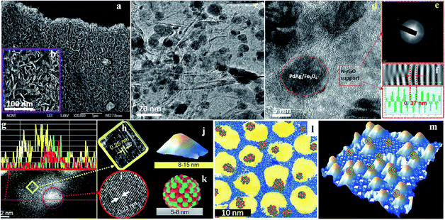 | ||
| Fig. 15 Microscopy analysis and proposed structure of the Pd50Ag50/Fe3O4/N-RGO catalyst: (a and b) SEM images; (c) low-resolution TEM image; (d) high-resolution TEM image; (e) selected area electron diffraction pattern of the N-RGO layer; (f) d-spacing from stacked N-RGO layers; (g) dark field HAADF images with elemental line profile (yellow line, Fe; green line, Pd; red line, Ag); (h and i) CS-corrected TEM images of magnetite and PdAg nanoalloy; (j and k) proposed models for Fe3O4 and PdAg nanoalloy; (l) 2D scratch art model (yellow, magnetite; blue background, N-RGO; and green/red cluster, PdAg alloy); and (m) proposed 3D structural model. Reprinted with permission from ref. 124. Copyright (2015) American Chemical Society. | ||
7. Concluding remarks
Here, we return to the original question raised in the Introduction: what does the future hold? In other words, what are the most promising avenues for catalyst development for biomass conversion? Numerous reviews including ours have demonstrated that the presence of aromaticity in RGO is an important factor for π–π interactions and for controlling the NP growth along the crystalline graphene sheets. However, if RGO functionalities are limited, poor solubility of such supports can impede further catalyst development. Thus, if RGO is obtained from GO, one should take this aspect into account when choosing the reduction/functionalization conditions. In the case of CMG formation from biomass, again both the graphene quality and solubility are the key factors for successful utilization. These could be controlled by varying the temperature, time, addition of a catalyst, etc.Another obvious conclusion from the surveyed literature is that a fully in situ catalyst synthesis from small molecules (especially, biomass derived as a carbon source) through a one-pot procedure is the most advantageous from the viewpoint of simplicity and low cost; however, one needs to bear in mind the mechanistic aspects of such a catalyst formation. The formation of graphene moieties needs to either precede or coincide with the formation of metal/metal compound NPs in order to realize the advantages of co-crystallization, well-defined structures and intimate contact between the catalyst components to allow a synergistic effect in catalysis.
Finally, we believe that magnetically recoverable graphene based catalysts are underutilized in biomass conversion. Our recent work demonstrated that even in the case of solid cellulose and heterogeneous MR hydrophilic catalysts, 100% cellulose conversion can be achieved,113 making MR catalysts coupled with CMG components especially appealing. Considering that no data have been reported to suggest that the presence of magnetic NPs in graphene, GO, or RGO based catalysts has a detrimental effect on catalysis, we believe that there is a great niche where catalytic and magnetic NPs can be combined on graphene based supports (instead of traditional porous supports) and used for biomass valorisation reactions.
Conflicts of interest
There are no conflicts to declare.Acknowledgements
V. K. D. acknowledges the SERB Indo-US Postdoctoral Fellowship 2016/43 for funding. Z. B. S. thanks the Russian Science Foundation for financial support (#15-13-30026).Notes and references
- S. Zhu, J. Wang and W. Fan, Catal. Sci. Technol., 2015, 5, 3845–3858 CAS.
- S. Mondal, J. Mondal and A. Bhaumik, ChemCatChem, 2015, 7, 3570–3578 CrossRef CAS.
- S. K. Bardhan, S. Gupta, M. E. Gorman and M. A. Haider, Renewable Sustainable Energy Rev., 2015, 51, 506–520 CrossRef CAS.
- H.-K. Lai, Y.-Z. Chou, M.-H. Lee and K.-Y. A. Lin, Chem. Eng. J., 2018, 332, 717–726 CrossRef CAS.
- C. Li, G. Xu, X. Liu, Y. Zhang and Y. Fu, Ind. Eng. Chem. Res., 2017, 56, 8843–8849 CrossRef CAS.
- M. A. Sanhoob, O. Muraza, E. N. Shafei, T. Yokoi and K.-H. Choi, Appl. Catal., B, 2017, 210, 432–443 CrossRef CAS.
- T. P. Sulmonetti, B. Hu, S. Lee, P. K. Agrawal and C. W. Jones, ACS Sustainable Chem. Eng., 2017, 5, 8959–8969 CrossRef CAS.
- H. Zhong, Q. Li, J. Liu, G. Yao, J. Wang, X. Zeng, Z. Huo and F. Jin, ACS Sustainable Chem. Eng., 2017, 5, 6517–6523 CrossRef CAS.
- S. S. Dalli, T. J. Tilaye and S. K. Rakshit, Ind. Eng. Chem. Res., 2017, 56, 10582–10590 CrossRef CAS.
- I.-Y. Jeon, H.-J. Choi, S.-M. Jung, J.-M. Seo, M.-J. Kim, L. Dai and J.-B. Baek, J. Am. Chem. Soc., 2013, 135, 1386–1393 CrossRef CAS PubMed.
- K. S. Novoselov, A. K. Geim, S. V. Morozov, D. Jiang, Y. Zhang, S. V. Dubonos, I. V. Grigorieva and A. A. Firsov, Science, 2004, 306, 666–669 CrossRef CAS PubMed.
- A. Celis, M. N. Nair, A. Taleb-Ibrahimi, E. H. Conrad, C. Berger, W. A. de Heer and A. Tejeda, J. Phys. D: Appl. Phys., 2016, 49, 143001 CrossRef.
- D. W. Chang and J.-B. Baek, J. Mater. Chem. A, 2016, 4, 15281–15293 CAS.
- S. S. Shams, R. Zhang and J. Zhu, Mater. Sci.-Pol., 2015, 33, 566–578 CAS.
- L. Chen, Y. Hernandez, X. Feng and K. Muellen, Angew. Chem., Int. Ed., 2012, 51, 7640–7654 CrossRef CAS PubMed.
- M. G. Schwab, A. Narita, Y. Hernandez, T. Balandina, K. S. Mali, S. De Feyter, X. Feng and K. Muellen, J. Am. Chem. Soc., 2012, 134, 18169–18172 CrossRef CAS PubMed.
- Z. Chen, W. Zhang, C.-A. Palma, A. Lodi Rizzini, B. Liu, A. Abbas, N. Richter, L. Martini, X.-Y. Wang, N. Cavani, H. Lu, N. Mishra, C. Coletti, R. Berger, F. Klappenberger, M. Klaeui, A. Candini, M. Affronte, C. Zhou, V. De Renzi, U. del Pennino, J. V. Barth, H. J. Raeder, A. Narita, X. Feng and K. Muellen, J. Am. Chem. Soc., 2016, 138, 15488–15496 CrossRef CAS PubMed.
- Q. Li, S. Zhang, L. Dai and L.-s. Li, J. Am. Chem. Soc., 2012, 134, 18932–18935 CrossRef CAS PubMed.
- X.-H. Li, S. Kurasch, U. Kaiser and M. Antonietti, Angew. Chem., Int. Ed., 2012, 51, 9689–9692 CrossRef CAS PubMed.
- A. Bayat and E. Saievar-Iranizad, J. Lumin., 2017, 192, 180–183 CrossRef CAS.
- S. Mittal, V. Kumar, N. Dhiman, L. K. S. Chauhan, R. Pasricha and A. K. Pandey, Sci. Rep., 2016, 6, 39548 CrossRef CAS PubMed.
- S.-M. Tsai, P. Bangalore, E. Y. Chen, D. Lu, M.-H. Chiu, A. Suh, M. Gehring, J. P. Cangco, S. G. Garcia and W.-C. Chin, J. Nanopart. Res., 2017, 19, 1–13 CrossRef CAS.
- M. Ema, M. Gamo and K. Honda, Regul. Toxicol. Pharmacol., 2017, 85, 7–24 CrossRef CAS PubMed.
- J. Russier, V. Leon, M. Orecchioni, E. Hirata, P. Virdis, C. Fozza, F. Sgarrella, G. Cuniberti, M. Prato, E. Vazquez, A. Bianco and L. G. Delogu, Angew. Chem., Int. Ed., 2017, 56, 3014–3019 CrossRef CAS PubMed.
- E. Lam and J. H. T. Luong, ACS Catal., 2014, 4, 3393–3410 CrossRef CAS.
- C. Chang, Z. Song, J. Lin and Z. Xu, RSC Adv., 2013, 3, 2720–2726 RSC.
- W. Gao, L. B. Alemany, L. Ci and P. M. Ajayan, Nat. Chem., 2009, 1, 403–408 CrossRef CAS PubMed.
- S. F. Kiew, L. V. Kiew, H. B. Lee, T. Imae and L. Y. Chung, J. Controlled Release, 2016, 226, 217–228 CrossRef CAS PubMed.
- A. D. Zdetsis and E. N. Economou, Adv. Mater. Lett., 2017, 8, 2–7 Search PubMed.
- L. E. Foa Torres, S. Roche and J. C. Charlier, Introduction to Graphene-based Nanomaterials, Cambridge University Press Cambridge, UK, 2014 Search PubMed.
- S. Thakur and N. Karak, Carbon, 2015, 94, 224–242 CrossRef CAS.
- E. D. Grayfer, V. G. Makotchenko, A. S. Nazarov, S. J. Kim and V. E. Fedorov, Russ. Chem. Rev., 2011, 80, 751–770 CrossRef CAS.
- S. Bai and X. Shen, RSC Adv., 2012, 2, 64–98 RSC.
- X. Huang, X. Qi, F. Boey and H. Zhang, Chem. Soc. Rev., 2012, 41, 666–686 RSC.
- N. Zhang, Y. Zhang and Y. J. Xu, Nanoscale, 2012, 4, 5792–5813 RSC.
- D. R. Kauffman and A. Star, Analyst, 2010, 135, 2790–2797 RSC.
- P. Wu, W. Zhu, B. Dai, Y. Chao, C. Li, H. Li, M. Zhang, W. Jiang and H. Li, Chem. Eng. J., 2016, 301, 123–131 CrossRef CAS.
- K. S. Novoselov, A. K. Geim, S. V. Morozov, D. Jiang, Y. Zhang, S. V. Dubonos, I. V. Grigorieva and A. A. Firsov, Science, 2004, 306, 666–669 CrossRef CAS PubMed.
- D. R. Dreyer, S. Park, C. W. Bielawski and R. S. Ruoff, Chem. Soc. Rev., 2010, 39, 228–240 RSC.
- F. M. Koehler and W. J. Stark, Acc. Chem. Res., 2012, 46, 2297–2306 CrossRef PubMed.
- S. Stankovich, D. A. Dikin, R. D. Piner, K. A. Kohlhaas, A. Kleinhammes, Y. Jia, Y. Wu, S. T. Nguyen and R. S. Ruoff, Carbon, 2007, 45, 1558–1565 CrossRef CAS.
- J. Zhang, H. Yang, G. Shen, P. Cheng, J. Zhang and S. Guo, Chem. Commun., 2010, 46, 1112–1114 RSC.
- Q. Li, W. Zhu, J. Fu, H. Zhang, G. Wu and S. Sun, Nano Energy, 2016, 24, 1–9 CrossRef CAS.
- W.-W. Wang, J.-S. Dang, X. Zhao and S. Nagase, J. Phys. Chem. C, 2016, 120, 5673–5681 CAS.
- D. Kepic, S. Sandoval, A. Perez del Pino, E. Gyoergy, L. Cabana, B. Ballesteros and G. Tobias, ChemPhysChem, 2017, 18, 935–941 CrossRef CAS PubMed.
- W. S. Hummers Jr and R. E. Offeman, J. Am. Chem. Soc., 1958, 80, 1339 CrossRef.
- D. C. Marcano, D. V. Kosynkin, J. M. Berlin, A. Sinitskii, Z. Sun, A. Slesarev, L. B. Alemany, W. Lu and J. M. Tour, ACS Nano, 2010, 4, 4806–4814 CrossRef CAS PubMed.
- H. Yu, B. Zhang, C. Bulin, R. Li and R. Xing, Sci. Rep., 2016, 6, 36143 CrossRef CAS PubMed.
- E. Lam and J. H. Luong, ACS Catal., 2014, 4, 3393–3410 CrossRef CAS.
- S. S. Shams, L. S. Zhang, R. Hu, R. Zhang and J. Zhu, Mater. Lett., 2015, 161, 476–479 CrossRef CAS.
- G. Ruan, Z. Sun, Z. Peng and J. M. Tour, ACS Nano, 2011, 5, 7601–7607 CrossRef CAS PubMed.
- H. Zhou, J. Zhang, J. Zhu, Z. Liu, C. Zhang and S. Mu, RSC Adv., 2016, 6, 73292–73300 RSC.
- C. Guo, W. Liao, Z. Li, L. Sun, H. Ruan, Q. Wu, Q. Luo, J. Huang and C. Chen, Sci. Bull., 2016, 61, 948–958 CrossRef CAS.
- D. Ye, L. Wang, R. Zhang, B. Liu, Y. Wang and J. Kong, J. Mater. Chem. A, 2015, 3, 15171–15176 CAS.
- S. Gao, H. Liu, K. Geng and X. Wei, Nano Energy, 2015, 12, 785–793 CrossRef CAS.
- B. Men, Y. Sun, M. Li, C. Hu, M. Zhang, L. Wang, Y. Tang, Y. Chen, P. Wan and J. Pan, ACS Appl. Mater. Interfaces, 2016, 8, 1415–1423 CAS.
- S. Y. Oh, J. G. Son and P. C. Chiu, Environ. Toxicol. Chem., 2013, 32, 501–508 CrossRef CAS PubMed.
- S. Liu, S. Zhao, Y. Yao, P. Dong and C. Yang, J. Mater. Sci. Technol., 2014, 30, 466–472 CAS.
- D. Mondal, M. Sharma, C. H. Wang, Y. C. Lin, H. C. Huang, A. Saha, S. K. Nataraj and K. Prasad, Green Chem., 2016, 18, 2819–2826 RSC.
- X. Zeng, L. Leng, F. Liu, G. Wang, Y. Dong, L. Du, L. Liu and S. Liao, Electrochim. Acta, 2016, 200, 231–238 CrossRef CAS.
- X. Xu, J. Zhou, D. H. Nagaraju, L. Jiang, V. R. Marinov, G. Lubineau, H. N. Alshareef and M. Oh, Adv. Funct. Mater., 2015, 25, 3193–3202 CrossRef CAS.
- A. Elmouwahidi, J. F. Vivo-Vilches, A. F. Pérez-Cadenas, F. J. Maldonado-Hódar and F. Carrasco-Marín, Chem. Eng. J., 2016, 306, 1109–1115 CrossRef CAS.
- L. Sun, C. Tian, M. Li, X. Meng, L. Wang, R. Wang, J. Yin and H. Fu, J. Mater. Chem. A, 2013, 1, 6462–6470 CAS.
- P. Lu, Q. Huang, Y. Chi and J. Yan, J. Anal. Appl. Pyrolysis, 2017, 127, 47–56 CrossRef CAS.
- D. H. Seo, S. Pineda, J. Fang, Y. Gozukara, S. Yick, A. Bendavid, S. K. H. Lam, A. T. Murdock, A. B. Murphy, Z. J. Han and K. K. Ostrikov, Nat. Commun., 2017, 8, 1–9 CrossRef PubMed.
- C. Lavorato, A. Primo, R. Molinari and H. Garcia, Chem.–Eur. J., 2014, 20, 187–194 CrossRef CAS PubMed.
- A. V. Nakhate and G. D. Yadav, ACS Sustainable Chem. Eng., 2016, 4, 1963–1973 CrossRef CAS.
- D. Krishnan, K. Raidongia, J. Shao and J. Huang, ACS Nano, 2014, 8, 449–457 CrossRef CAS PubMed.
- D. Mondal, J. P. Chaudhary, M. Sharma and K. Prasad, RSC Adv., 2014, 4, 29834–29839 RSC.
- H. Ma, C. Li, M. Zhang, J.-D. Hong and G. Shi, J. Mater. Chem. A, 2017, 5, 17040–17047 CAS.
- H. Wang, Y. Wang, T. Deng, C. Chen, Y. Zhu and X. Hou, Catal. Commun., 2015, 59, 127–130 CrossRef CAS.
- A. V. Nakhate and G. D. Yadav, ACS Sustainable Chem. Eng., 2016, 4, 1963–1973 CrossRef CAS.
- H. Wang, Q. Kong, Y. Wang, T. Deng, C. Chen, X. Hou and Y. Zhu, ChemCatChem, 2014, 6, 728–732 CrossRef CAS.
- A. D. Sutton, F. D. Waldie, R. Wu, M. Schlaf, L. A. Pete' Silks III and J. C. Gordon, Nat. Chem., 2013, 5, 428–432 CrossRef CAS PubMed.
- S. Dutta, A. Bohre, W. Zheng, G. R. Jenness, M. Nunez, B. Saha and D. G. Vlachos, ACS Catal., 2017, 7, 3905–3915 CrossRef CAS.
- S. Zhu, C. Chen, Y. Xue, J. Wu, J. Wang and W. Fan, ChemCatChem, 2014, 6, 3080–3083 CrossRef CAS.
- C. Xiao, T.-W. Goh, Z. Qi, S. Goes, K. Brashler, C. Perez and W. Huang, ACS Catal., 2016, 6, 593–599 CrossRef CAS.
- X. Liu, K. X. Yao, C. Meng and Y. Han, Dalton Trans., 2012, 41, 1289–1296 RSC.
- A. Bohre, D. Gupta, M. I. Alam, R. K. Sharma and B. Saha, ChemistrySelect, 2017, 2, 3129–3136 CrossRef CAS.
- M. V. Morales, E. Asedegbega-Nieto, B. Bachiller-Baeza and A. Guerrero-Ruiz, Carbon, 2016, 102, 426–436 CrossRef CAS.
- H. J. Kim, S. M. Choi, M. H. Seo, S. Green, G. W. Huber and W. B. Kim, Electrochem. Commun., 2011, 13, 890–893 CrossRef CAS.
- C. Hong, X. Jin, J. Totleben, J. Lohrman, E. Harak, B. Subramaniam, R. V. Chaudhari and S. Ren, J. Mater. Chem. A, 2014, 2, 7147–7151 CAS.
- M. Klein, A. Varvak, E. Segal, B. Markovsky, I. N. Pulidindi, N. Perkas and A. Gedanken, Green Chem., 2015, 17, 2418–2425 RSC.
- J. Shi, Y. Wang, X. Yu, W. Du and Z. Hou, Fuel, 2016, 163, 74–79 CrossRef CAS.
- S. Nekkanti, K. Veeramani, N. Praveen Kumar and N. Shankaraiah, Green Chem., 2016, 18, 3439–3447 RSC.
- J. Zhou, W. Xu, Z. You, Z. Wang, Y. Luo, L. Gao, C. Yin, R. Peng and L. Lan, Sci. Rep., 2016, 6, 25149 CrossRef CAS PubMed.
- J. Wang, T.-T. Wang, F.-B. Wang, D.-Y. Zhang, K. Wang and X.-H. Xia, J. Phys. Chem. C, 2016, 120, 15593–15599 CAS.
- Y. Wang, Z. Rong, Y. Wang, T. Wang, Q. Du, Y. Wang and J. Qu, ACS Sustainable Chem. Eng., 2017, 5, 1538–1548 CrossRef CAS.
- X. Jin, L. Dang, J. Lohrman, B. Subramaniam, S. Ren and R. V. Chaudhari, ACS Nano, 2013, 7, 1309–1316 CrossRef CAS PubMed.
- X. Li, W. Cai, J. An, S. Kim, J. Nah, D. Yang, R. Piner, A. Velamakanni, I. Jung, E. Tutuc, S. K. Banerjee, L. Colombo and R. S. Ruoff, Science, 2009, 324, 1312–1314 CrossRef CAS PubMed.
- B. Kaya, S. Irmak, A. Hasanoglu and O. Erbatur, Int. J. Hydrogen Energy, 2014, 39, 10135–10140 CrossRef CAS.
- X. Wan, C. Zhou, J. Chen, W. Deng, Q. Zhang, Y. Yang and Y. Wang, ACS Catal., 2014, 4, 2175–2185 CrossRef CAS.
- W. Guo, H. Liu, S. Zhang, H. Han, H. Liu, T. Jiang, B. Han and T. Wu, Green Chem., 2016, 18, 6222–6228 RSC.
- J. Shi, M. Zhao, Y. Wang, J. Fu, X. Lu and Z. Hou, J. Mater. Chem. A, 2016, 4, 5842–5848 CAS.
- L. Wu, J. Song, B. Zhou, T. Wu, T. Jiang and B. Han, Chem.–Asian J., 2016, 11, 2792–2796 CrossRef CAS PubMed.
- B. Zhang, J. Song, G. Yang and B. Han, Chem. Sci., 2014, 5, 4656–4660 RSC.
- Y. Zhu, S. C. Peng, A. Emi, Z. Su, V. Monalisa and R. A. Kemp, Adv. Synth. Catal., 2007, 349, 1917–1922 CrossRef CAS.
- V. Polshettiwar, R. Luque, A. Fihri, H. Zhu, M. Bouhrara and J.-M. Basset, Chem. Rev., 2011, 111, 3036–3075 CrossRef CAS PubMed.
- L. M. Rossi, F. P. Silva, L. L. R. Vono, P. K. Kiyohara, E. L. Duarte, R. Itri, R. Landers and G. Machado, Green Chem., 2007, 9, 379–385 RSC.
- A. Saha, J. Leazer and R. S. Varma, Green Chem., 2012, 14, 67–71 RSC.
- B. R. Vaddula, A. Saha, J. Leazer and R. S. Varma, Green Chem., 2012, 14, 2133–2136 RSC.
- D. Wang and D. Astruc, Chem. Rev., 2014, 114, 6949–6985 CrossRef CAS PubMed.
- A.-H. Lu, E. L. Salabas and F. Schueth, Angew. Chem., Int. Ed., 2007, 46, 1222–1244 CrossRef CAS PubMed.
- A. Bazgir, G. Hosseini and R. Ghahremanzadeh, ACS Comb. Sci., 2013, 15, 530–534 CrossRef CAS PubMed.
- D. Kundu, T. Chatterjee and B. C. Ranu, Adv. Synth. Catal., 2013, 355, 2285–2296 CrossRef CAS.
- B. Liu and Z. Zhang, ACS Catal., 2016, 6, 326–338 CrossRef CAS.
- V. V. Costa, M. J. Jacinto, L. M. Rossi, R. Landers and E. V. Gusevskaya, J. Catal., 2011, 282, 209–214 CrossRef CAS.
- K. Alibegovic, D. G. Morgan, Y. Losovyj, M. Pink, B. D. Stein, N. V. Kuchkina, E. S. Serkova, K. E. Salnikova, Z. B. Shifrina, V. G. Matveeva, E. M. Sulman and L. M. Bronstein, ChemistrySelect, 2017, 2, 5485–5491 CrossRef CAS.
- A. M. Hengne, A. V. Malawadkar, N. S. Biradar and C. V. Rode, RSC Adv., 2014, 4, 9730–9736 RSC.
- E. Y. C. Jorge, T. d. M. Lima, C. G. S. Lima, L. Marchini, W. N. Castelblanco, D. G. Rivera, E. A. Urquieta-Gonzalez, R. S. Varma and M. W. Paixao, Green Chem., 2017, 19, 3856–3868 RSC.
- V. Kuncser, S. M. Coman, E. Kemnitz and V. I. Parvulescu, J. Appl. Phys., 2015, 117, 17D724 CrossRef.
- H. Li, Z. Fang and S. Yang, ChemPlusChem, 2016, 81, 135–142 CrossRef CAS.
- O. V. Manaenkov, J. J. Mann, O. V. Kislitza, Y. Losovyj, B. D. Stein, D. G. Morgan, M. Pink, O. L. Lependina, Z. B. Shifrina, V. G. Matveeva, E. M. Sulman and L. M. Bronstein, ACS Appl. Mater. Interfaces, 2016, 8, 21285–21293 CAS.
- S. Wang, Z. Zhang, B. Liu and J. Li, Ind. Eng. Chem. Res., 2014, 53, 5820–5827 CrossRef CAS.
- Y. Xiong, Z. Zhang, X. Wang, B. Liu and J. Lin, Chem. Eng. J., 2014, 235, 349–355 CrossRef CAS.
- A. Schaetz, M. Zeltner and W. J. Stark, ACS Catal., 2012, 2, 1267–1284 CrossRef CAS.
- J. Tucek, K. C. Kemp, K. S. Kim and R. Zboril, ACS Nano, 2014, 8, 7571–7612 CrossRef CAS PubMed.
- M. Gholinejad, J. Ahmadi, C. Najera, M. Seyedhamzeh, F. Zareh and M. Kompany-Zareh, ChemCatChem, 2017, 9, 1442–1449 CrossRef CAS.
- M. Karthik and P. Suresh, ChemistrySelect, 2017, 2, 6916–6928 CrossRef CAS.
- B. Wang, L. Si, J. Geng, Y. Su, Y. Li, X. Yan and L. Chen, Appl. Catal., B, 2017, 204, 316–323 CrossRef CAS.
- J. Zhang, T. Yao, C. Guan, N. Zhang, H. Zhang, X. Zhang and J. Wu, J. Colloid Interface Sci., 2017, 505, 130–138 CrossRef CAS PubMed.
- Z. Yang, W. Qi, R. Su and Z. He, Energy Fuels, 2017, 31, 533–541 CrossRef CAS.
- D. Verma, R. Tiwari and A. K. Sinha, RSC Adv., 2013, 3, 13265–13272 RSC.
- A. K. Singh, S. Jang, J. Y. Kim, S. Sharma, K. C. Basavaraju, M.-G. Kim, K.-R. Kim, J. S. Lee, H. H. Lee and D.-P. Kim, ACS Catal., 2015, 5, 6964–6972 CrossRef CAS.
| This journal is © The Royal Society of Chemistry 2017 |


