
 Open Access Article
 This Open Access Article is licensed under a Creative Commons Attribution-Non Commercial 3.0 Unported Licence
Azetidinium lead iodide for perovskite solar cells†
S. R.
Pering
a,
W.
Deng
a,
J. R.
Troughton
c,
P. S.
Kubiak
ab,
D.
Ghosh
e,
R. G.
Niemann
a,
F.
Brivio
a,
F. E.
Jeffrey
d,
A. B.
Walker
e,
M. S.
Islam
 ad,
T. M.
Watson
c,
P. R.
Raithby
a,
A. L.
Johnson
ad,
S. E.
Lewis
ad and
P. J.
Cameron
*ad
ad,
T. M.
Watson
c,
P. R.
Raithby
a,
A. L.
Johnson
ad,
S. E.
Lewis
ad and
P. J.
Cameron
*ad
aDepartment of Chemistry, University of Bath, Claverton Down, Bath, BA2 7AY, UK. E-mail: p.j.cameron@bath.ac.uk
bCentre for Doctoral Training in New and Sustainable Photovoltaics, University of Liverpool, UK
cSPECIFIC, Swansea University College of Engineering, Bay Campus, Swansea, SA1 8EN, UK
dCentre for Sustainable Chemical Technologies, University of Bath, Claverton Down, Bath, BA2 7AY, UK
eDepartment of Physics, University of Bath, Claverton Down, Bath, BA2 7AY, UK
First published on 20th September 2017
Abstract
Hybrid organic–inorganic perovskites have been established as good candidate materials for emerging photovoltaics, with device efficiencies of over 22% being reported. There are currently only two organic cations, methylammonium and formamidinium, which produce 3D perovskites with band gaps suitable for photovoltaic devices. Numerous computational studies have identified azetidinium as a potential third cation for synthesizing organic–inorganic perovskites, but to date no experimental reports of azetidinium containing perovskites have been published. Here we prepare azetidinium lead iodide for the first time. Azetidinium lead iodide is a stable, bright orange material which does not appear to form a 3D or a 2D perovskite. It was successfully used as the absorber layer in solar cells. We also show that it is possible to make mixed cation devices by adding the azetidinium cation to methylammonium lead iodide. Computational studies show that the substitution of up to 5% azetidinium into the methylammonium lead iodide is energetically favourable and that phase separation does not occur at these concentrations. Mixed azetidinium–methylammonium cells show improved performance and reduced hysteresis compared to methylammonium lead iodide cells.
Introduction
The amount of research into organo lead halide perovskites for Perovskite Solar Cells (PSC) has increased rapidly since 2012.1–3 The benefits of PSC include fabrication using facile solution processing methods,2,4 and the ability to easily tune properties like band gap and colour.5,6 Methylammonium lead iodide (MAPI) solar cells have reached efficiencies of over 15%.7 MAPI has a bandgap of 1.6 eV,8 which is higher than the optimum band gap for solar cells of 1.1–1.4 eV.9,10 Band gap engineering is possible by mixing halide ions to form MAPbI3−yXy, where X is either chloride or bromide.6,8 Alternatively the lead cation can be exchanged for tin. MASnI3 has a lower bandgap of 1.3 V, and MASnI3 PSC can reach efficiencies of 5.7%.11 However MASnI3 has been shown to be more unstable and more toxic than MAPI.12,13To date, variation of the organic cation has received much less attention compared to variation of the halide and group 14 metal components of the perovskite. This is likely due to the perceived lack of alternatives to methylammonium. Formamidinium (FA) is the only alternative organic cation that has been shown to produce a 3D perovskite. FAPbI3 has a band gap of 1.48 eV, and solar cells have been prepared with efficiencies of up to 16%.14,15 An alternative approach is to replace the organic cation with an inorganic caesium cation. CsPbI3 cells have reached 2.9% efficiency;16 Cs+ has also been used as an additive in MAPI cells, improving both the efficiency and stability.16,17 Mixed cation perovskites, e.g. containing formamidinium and methylammonium show efficiencies of over 18%, and a band gap more closely aligned to that of its contact layers.18 Tri-cation perovskites with the formula Cs5(MA0.17FA0.83)95Pb(I0.83Br0.17)3 have shown high efficiencies of 22.1% and improved stability relative to single cation perovskites.19,20 Methylammonium and formamidinium are by far the most common cations that are used in high efficiency 3D perovskite solar cells. Organo-lead halide perovskites have been produced using n-butylammonium cations, but the larger size of the cation means that a 2D rather than a 3D perovskite is created.21 Guanidinium lead iodide also forms a 2D perovskite, but the addition of small amounts of guanidinium to MAPI can improve the open-circuit voltage in the resulting devices.22 2D perovskites have been investigated as absorber layers in PSC and show enhanced stability compared to devices made with 3D perovskites.21 2D materials are very promising, although to date the efficiencies are lower than for devices containing 3D perovskites; 2D perovskites can also require high temperature processing.23
Substitution of any of the ions in a 3D perovskite will cause a change in the lattice parameters, and band gap of the material.24 There are three perovskite phases, the α, β, and γ, as well as a non- perovskite δ phase; which are stable at different temperatures and dictate electronic properties.25 A tolerance factor, which is calculated based on the size of the ions present, can be used to predict whether a 3D perovskite phase will form:
 | (1) |
Results and discussion
In this project we prepared both single crystals and thin films of azetidinium lead iodide (AzPI). The properties of the Az cation are compared to those of the commonly used MA and FA ions in Table 1.

Single crystal XRD (SCXRD) data was collected for crystals of AzPI at 150 K, however the degree of twinning and disorder in the data was severe and it was impossible to unambiguously assign a definitive model to the data. Several attempts were made to grow crystals suitable for SCXRD (crystals were grown from dichloromethane, acetonitrile and nitromethane), but all of the crystals obtained showed the same twinning and disorder suggesting it is intrinsic to the AzPI structure. Based on the discussion below we tentatively suggest that AzPI has a previously unreported crystal framework that lies between a 3D and a 2D perovskite – but more structural studies are needed to confirm our finding.
We found that azetidinium iodide was not fully soluble in either DMF or DMSO, so a sequential deposition based approach was used to produce films of AzPI. A solution of azetidinium iodide in isopropanol was spin-coated on top of a PbI2 film. The PbI2 film rapidly turned a glassy orange colour at room temperature (Fig. 1a), the colour did not change with annealing. Powder XRD was performed on both MAPI and AzPI films formed by two-step deposition. Major reflections in the AzPI plot are at 11.5°, 24.9°, 26.2° and 30.1°, and although there is a feature close to the (002) lead iodide peak at 12.7° the plot is clearly different from that of pure PbI2 (Fig. S2(a)†).2
 | ||
| Fig. 1 Azetidinium lead iodide (a) UV/Vis spectroscopy of AzPI and MAPI films with (inset) photograph of an AzPI film (b) a comparison of the experimental thin film XRD of AzPI and the pattern generated by the proposed crystal structure (inset), (c) a J–V curve of an AzPI solar cell with inset cell parameters. | ||
A comparison of the PXRD patterns for MAPI and AzPI shows a large difference in the patterns obtained (Fig. S2d†). The peaks in the MAPI plot were more intense and had a narrower peak width, suggesting that the MAPI film is more crystalline than the AzPI film.
Fig. 1(b) shows the PXRD plot of the AzPI film down to 5°. It is important to re-iterate that the ionic radius of the Az+ cation lies between MA+ and FA+ and so computationally a 3D perovskite is predicted. In the case where the ion is too big to easily fit in a 3D lattice, a 2D perovskite is usually formed which consists of layers of lead iodide with cations sandwiched in between. 2D perovskites tend to show characteristic peaks between 5° and 10°.39,40 Importantly these peaks are completely absent from Fig. 1(b) suggesting that a 2D perovskite is not formed. To try and better understand the AzPI structure the single crystal data was re-examined.
We collected and partially solved four data sets for single crystals from different batches of synthesis, all of which were consistent with each other. We are therefore confident in the proposed gross-structure for AzPI outlined in Fig. 1(b) and in more detail in Fig. S3.† The possible solution only contained information about the lead iodide lattice, it was not possible to obtain any information on the positions of the cations. The structure contains corner-sharing groups of Pb–I octahedral units and lies between a 3D and a 2D perovskite. It should, however, be stressed that the data are of low quality and further studies are needed.
Despite the low-quality solution, the suggested structure was refined using DFT and then used to simulate a powder XRD plot that we could compare to our experimental results. Preliminary DFT calculations using caesium in place of azetidinium were performed. These calculations preserved the local lead iodide positions and substituted spherical Cs ions into the voids. The near planar azetidinium is obviously different to caesium and further calculations suggest that the most stable orientation of the azetidinium ions is perpendicular to the z axis. Unfortunately, the large size of the crystallographic unit (576 atoms) was computationally challenging and again it should be stressed that this is at best an approximation of the AzPI structure. The structure shown in Fig. 1(b) was used to generate a simulated diffraction pattern also shown in Fig. 1(b). There are strong similarities between the experimental and generated spectra – in both cases there are no significant peaks at low angles and most higher angle peaks are reproduced. However, the low crystallinity of the thin film AzPI plot makes anything more than a qualitative comparison of simulated and experimental data impossible. If this possible structure is correct then it is extremely exciting as it suggests that there are as-yet undiscovered ‘perovskite related’ structures which may have interesting photovoltaic properties.
An SEM image of the AzPI film (Fig. S4†) shows that the layer consists of many small crystals, each around 100 nm in size. There is also a high surface coverage with few noticeable pinholes, which should aid solar cell performance by increasing shunt resistance. A low surface roughness of less than 80 nm can be seen from the AFM image in Fig. S5.†
To estimate the band gap of AzPI, UV/Vis absorbance of the film on glass was measured and compared with a MAPI film (Fig. 1a). As expected for an orange film, the absorption onset for AzPI is at shorter wavelengths than for MAPI, with a difference of just over 200 nm. Although the film absorbs at similar wavelengths to PbI2, the absorption onset is red-shifted and the profile is different (Fig. S2b†). AzPI is much more intensely orange to the naked eye than yellow PbI2 and as outlined above XRD of AzPI and PbI2 films show that quite different structures are formed. The band gap for AzPI was estimated to be 2.15 eV – significantly higher than the optimum band gap for solar cell materials.
Mesoporous PSC were made using the bright orange azetidinium lead iodide layers (Fig. 1c). The best cell exhibited an efficiency of just over 1% (with an average over 8 pixels of 0.96% and a standard deviation of 0.08), demonstrating that pure AzPI exhibits reasonable efficiencies for a new photovoltaic material in unoptimized solar cells. In order to analyse the photoactivity of AzPI, a cyclic voltammogram was measured under chopped illumination. This voltammogram is shown in Fig. S6.† In order to stabilise the AzPI film, the electrolyte was 0.1 M azetidinium iodide in isopropanol. A positive photocurrent was observed above 0.2 V (versus Ag/AgCl); at 0.2 V the photocurrent switched and became negative. The response suggests that like other organolead halide perovskites, AzPI is ambipolar.30
Raman was performed to elicit more information about the possible role of the azetidinium cation in the structure. AzPI was compared to AzI and Az+ in Fig. 2 (A full listing of measured modes is in Table S1†).36 The results show a continuous red-shift for most modes of the AzPI with respect to the AzI. The magnitude of this shift is mostly based upon a chemical Stark shift as well as increased interaction of the Az+ with its direct environment, due to the spatial constraint; thus increasing the interaction between the Az+ cation and the [PbI3]n cage. The magnitude of this shift is mostly between 5 to 10 cm−1, with few exceptions. Specifically strong shifts can be seen for the ring deformation (ν3) and the NH2 wagging (ν13). Firstly, the ν3 mode shows a red-shift of 15 cm−1 for the AzPI structure, potentially caused by sterical hindrance of the inorganic cage. Moreover, the ν13 NH2 wagging mode shows a strong red-shift of 61 cm−1, which is significantly larger than any observed shift. The decrease in frequency suggests a weakening of the bond-strength, presumably through a strengthening interaction with the inorganic scaffold. Besides the presumably increased interaction caused by the higher dipole moment (Table S1†) and favourable out-of-ring position of hydrogen atoms for bonding with the inorganic scaffold, the Az+ also possesses fewer internal degrees of freedom because of its limited conformational isomerism. One way to compensate for this would be the formation of a lower-dimensional (not 3D) AzPI structure with higher entropy. Strong hydrogen bonding from the organic cation would offer an alternative bonding motif for this structure, opposed to the three-dimensional I–Pb–I perovskite scaffold. The strong shift of the NH2 wagging mode ν12 indicates strong bonding action from the amine group (e.g. hydrogen bonding) in the AzPI orange phase. The generally stronger shifting of modes associated to the 2C-position and the ambivalent behaviour of 1C-positioned modes suggests that the Az+ has a bridging function in the orange phase.
 | ||
| Fig. 2 (a and b) Full spectra of AzI and AzPI including comparison to Az+ modes (c–e) zoomed region with shifts of assigned peaks against Az+. | ||
Both MAPI and FAPI are known to be unstable in even low humidity conditions.37 To test the stability of AzPI films towards water, both an AzPI film and MAPI film were submerged in water for a few seconds (the dipping is viewable as a ESI Video†). As might be expected the MAPI film immediately turned yellow on contact with water and part of the film detached into the solution. In contrast the azetidinium film remained fully intact and the bright orange colour was unchanged. To investigate the degree of degradation of each film, thin film XRD was run before and after the dipping experiment. The results are shown in Fig. 3a. The AzPI plot was largely unaffected by dipping and most importantly there was no increase in the intensity of the PbI2 reflection at 12°, showing that, unlike MAPI and FAPI, the photoactive phase of AzPI is stable even in the presence of extreme amounts of water. In contrast, the MAPI had clearly degraded and the PbI2 peak increased in intensity more than four times. 2D perovskites have also been shown to have an improved stability to 3D perovskites with exposure to humidity,34 but in our study, we chose a more extreme test.
 | ||
| Fig. 3 The effect of water on AzPI and MAPI: (a) photographs of AzPI (left) and MAPI (right) before (above) and after (below) dipping in water; (b) pre- and post-dip XRD for AzPI, and (c) pre- and post-dip XRD for MAPI. | ||
Mixed azetidinium–methylammonium lead iodide PSC were prepared and characterised. Tuning the proportion of different cations in the perovskite is known to alter the band gap and other properties of the material.20,35 Mixed cation films were prepared by two step deposition; spin-coating methylammonium iodide solutions containing an increasing mole percentage of azetidinium iodide onto a pre-prepared PbI2 film. The resulting films are shown in Fig. 4a. The black colour of the MAPI was maintained until 10 mol% AzI was included in the solution. At this concentration the film became visibly lighter in colour. Increasing the mol% of AzI in the solution caused the film to continue lightening towards the orange colour of azetidinium lead iodide. The colour change is evident in the UV/Vis spectra of the films (Fig. 4b), in which there is little change in the absorbance until 5 mol% AzI is present in the solution. As the percentage of azetidinium increases further, the absorption onset is slightly blue shifted and there is a reduction in the overall absorbance between 800 and 600 nm, then an increase in the absorbance at shorter wavelengths.
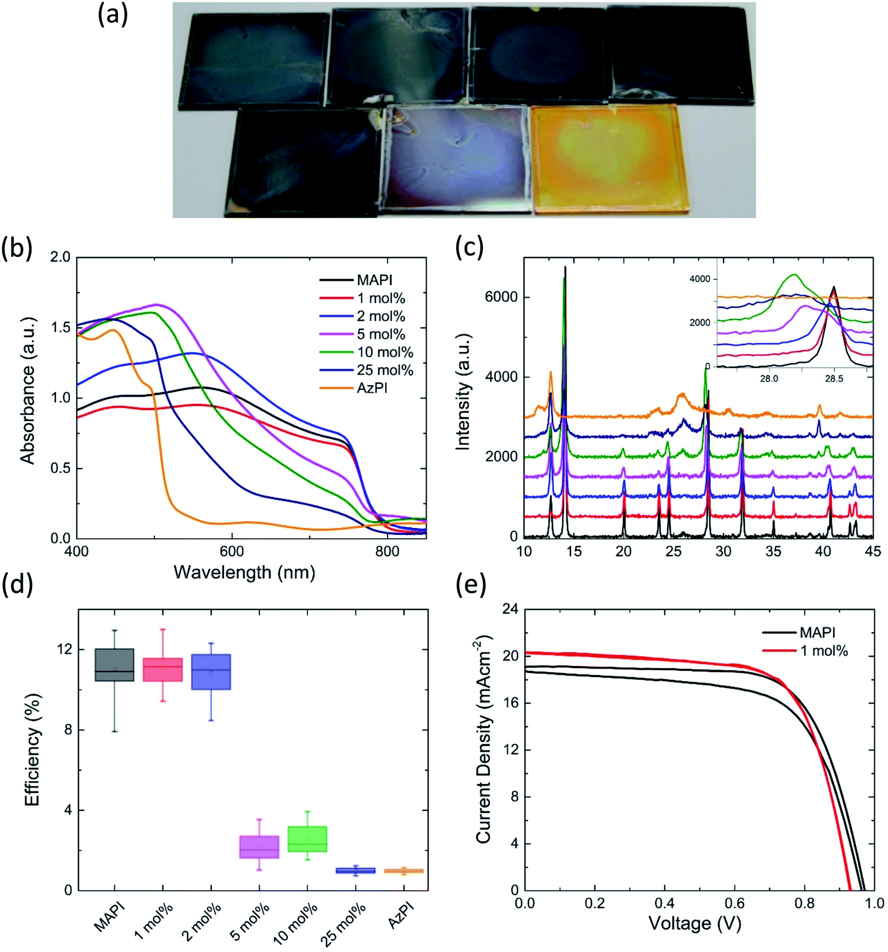 | ||
| Fig. 4 A study of the effects of azetidinium on methylammonium lead iodide (a) photographs of the AzMAPI films on glass with different mol% azetidinium iodide in the spin-coating solution, from left to right: (top row) MAPI, 1 mol% AzI, 2 mol% AzI, 5 mol% AzI; (bottom row) 10 mol% AzI, 25 mol% AzI and AzPI; (b) UV/Vis spectroscopy and (c) X-ray diffraction patterns for the films on glass with inset tracking of the movement of the (2, 2, 0) peak at 28.5°; (d) box-chart for the efficiencies of cells made using AzMAPI and (e) JV curves for the best performing MAPI and AzMAPI cells showing both the forward and reverse scan. | ||
In the powder X-ray diffraction pattern, derived from the thin film, there are clear trends that appear with the increasing mole percentage of azetidinium in the spin-coating solution. For compositional ratios of x ≤ 0.02, the diffraction pattern shifts towards smaller angles, caused by the increase in unit cell size. There is a single peak at 28.5° without shoulder, suggesting that there is a continuous phase of AzxMA1−xPbI3. AzMAPI crystals containing 1% and 5% Az+ were dissolved and characterised by NMR (Fig. S7†). It can be seen that peaks for Az are visible in the spectra.
To better understand the incorporation of Az+ into MAPI; the mixed A-cation lattice was simulated by randomly incorporating up to 5% Az+ cations in place of MA+ in the parent MAPI. The simulations show that a continuous phase can be formed and have allowed us to probe both the local structural effects and the energetics of substitution. First, we find significant local relaxation of the nearby PbI6 octahedra around the substituted Az+ cations as shown in Fig. 5, with displacements of neighbouring iodine ions of ∼0.3 Å. This assists in accommodating the larger cationic size of Az+ (2.5 Å) in comparison to MA+ (2.17 Å), while keeping the overall 3D perovskite structure.
 | ||
| Fig. 5 Simulated structure of AzMAPI using high level DFT methods. Local lattice relaxations in the Pb (green)/I (purple) framework near to the Az+ cations are highlighted by black circles. A zoomed image is available in Fig. S8.† | ||
Second, we explored the energetics of A-site cation mixing by evaluating the A-site substitution energy. The incorporation of Az+ into the MAPI perovskite lattice is found to be favourable (by 10 meV per formula unit). This result supports the experimental observation of easy incorporation of Az into the perovskite structure and suggests greater stability of the black perovskite phase of MAPI upon partial (≤5%) substitution of MA+ by Az+ cations. In addition, our calculations indicate that the band-gap does not change significantly with the incorporation of small amount of Az+ cations in MAPI. This finding is again in line with previous experimental observation of negligible PL-edge shift upon A-site cation mixing.
For larger Az ratios 0.05 ≤ x ≤ 0.1, the perovskite reflections indicate splitting into two domains. The primary AzPI peak at 26.2 appears at x = 0.1, and upon further increasing the Az ratio to x ≥ 0.25, the intensities of the MAPI phase reflections decrease, while the AzPI reflections become more intense. Taking the MAPI (2, 2, 0) reflection as an example (inset in Fig. 4c), there is a broadening and leftward shift – with the appearance of shoulders in the peak in the 5 mol% AzI sample. The apparent phase separations in the films made with a larger proportion of AzI explains the shape of the UV/Vis spectrum, with separate AzPI phases within the MAPI film causing shoulders in the absorbance, rather than completely shifting the band gap.
For solar cell fabrication PbI2 films were dipped into solutions of mixed AzI and MAI, to allow the organic cation solution to fully penetrate the mesoporous layer (Fig. S9†). MAPI cells were used as the control. Until recently the highest reported efficiency for a pure MAPI cell was 15%,2 however using a multi-step Lewis base adduct method, the efficiency can be increased to 19.7%.38 The highest efficiency devices are mixed cation and contain MA, FA and Cs. We chose to work with lower efficiency MAPI cells to allow us to fully characterise any changes introduced by the Az cations. The cells were made by a standard two-step deposition method and were not optimised for efficiency.
AzMAPI mixed cation cells deposited from a solution containing more than 5 mol% AzI show a lower efficiency than pure MAPI cells (Fig. 4d). This agrees with the UV/Vis spectra, XRD (Fig. 3b and c) and EQE (Fig. S10†) measurements which all show phase separation into MAPI and AzPI regions. A discontinuous phase may hinder charge transfer through the lattice. With lower percentages of azetidinium in solution there is an improvement in the average efficiency of the cells, which is largely due to an improved fill factor (Fig. S11†). This, as well as a significant reduction in the hysteresis, is evident in the JV curves displayed in Fig. 4e and S12,† where, as in Table 2, the best performing MAPI and AzMAPI pixels are compared. There is a reduction in the standard deviation of the cell efficiency, from 1.35 in the MAPI control to 0.95 in the Az0.01MA0.99PbI3 set. The stabilised power output of the devices also increased, shown in Fig. S13.† The best performing cell, from the Az0.01MA0.99PbI3 set had an efficiency of 13.00% in the reverse sweep, and 12.98% in the forward sweep.
| V OC (mV) | J SC (mA cm−2) | FF (%) | Champion cell (%) | Efficiency (%) | |
|---|---|---|---|---|---|
| MAPI | 948 ± 13 | 18.6 ± 0.70 | 62 ± 5.1 | 12.9 | 11.0 ± 1.35 |
| Az0.01MA0.99PI | 925 ± 16 | 18.1 ± 0.95 | 65 ± 4.0 | 13.0 | 11.1 ± 0.95 |
Conclusions
In conclusion, we have synthesised and characterised the new compound, azetidinium lead iodide (AzPI). We have determined that this compound exists as a stable, bright orange film and exhibits some photovoltaic capability, with an optical band gap of 2.15 eV. It is also possible that AzPI has a new structure that lies between a 2D and a 3D perovskite, but more structural characterisation needs to be carried out. Our work tests the application of tolerance factor calculations to these materials, as azetidinium lead iodide is predicted to be within the range for a 3D perovskite to form. Chemical differences in the cation itself (dipole, acidity of the N–H group) are likely to be a key factor that needs to be brought into consideration when making predictions. Azetidinium can be co-deposited with methylammonium to further improve the properties of the MAPI perovskite. These AzMAPI perovskites show an enhanced efficiency compared to pure MAPI, with a reduced hysteresis at low percentages of azetidinium.Conflicts of interest
There are no known conflicts of interest to declare.Acknowledgements
We thank the University of Bath (studentship for SRP), EPSRC Centre for Doctoral Training in New and Sustainable Photovoltaics (studentship for PSK under Grant EP/LO1551X/1) EPSRC Centre for Doctoral Training in Sustainable Chemical Technologies (studentship for FEJ under Grant EP/L016354/1), the EPSRC (PRR under grant EP/K004956 and PJC under grant EP/H026304/1), the European Union Seventh Framework Programme (RGN [FP7/2007–2013] (DESTINY project)) under grant agreement 316494 and the Horizon2020 programme (DG [EoCoE Project]) under grant agreement number 676629.Notes and references
- A. Kojima, K. Teshima, Y. Shirai and T. Miyasaka, J. Am. Chem. Soc., 2009, 131, 6050–6051 CrossRef CAS PubMed.
- J. Burschka, N. Pellet, S.-J. Moon, R. Humphry-Baker, P. Gao, M. K. Nazeeruddin and M. Grätzel, Nature, 2013, 499, 316–319 CrossRef CAS PubMed.
- C. Roldan-Carmona, P. Gratia, I. Zimmermann, G. Grancini, P. Gao, M. Graetzel and M. K. Nazeeruddin, Energy Environ. Sci., 2015, 8, 3550–3556 CAS.
- M. Liu, M. B. Johnston and H. J. Snaith, Nature, 2013, 501, 395–398 CrossRef CAS PubMed.
- A. Walsh, J. Phys. Chem. C, 2015, 119, 5755–5760 CAS.
- J. H. Noh, S. H. Im, J. H. Heo, T. N. Mandal and S. Il Seok, Nano Lett., 2013, 13, 1764–1769 CrossRef CAS PubMed.
- M. Yang, Y. Zhou, Y. Zeng, C.-S. Jiang, N. P. Padture and K. Zhu, Adv. Mater., 2015, 27, 6363–6370 CrossRef CAS PubMed.
- J. M. Frost, K. T. Butler, F. Brivio, C. H. Hendon, M. Van Schilfgaarde and A. Walsh, Nano Lett., 2014, 14, 2584–2590 CrossRef CAS PubMed.
- H.-S. Kim, C.-R. Lee, J.-H. Im, K.-B. Lee, T. Moehl, A. Marchioro, S.-J. Moon, R. Humphry-Baker, J.-H. Yum, J. E. Moser, M. Grätzel and N.-G. Park, Sci. Rep., 2012, 2, 591 CrossRef PubMed.
- F. Meillaud, A. Shah, C. Droz, E. Vallat-Sauvain and C. Miazza, Sol. Energy Mater. Sol. Cells, 2006, 90, 2952–2959 CrossRef CAS.
- F. Hao, C. C. Stoumpos, D. H. Cao, R. P. H. Chang and M. G. Kanatzidis, Nat. Photonics, 2014, 8, 489–494 CrossRef CAS.
- D. B. Mitzi, in Progress in Inorganic Chemistry, 2007, pp. 1–121 Search PubMed.
- A. Babayigit, D. Duy Thanh, A. Ethirajan, J. Manca, M. Muller, H.-G. Boyen and B. Conings, Sci. Rep., 2016, 6, 18721 CrossRef CAS PubMed.
- G. E. Eperon, S. D. Stranks, C. Menelaou, M. B. Johnston, L. M. Herz and H. J. Snaith, Energy Environ. Sci., 2014, 7, 982 CAS.
- J.-W. Lee, D.-J. Seol, A.-N. Cho and N.-G. Park, Adv. Mater., 2014, 6, 1–8 CrossRef.
- G. E. Eperon, G. M. Paterno, R. J. Sutton, A. Zampetti, A. A. Haghighirad, F. Cacialli and H. J. Snaith, J. Mater. Chem. A, 2015, 3, 19688–19695 CAS.
- R. G. Niemann, L. Gouda, J. Hu, S. Tirosh, R. Gottesman, P. J. Cameron and A. Zaban, J. Mater. Chem. A, 2016, 4, 17819–17827 CAS.
- J. P. C. Baena, L. Steier, W. Tress, M. Saliba, S. Neutzner, T. Matsui, F. Giordano, T. J. Jacobsson, A. R. S. Kandada, S. M. Zakeeruddin, A. Petrozza, A. Abate, M. K. Nazeeruddin, M. Grätzel and A. Hagfeldt, Energy Environ. Sci., 2015, 8, 2928–2934 Search PubMed.
- C. Yi, J. Luo, S. Meloni, A. Boziki, N. Ashari-Astani, C. Grätzel, S. M. Zakeeruddin, U. Rothlisberger and M. Grätzel, Energy Environ. Sci., 2015, 9, 656–662 Search PubMed.
- M. Saliba, T. Matsui, J.-Y. Seo, K. Domanski, J.-P. Correa-Baena, N. K. Mohammad, S. M. Zakeeruddin, W. Tress, A. Abate, A. Hagfeldt and M. Grätzel, Energy Environ. Sci., 2016, 9, 1989–1997 CAS.
- I. C. Smith, E. T. Hoke, D. Solis-Ibarra, M. D. McGehee and H. I. Karunadasa, Angew. Chem., 2014, 126, 11414–11417 CrossRef.
- N. De Marco, H. Zhou, Q. Chen, P. Sun, Z. Liu, L. Meng, E.-P. Yao, Y. Liu, A. Schiffer and Y. Yang, Nano Lett., 2016, 16, 1009–1016 CrossRef PubMed.
- H. Tsai, W. Nie, J.-C. Blancon, C. C. Stoumpos, R. Asadpour, B. Harutyunyan, A. J. Neukirch, R. Verduzco, J. J. Crochet, S. Tretiak, L. Pedesseau, J. Even, M. A. Alam, G. Gupta, J. Lou, P. M. Ajayan, M. J. Bedzyk, M. G. Kanatzidis and A. D. Mohite, Nature, 2016, 536, 312–316 CrossRef CAS PubMed.
- A. Amat, E. Mosconi, E. Ronca, C. Quarti, P. Umari, M. K. Nazeeruddin, M. Grätzel and F. De Angelis, Nano Lett., 2014, 14, 3608–3616 CrossRef CAS PubMed.
- C. C. Stoumpos, C. D. Malliakas and M. G. Kanatzidis, Inorg. Chem., 2013, 52, 9019–9038 CrossRef CAS PubMed.
- W. Travis, E. N. K. Glover, H. Bronstein, D. O. Scanlon and R. Palgrave, Chem. Sci., 2016, 7, 4548–4556 RSC.
- G. Kieslich, S. Sun and A. K. Cheetham, Chem. Sci., 2014, 5, 4712–4715 RSC.
- G. Kieslich, S. Sun and A. K. Cheetham, Chem. Sci., 2015, 6, 3430–3433 RSC.
- J. Brgoch, A. J. Lehner, M. L. Chabinyc and R. Seshadri, J. Phys. Chem. C, 2014, 18, 27721–27727 Search PubMed.
- A. F. Akbulatov, L. A. Frolova, D. A. Anokhin, K. L. Gerasimov, N. N. Dremova and P. Troshin, J. Mater. Chem. A, 2016, 4, 18378–18382 CAS.
- W. Travis, E. N. K. Glover, H. Bronstein, D. O. Scanlon and R. Palgrave, Chem. Sci., 2016, 7, 4548–4556 RSC.
- M. Becker, T. Kluner and M. Wark, Dalton Trans., 2017, 46, 3500–3509 RSC.
- B. Zhou, Y. Imai, A. Kobayashi, Z.-M. Wang and H. Kobayashi, Angew. Chem., Int. Ed., 2011, 50, 11441–11445 CrossRef CAS PubMed.
- I. C. Smith, E. T. Hoke, D. Solis-Ibarra, M. D. McGehee and H. I. Karunadasa, Angew. Chem., 2014, 126, 11414–11417 CrossRef.
- H. Zheng, W. Wang, S. Yang, Y. Liu and J. Sun, RSC Adv., 2016, 6, 1611–1617 RSC.
- R. Dutler, A. Rauk and R. A. Shaw, J. Phys. Chem., 1990, 94, 118–124 CrossRef CAS.
- T. M. Koh, K. Fu, Y. Fang, S. Chen, T. C. Sum, N. Mathews, S. G. Mhaisalkar, P. P. Boix and T. Baikie, J. Phys. Chem. C, 2014, 118, 16458–16462 CAS.
- N. Ahn, D.-Y. Son, I.-H. Jang, S. M. Kang, M. Choi and N.-G. Park, J. Am. Chem. Soc., 2015, 137, 8696–8699 CrossRef CAS PubMed.
- C. Ma, C. Leng, Y. Ji, X. Wei, K. Sun, L. Tang, J. Yang, W. Luo, C. Li, Y. Deng, S. Feng, J. Shen, S. Lu, C. Du and H. Shi, Nanoscale, 2016, 338, 643–647 Search PubMed.
- K. Yao, X. Wang, F. Li and L. Zhou, Chem. Commun., 2015, 51, 15430–15433 RSC.
Footnote |
| † Electronic supplementary information (ESI) available. See DOI: 10.1039/c7ta07545f |
| This journal is © The Royal Society of Chemistry 2017 |