
 Open Access Article
 This Open Access Article is licensed under a
 Creative Commons Attribution 3.0 Unported Licence
Structural lithium ion battery electrolytes via reaction induced phase-separation†
N.
Ihrner
 a,
W.
Johannisson
b,
F.
Sieland
c,
D.
Zenkert
b and
M.
Johansson
*a
a,
W.
Johannisson
b,
F.
Sieland
c,
D.
Zenkert
b and
M.
Johansson
*a
aDepartment of Fibre and Polymer Technology, School of Chemical Sciences and Engineering, KTH Royal Institute of Technology, 100 44 Stockholm, Sweden. E-mail: matskg@kth.se
bDepartment of Aeronautical and Vehicle Engineering, School of Engineering Sciences, KTH Royal Institute of Technology, 100 44 Stockholm, Sweden
cUniversity of Paderborn, Faculty of Science, Department of Chemistry, Warburger Straße 100, 33098 Paderborn, Germany
First published on 24th November 2017
Abstract
For the realization of structural batteries, electrolytes where both higher ionic conductivity and stiffness are combined need to be developed. The present study describes the formation of a structural battery electrolyte (SBE) as a two phase system using reaction induced phase separation. A liquid electrolyte phase is combined with a stiff vinyl ester based thermoset matrix to form a SBE. The effect of monomer structure variations on the formed morphology and electrochemical and mechanical performance has been investigated. An ionic conductivity of 1.5 × 10⁻⁴ S cm−1, with a corresponding storage modulus (E′) of 750 MPa, has been obtained under ambient conditions. The SBEs have been combined with carbon fibers to form a composite lamina and evaluated as a battery half-cell. Studies on the lamina revealed that both mechanical load transfer and ion transport are allowed between the carbon fibers and the electrolyte. These results pave the way for the preparation of structural batteries using carbon fibers as electrodes.
1. Introduction
Structural batteries have evolved as one possible route to enhance the system performance of lithium ion (Li-ion) batteries in vehicle applications addressing future demand for more efficient systems.1,2 A structural battery should have sufficient mechanical performance to allow it to be an integrated part in a device or a vehicle and thus not only contribute with energy storage but also be a part of the structure.3 From a materials point of view one could state that the materials should exhibit multi-functionality, i.e., have two or more inherently different properties optimized towards an end-use application. Today's Li-ion batteries basically consist of two electrodes, two current collectors, a separator, a lithium source, and electrolyte where the electrolyte/separator should allow for high ionic conductivity and be electrically insulating.4 For the realization of a structural battery the electrodes have to be able to carry a mechanical load, while simultaneously providing Li-ion intercalation, i.e., function as an electrode. The electrodes should preferably also be able to conduct electricity; this would eliminate the need for current collectors and lead to additional weight savings.In today's Li-ion batteries graphite is used as the negative electrode due to its ability to intercalate Li ions. A suitable alternative electrode material in this context would be carbon fibers, which show some resemblance to graphite. Carbon fibers are made by high temperature pyrolysis of a fiber precursor that during this process forms various carbon allomorphs such as graphite sheets and semi-amorphous regions.5 Carbon fibers are state-of-the-art reinforcement in composites and show excellent mechanical properties; moreover they are electrically conductive and readily intercalate Li ions.6,7 Carbon fibers exhibit great multi-functionality and are therefore good candidates as electrodes in structural battery applications.
To fully utilize the loadbearing potential of carbon fibers, they need to be combined with a suitable matrix (electrolyte) that exhibits both Li-ion conduction and load transfer. However the demand for high Li-ion mobility in the electrolyte has traditionally led to the utilization of liquid electrolytes.8 A disadvantage of liquids is that they cannot transfer load and a casing is required for containment and protection. One solution to this is solid polymer electrolytes (SPEs) or gel polymer electrolytes (GPEs) where the electrolyte is a soft solid rather than a liquid to minimize leakage issues as well as providing improved shape retention.9 The majority of studies on SPEs have employed thermoset polymers with polyethylene glycol (PEG) segments in the structure to coordinate Li ions and improve the ionic conductivity.10–12 It has been shown that when the crystallization of PEG segments is suppressed, they can dissolve lithium salts well and provide chain mobility to yield reasonably good ionic conductivities.13–15 Nevertheless, there is still a direct relationship between the mechanical properties and the ionic conductivity, i.e., the stiffer these SPEs become, the less conductive they are.16–18 A typical crosslinked PEG based electrolyte with an E-modulus of 100 MPa exhibits a corresponding ionic conductivity in the range of 10−6 S cm−1.16–19 This conductivity is significantly lower than that of a liquid electrolyte which can be in the order of 10−2 S cm−1 at ambient temperature.8 One route to enhance the ionic conductivity is to use a solvent, thereby plasticizing the polymer system and forming a gel polymer electrolyte (GPE).20 Although this can increase the ionic conductivity significantly, with some GPE systems reaching ionic conductivities of ∼10−2 S cm−1,21 the mechanical properties are drastically reduced, and thus they cannot be used in a structural battery. Studies on ternary mixtures of photo-polymerized PEG-diacrylates combined with a solid plasticizer and a lithium salt have resulted in fully amorphous solvent-free solid membranes with conductivities reaching 3 × 10⁻² S cm−1.22
Another approach is to introduce a two-phase system on the sub-micron scale. It has for example been demonstrated that a significant enhancement of the multifunctional properties can be achieved by using nano-sized reinforcement of the electrolyte such as nano-cellulose as described by Willgert et al.23 Shirshova et al. utilized carbon aerogels incorporated into a matrix to enhance both the electrical and mechanical performance.24 Another approach to enhance the performance of a structural battery electrolyte is to create a phase-separated system with two continuous amorphous phases where one provides ionic conductivity and the other mechanical integrity. This approach has been demonstrated via several routes using either vinyl ester or epoxy systems combined with either traditional electrolyte solvents or ionic liquids.25–30 Lodge et al. developed the concept of polymerization induced phase separation (PIPS) to form membranes with two bis-continuous phases allowing for both high ionic conductivity and mechanical strength.31,32 A wide range of combinations of ionic liquids, lithium salts, PEG segments, crosslinked polystyrene, and solid plasticizers has been used to demonstrate the versatility of this approach. Although several systems perform reasonably well, most systems containing ionic liquids suffer from low Li-ion transference numbers which may lead to concentration overpotentials in battery applications.33
The present paper describes a further extension of the concept of using reaction induced phase separation to prepare phase-separated structural battery electrolytes (SBEs). A SBE should not only perform well as a free standing membrane but must also connect to the reinforcing carbon fiber electrode to allow for simultaneous mechanical load transfer and ion transport. The concept of reaction induced phase separation is based on the fact that a polymer has different solubility parameters than the monomers used to produce it. By using solvents that are miscible with the monomers but not the resulting polymer, a reaction induced phase separation can be induced during polymerization. The concept of using reaction induced phase separation to form a structural battery electrolyte presents a number of advantages when proceeding towards a final structural battery using carbon fibers as electrodes. The main advantage is that by having a homogeneous low viscous liquid prior to curing, the solution can be vacuum-infused onto the carbon fibers and then directly cured in a one-step reaction. A reaction induced phase separation also allow for a homogenous electrolyte to be formed on a macroscopic level.
In this study a series of SBEs with different degrees of crosslinking and amount of liquid electrolyte are prepared via reaction induced phase separation. The morphology and mechanical and electrochemical properties of the SBEs are characterized and as a final step a carbon fiber laminate half-cell is prepared and cycled using Li-metal foil as a counter electrode. The final SBEs exhibit a significant improvement with respect to both ionic conductivity and modulus compared to earlier non-phase-separated SPE systems.
2. Experimental
2.1 Materials used
The chemical structures of the monomers, solvents and lithium salt used can be seen in Fig. 1. Bisphenol A dimethacrylate (A; M = 364.43 g mol−1), bisphenol A ethoxylate dimethacrylate (B; Mn = 540 g mol−1), dimethyl methylphosphonate (97%) (DMMP), ethylene carbonate (99% anhydrous) (EC), and lithium trifluoromethanesulfonate (LiTFS) (96%) were purchased from Sigma-Aldrich. 2,2-Dimethoxy-2-phenylacetophenone (DMPA) was obtained from BASF. Carbon fibers of the type T800HB-6000-40 were purchased from Toray Industries Inc. All materials were used as received. | ||
| Fig. 1 Chemical structures of the chemicals used in the study: monomers A and B, solvents EC and DMMP and the LiTFS salt. | ||
2.2 Techniques & procedures
![[thin space (1/6-em)]](https://www.rsc.org/images/entities/char_2009.gif) :50) wt%). LiTFS was then dissolved until a concentration of 1.0 M was reached. The liquid electrolyte was then mixed with monomer A and/or B and the UV-initiator, DMPA, in the amounts listed in Table 1.
:50) wt%). LiTFS was then dissolved until a concentration of 1.0 M was reached. The liquid electrolyte was then mixed with monomer A and/or B and the UV-initiator, DMPA, in the amounts listed in Table 1.
| Sample | A (g) | B (g) | 1.0 M LiTFS in EC:DMMP (g) |
DMPA (g) |
|---|---|---|---|---|
| A/0.60 | 1 | 0 | 0.60 | 0.01 |
| A/0.65 | 1 | 0 | 0.65 | 0.01 |
| AB/0.60 | 0.5 | 0.5 | 0.60 | 0.01 |
| AB/0.65 | 0.5 | 0.5 | 0.65 | 0.01 |
| B/0.60 | 0 | 1 | 0.60 | 0.01 |
| B/0.65 | 0 | 1 | 0.65 | 0.01 |
Samples containing monomer A were heated to approximately 80 °C to melt the crystalline monomer. The sample mixtures were then transferred to an aluminum mold (30 × 6 × 0.6 mm) and UV-cured, with a total dose of 1.2 J cm−2. Samples containing monomer B were cured at ambient temperature while samples consisting solely of monomer A were UV-cured at approximately 60 °C, to prevent monomer A from recrystallizing. A Blak Ray B100-AP (100 W, 365 nm) Hg UV lamp with an intensity of 5.2 mW cm−2 was used as a light source for 4 minutes. The intensity was determined with a Uvicure Plus High Energy UV Integrating Radiometer (EIT, USA), measuring UVA at 320–390 nm.
:DMMP. The samples were then dried in a vacuum oven; afterwards, they were weighed to determine the mass loss before studying them under the SEM. The samples were cooled in liquid nitrogen and then fractured to expose the cross-section. The fractured samples were coated with Pt/Pd using an Agar HR sputter coater; a sputtered layer thickness of 3 nm was chosen.
:DMMP were used to guarantee contact between the lithium metal foil and the carbon fiber lamina half-cell.
3. Results & discussion
3.1 System description
The system used in the present study is based on methacrylate functionalized bisphenol A based resin (monomers A and B). The difference between monomers A and B is that the latter contains PEG segments making monomer B slightly more polar. Monomer B will furthermore produce a less densely crosslinked network, subsequently yielding lower Tg. The system further comprises a lithium salt (LiTFS) and a combination of two solvents, EC and DMMP, with suitable solubility parameters.34 It should be noted here that the solvent/lithium salt mixture is a highly polar electrolyte and that the monomer although miscible with the electrolyte is significantly less polar. Three different thermoset resins, with different degrees of rigidity, have been evaluated varying the amount of solvent and LiTFS as presented in Table 1.3.2 Curing performance
The curing performance differs between the different monomer compositions (see Fig. 2). System B reaches the highest conversion, around 95%, while the samples containing monomer A reach lower conversion, system AB around 82% and system A around 60%. The reason for the higher conversion of system B is the lower ultimate Tg compared to systems A and AB. Fully cured systems A and AB potentially have a very high Tg and when the polymerization is performed at ambient or slightly elevated temperature, as in the present case, then vitrification effects are the limiting factor to obtaining high double bond conversion.35 Residual unsaturations may be detrimental to the long term performance of a battery, which is why this needs to be addressed when choosing the curing conditions. Using photopolymerization under ambient conditions is thus a limiting factor when aiming for high Tg systems. Further development of the process is however beyond the scope of the present paper. | ||
| Fig. 2 FT-IR spectra of samples A/0.65, AB/0.65 and B/0.65 between 1550 and 2000 cm−1. The circumscribed part shows the vinyl stretching peak at 1637 cm−1. | ||
3.3 SBE microstructure
The phase separation is affected by several parameters including ingoing components, relative solubility parameters between ingoing components, reaction temperature and reaction kinetics. It was not fully clear how these different parameters correlate with each other, which is why an investigation of the formed SBE morphology was carried out. Data on the calculated solubility parameters are provide in the ESI for guidance (Table S1†). It was visually seen that the systems clearly differed with respect to transparency going from a clear SBE (system B) to a more opaque appearance for system AB, and finally a white appearance for system A, as seen in Fig. 3. This implies that the phase separation increases in domain size from a nano scale for system B to a micron scale for system A, since the opacity mainly relates to the scattering of visible light. | ||
| Fig. 3 Visual appearance of samples A/0.60, AB/0.60 and B/0.60. Typical appearance of samples used in the DMA and EIS measurements. | ||
The SEM images (Fig. 4) corroborate visual observations that the microstructure differs in length scale with system B having the smallest pores in the range of 50–100 nm. The difference can be attributed to the difference in chemical structure, where monomer B is proposed to be slightly more compatible with the liquid electrolyte; this is due to the extra ethylene glycol units between the two methacrylate groups. This means that the phase separation occurs at a later stage where molecular mobility is more restricted due to constraints imposed by the formation of a network. It should furthermore be noted that all samples reveal a relatively homogeneous structure on a macro scale, i.e., no gradients were detected on a visual basis. This is important since any gradients would be detrimental either to the mechanical or the electrochemical performance of the SBE. The SEM results furthermore corroborate the electrochemical measurements described below.
 | ||
| Fig. 4 SEM images of samples (top to bottom) A/0.65, AB/0.65 and B/0.65 at 35k magnification. The liquid electrolyte has been extracted beforehand in all samples. | ||
Gravimetric analysis, see Table 2, of the samples prepared for the SEM analysis furthermore reveals that an almost complete removal of the lithium salt and solvent can be achieved by a simple washing and drying procedure. These results strongly indicate that a percolating structure has been obtained in all cases with a very low level of isolated and confined solvent and lithium ion inclusions present. FTIR analysis of the solvent/lithium salt, the as-prepared SBE, and finally the washed and dried SBE also supports these findings (Fig. S1–S6†).
| Sample | σ (S cm−1) | E′, 25 °C (MPa) | T g (°C) | Sample weight loss after washing (%) |
|---|---|---|---|---|
|
a Selected as the top of the tanδ peak.
|
||||
| A/0.60 | 1.5 × 10⁻⁴ | 750 | — | 34 |
| A/0.65 | 2.1 × 10⁻⁴ | 530 | — | 35 |
| AB/0.60 | 1.1 × 10⁻⁴ | 730 | — | 37 |
| AB/0.65 | 1.9 × 10⁻⁴ | 550 | — | 36 |
| B/0.60 | 1.2 × 10⁻⁴ | 380 | 71 | 37 |
| B/0.65 | 2.0 × 10⁻⁴ | 360 | 72 | 39 |
3.4 Mechanical and electrochemical performance of the SBE
The results from the mechanical tests reveal that all samples exhibit significantly different behavior. Samples B/0.60 and 0.65 have a broad but well defined Tg transition at around 70 °C (tanδ peak) while samples A/0.60 and 0.65 and AB/0.60 and 0.65 have wider and higher Tg transitions (Fig. 5a). No clear Tg can be seen for samples A/0.60 and 0.65 and AB/0.60 and 0.65 but rather a gradual decay in modulus which is common for highly crosslinked rigid thermosets (see Fig. 5b). It is also known that post-curing can happen during the heating ramp for these systems if vitrification35 has occurred during crosslinking; this could be the reason for the difference between samples A/0.60 and 0.65 and AB/0.60 and 0.65 at higher temperatures. Overall it is proposed that there are several reasons for these differences, starting with the intrinsic difference in monomer structure. Monomer A (in systems A and AB) should give both a higher modulus and Tg due to the higher crosslink density and less aliphatic character of the monomer. Samples B/0.60 and 0.65 however have reached higher conversion which should increase the Tg. A third factor that will have an influence is the potential softening effect of the rigid phase if either the solvent or the lithium salt to a small extent still remains in the polymer phase and this is more likely in samples B/0.60 and 0.65. This latter factor is also supported by a slightly lower modulus for samples B/0.60 and 0.65 below Tg as listed in Table 2.
 | ||
| Fig. 5 (a) Tanδ vs. temperature and (b) storage modulus E′ vs. temperature for samples A/0.65, AB/0.65 and B/0.65. | ||
The ionic conductivities of the three systems are nearly equal, which supports the view that the extent of the phase separation is comparable for all three systems and that the difference in size of the phase separation has little to no effect on the ionic conductivity (Fig. 6). This is in contrast to previous findings by Shirshova et al.,24 who reported a distinct effect of the size of the ionic domains on the ionic conductivity. These systems were however based on ionic liquids as one component whereas the present system has a neutral solvent combined with lithium salt indicating that the relationship between domain size and ionic conductivity is very system dependent. The ionic conductivity as a function of temperature is also very similar for the three different systems, which further strengthens the conclusion that the polymer phase has little effect on the ionic conductivity of the SBE. The conductivity for all systems increases with temperature increasing from room temperature up to 100 °C, which is normal for a traditional liquid electrolyte (Fig. S7†). The ionic conductivity in the present study increases with increasing solvent content; it is nearly doubled in all three systems when 0.65 g (39 wt%) of liquid electrolyte instead of 0.60 g (37 wt%) is used (Fig. 6). This large increase in conductivity indicates that these specific compositions could be close to the percolation thresholds for the systems although a much more detailed study is needed to confirm this. Although the increase in ionic conductivity remains similar for the systems, the change in mechanical properties does not. In sample B/0.65 the decrease in E′ is much smaller (5%) compared to samples A/0.65 and AB/0.65 (29% and 25%). In sample A/0.65 the brittleness is significantly increased and the addition of more liquid electrolyte leads to sample fracturing during characterization. Samples that incorporate monomer B have lower degrees of crosslinking and thereby greater flexibility compared to samples A/0.60 and 0.65. The lower degree of crosslinking increases the amount of solvent that can be incorporated and thereby the ionic conductivity; however the lower degree of crosslinking leads to a lower intrinsic E′ of the material and the more crosslinked sample might be preferable when both ionic conductivity and E′ are taken into consideration.
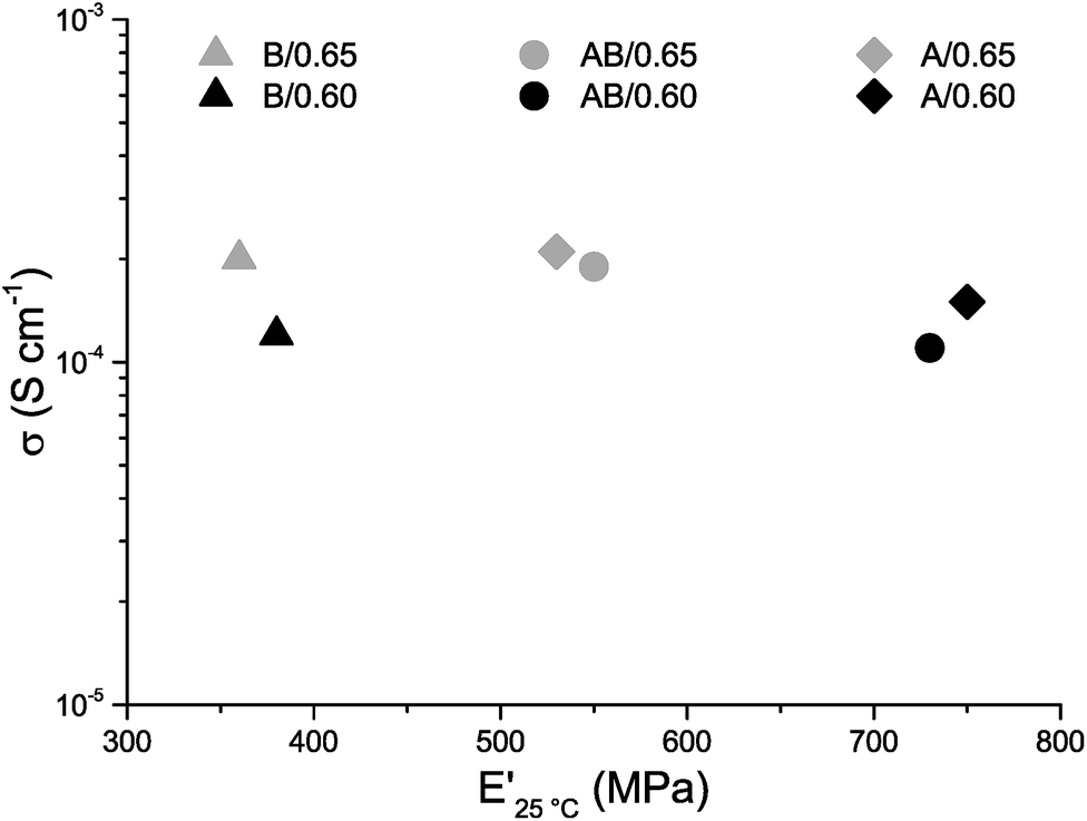 | ||
| Fig. 6 Ionic conductivity σ (logarithmic scale) vs. storage modulus E′ for samples A/0.60, AB/0.60, B/0.60, A/0.65, AB/0.65 and B/0.65. | ||
3.5 Evaluation of the SBE carbon fiber lamina half-cell
A lamina half-cell was made utilizing SBE system AB/0.65 together with carbon fibers to demonstrate the ability of the SBE to provide multifunctionality in an integrated structure. The infusion of the fiber bundle with system AB/0.65 was easily achieved due to the system's low viscosity and homogeneous character. This is an important feature when considering the production of future structural batteries using conventional composite production techniques such as resin infusion. The cured SBE/carbon fiber lamina specimen retained its structural integrity to form a composite structure (see Fig. 7). Fig. 7 shows the lithiation and delithiation curves for the 1st, 2nd, and 10th cycles for the carbon fiber lamina half-cell utilizing lithium metal foil as the counter electrode. The successful electrochemical cycling of the carbon fiber lamina half-cell demonstrates that the interface formed between the matrix and carbon fibers allows Li-ion transport and that Li ions are transported through the SBE matrix. The cell shows a high drop in capacity for the first cycle, which is normal for Li-ion batteries. This drop corresponds to the formation of an SEI layer on the carbon fiber36,37 as well as the trapping of Li ions in the carbon fiber microstructure during the first cycle.38 The voltage profile looks very similar to those obtained in studies on other carbon fibers cycled in a liquid electrolyte, indicating that there are no large side reactions with the present SBE compared to a liquid electrolyte.6 The cycling behaviour is almost on par with carbon fiber cycled with state-of-the-art liquid electrolytes, such as that shown by M. H. Kjell et al.,6 considering that only 39% (w/w) of the SBE is actually an electrolyte with 61% (w/w) being the rigid thermoset phase with negligible ionic conductivity. Additional cycling tests at a rate of C/5 on sample AB/0.65 after the formation cycles show a good cycling stability up to 50 cycles (Fig. S8†). The mechanical testing provided an elastic modulus for the SBE film of 730 MPa and a transverse elastic modulus of the carbon fiber lamina half-cell of 3.1 GPa, confirming that the SBE matrix has attached to the carbon fiber surfaces. The combined results of structural integrity and electrochemical performance demonstrate that the present SBE in combination with carbon fibers exhibits a truly multifunctional performance. Detailed investigation into the interfacial characteristics of the composite and a more extensive electrochemical and mechanical performance is a subject for further studies.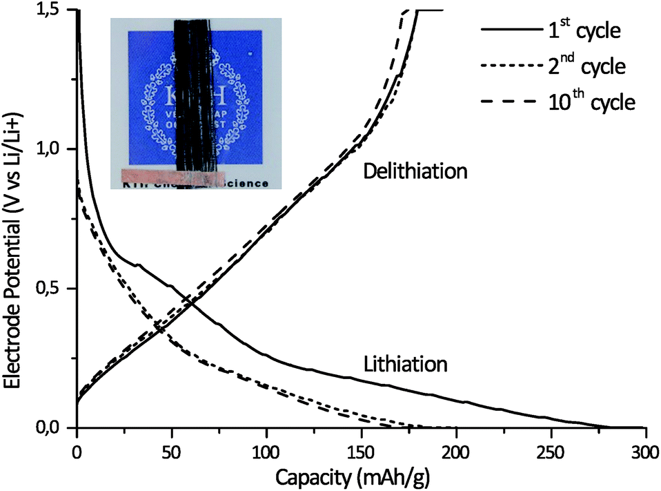 | ||
| Fig. 7 Lithiation and delithiation curves for the carbon fiber composite half-cell, at C/20 for the 1st, 2nd and 10th cycles. The inset is a photograph of a typical sample used for the cycling experiments. | ||
4. Conclusions
A series of two phase SBEs, combining a liquid phase and a stiff polymer thermoset phase, where the different phases are percolating throughout the SBE have successfully been made using reaction induced phase separation. The domain size of the phase separation and the morphology of the SBEs can be tailored, by changing the monomer structure as well as the ratio between the monomers, to range from an opaque micron scale phase separation to a fully transparent nanoscale phase separation. The SBEs can furthermore be combined with carbon fibers to form a lamina half-cell with both structural integrity and ionic conductivity. Combining the results from the mechanical and conductivity measurements, it is seen that, at ambient temperature, all SBEs exhibit good ionic conductivity in combination with high E′ on a level that allows truly structural batteries to be made.Conflicts of interest
There are no conflicts to declare.Acknowledgements
The authors would like to thank the Swedish Energy Agency for providing the funding for this project, grant #37712-1 “Structural batteries for efficient vehicles”. The entire research group within the program is acknowledged for valuable discussion and input on this work.Notes and references
- E. D. Wetzel, AMPTIAC Q., 2004, 8, 91–95 CAS.
- J. P. Thomas and M. A. Qidwai, JOM, 2005, 57, 18–24 CrossRef CAS.
- L. E. Asp and E. S. Greenhalgh, Compos. Sci. Technol., 2014, 101, 41–61 CrossRef CAS.
- K. Ozawa, Lithium Ion Rechargeable Batteries: Materials, Technology, and New Applications, WILEY-VCH, Weinheim, 2009 Search PubMed.
- J. B. Donnet and R. C. Bansal, Carbon Fibers, 3rd edn, Taylor & Francis, 1998 Search PubMed.
- M. H. Kjell, E. Jacques, D. Zenkert, M. Behm and G. Lindbergh, J. Electrochem. Soc., 2011, 158, A1455–A1460 CrossRef CAS.
- E. Jacques, M. H. Kjell, D. Zenkert, G. Lindbergh, M. Behm and M. Willgert, Compos. Sci. Technol., 2012, 72, 792–798 CrossRef CAS.
- K. Xu, Chem. Rev., 2004, 104, 4303–4418 CrossRef CAS PubMed.
- J. W. Fergus, J. Power Sources, 2010, 195, 4554–4569 CrossRef CAS.
- H. Cheradame, J. L. Souquet and J. M. Latour, Mater. Res. Bull., 1980, 15, 1173–1177 CrossRef CAS.
- J.-F. L. Nest, A. Gandini and H. Cheradame, Br. Polym. J., 1988, 20, 253–268 CrossRef.
- J. F. Snyder, E. D. Wetzel and C. M. Watson, Polymer, 2009, 50, 4906–4916 CrossRef CAS.
- D. E. Fenton, J. M. Parker and P. V. Wright, Polymer, 1973, 14, 589 CrossRef CAS.
- P. V. Wright, Br. Polym. J., 1975, 7, 319–327 CrossRef CAS.
- M. Armand, Solid State Ionics, 1983, 9–10, 745–754 CrossRef CAS.
- J. F. Snyder, R. H. Carter and E. D. Wetzel, Chem. Mater., 2007, 19, 3793–3801 CrossRef CAS.
- M. Willgert, M. H. Kjell, E. Jacques, M. Behm, G. Lindbergh and M. Johansson, Eur. Polym. J., 2011, 47, 2372–2378 CrossRef CAS.
- N. Ihrner and M. Johansson, J. Appl. Polym. Sci., 2017, 134(23) DOI:10.1002/app.44917.
- M. Willgert, M. H. Kjell, G. Lindbergh and M. Johansson, Solid State Ionics, 2013, 236, 22–29 CrossRef CAS.
- Z. Xue, D. He and X. Xie, J. Mater. Chem. A, 2015, 3, 19218–19253 CAS.
- A. Manuel Stephan, Eur. Polym. J., 2006, 42, 21–42 CrossRef CAS.
- M. Echeverri, C. Hamad and T. Kyu, Solid State Ionics, 2014, 254, 92–100 CrossRef CAS.
- M. Willgert, S. Leijonmarck, G. Lindbergh, E. Malmstrom and M. Johansson, J. Mater. Chem. A, 2014, 2, 13556–13564 CAS.
- N. Shirshova, H. Qian, M. Houlle, J. H. G. Steinke, A. R. J. Kucernak, Q. P. V. Fontana, E. S. Greenhalgh, A. Bismarck and M. S. P. Shaffer, Faraday Discuss., 2014, 172, 81–103 RSC.
- N. Shirshova, A. Bismarck, S. Carreyette, Q. P. V. Fontana, E. S. Greenhalgh, P. Jacobsson, P. Johansson, M. J. Marczewski, G. Kalinka, A. R. J. Kucernak, J. Scheers, M. S. P. Shaffer, J. H. G. Steinke and M. Wienrich, J. Mater. Chem. A, 2013, 1, 15300–15309 CAS.
- M. W. Schulze, L. D. McIntosh, M. A. Hillmyer and T. P. Lodge, Nano Lett., 2014, 14, 122–126 CrossRef CAS PubMed.
- N. Shirshova, A. Bismarck, E. S. Greenhalgh, P. Johansson, G. Kalinka, M. J. Marczewski, M. S. P. Shaffer and M. Wienrich, J. Phys. Chem. C, 2014, 118, 28377–28387 CAS.
- E. B. Gienger, P.-A. T. Nguyen, W. Chin, K. D. Behler, J. F. Snyder and E. D. Wetzel, J. Appl. Polym. Sci., 2015, 132(42) DOI:10.1002/app.42681.
- E. Greenhalgh, J. Ankersen, L. Asp, A. Bismarck, Q. Fontana, M. Houlle, G. Kalinka, A. Kucernak, M. Mistry, S. Nguyen, H. Qian, M. Shaffer, N. Shirshova, J. Steinke and M. Wienrich, J. Compos. Mater., 2015, 49, 1823–1834 CrossRef CAS.
- Y. Yu, B. Zhang, Y. Wang, G. Qi, F. Tian, J. Yang and S. Wang, Mater. Des., 2016, 104, 126–133 CrossRef CAS.
- L. D. McIntosh, M. W. Schulze, M. T. Irwin, M. A. Hillmyer and T. P. Lodge, Macromolecules, 2015, 48, 1418–1428 CrossRef CAS.
- S. A. Chopade, J. G. Au, Z. Li, P. W. Schmidt, M. A. Hillmyer and T. P. Lodge, ACS Appl. Mater. Interfaces, 2017, 9, 14561–14565 CAS.
- A. Lewandowski and A. Świderska-Mocek, J. Power Sources, 2009, 194, 601–609 CrossRef CAS.
- C. M. Hansen, Hansen Solubility Parameters: A User's Handbook, 2nd edn, CRC Press, 2007 Search PubMed.
- T. Glauser, M. Johansson and A. Hult, Macromol. Mater. Eng., 2000, 274, 25–30 CrossRef CAS.
- E. Peled, J. Electrochem. Soc., 1979, 126, 2047–2051 CrossRef CAS.
- D. Aurbach, B. Markovsky, M. D. Levi, E. Levi, A. Schechter, M. Moshkovich and Y. Cohen, J. Power Sources, 1999, 81–82, 95–111 CrossRef CAS.
- J. Hagberg, S. Leijonmarck and G. Lindbergh, J. Electrochem. Soc., 2016, 163, A1790–A1797 CrossRef CAS.
Footnote |
| † Electronic supplementary information (ESI) available. See DOI: 10.1039/c7ta04684g |
| This journal is © The Royal Society of Chemistry 2017 |