 Open Access Article
Creative Commons Attribution 3.0 Unported Licence
High performance carbon-based printed perovskite solar cells with humidity assisted thermal treatment†
Syed Ghufran
Hashmi
 *a,
David
Martineau
b,
M. Ibrahim
Dar
c,
Teemu T. T.
Myllymäki
 d,
Teemu
Sarikka
e,
Vainio
Ulla
d,
Shaik Mohammed
Zakeeruddin
c and
Michael
Grätzel
c
d,
Teemu
Sarikka
e,
Vainio
Ulla
d,
Shaik Mohammed
Zakeeruddin
c and
Michael
Grätzel
c
aNew Energy Technologies Group, Department of Applied Physics, Aalto University, P. O. Box 15100, FI-00076 Aalto, Espoo, Finland. E-mail: ghufran.hashmi@aalto.fi; sghufranh28@gmail.com
bSolaronix SA, Rue de l' Ouriette 129, CH-1170 Aubonne, Switzerland
cLaboratory of Photonics and Interfaces, Ecole Polytechnique Federale de Lausanne (EPFL), CH G1 551, Station 6, CH-1015 Lausanne, Switzerland
dDepartment of Applied Physics, Aalto University, P.O. Box 15100, FI-00076 Aalto, Finland
eDepartment of Mechanical Engineering, Aalto University School of Engineering, 14100, FI-00076, Otakaari 4 (K1), 02150 Espoo, Finland
First published on 22nd May 2017
Abstract
We report humidity assisted thermal exposure (HTE) as a post-treatment method for carbon based printed perovskite solar cells (CPSCs). The method does not only improve the interfaces of different layers of the printed stack, but also provides a pathway to fabricate high performance CPSCs with low hysteresis along with high stability. The HTE treatment directly influences over the associated components in the stack and remarkably improves each photovoltaic parameter of the CPSCs as seen by several characterization schemes presented in this study. The average initial efficiency (9.0% ± 0.2%) of the CPSCs of a batch was significantly improved to 13.1% ± 0.2% i.e. as high as 45% when subjected to HTE treatment for a period of 200 hours. Furthermore, the highest average efficiency obtained from the same batch from reverse scanning was 13.8% ± 0.4% with a CPSC attaining as high as 14.3% when exposed to the same thermo-humid environment for a period of 115 hours. Above all, the stability of the HTE treated CPSCs was also not compromised for over 350 hours under full-sun illumination stress testing at 40 °C. The results presented in this work provide an opportunity to adopt HTE treatment as a complementary step for the fabrication of high-performance carbon-based perovskite solar cells with low hysteresis accompanied by high durability and performance reproducibility.
Organic–Inorganic lead halide perovskite based solar cells (PSCs) have recently exhibited very high efficiencies (>22%) in their traditional device structures,1 thus showing potential to compete with other commercialized photovoltaic (PV) technologies, such as cadmium telluride (CdTe, 22.1%), multi-crystalline Si (c-Si, 21.3%) or copper indium gallium selenide (CIGS, 22.3%) solar cells, along with their rapid energy payback time.2,3 Nevertheless, poor long-term stability and costly materials (i.e. high purity Spiro-OMeTAD approximately costs 200–400 $ per g) along with expensive manufacturing methods and high lead (Pb) wastage are the biggest challenges in the commercialization of these traditional PSCs technologies.4–7 Therefore, several alternative device structures have been explored by integrating these solution processed perovskite compounds to address the aforementioned key issues.8–12
Amongst alternative device structures,11–13 carbon-based perovskite solar cells (CPSCs)12,14–20 look highly promising due to their low cost and abundantly available materials (TiO2, ZrO2, carbon black and graphite powders),14,20 cost-efficient scalable fabrication methods14 and the inherent high stability reported by several research groups.12,15,16,21 However, the high cell resistance of a thicker stack of their active materials (∼12–14 μm)12 along with uncontrolled and limited crystallization of the perovskite precursor solution in this thick porous stack are the limiting factors for significant enhancements in their solar-to-electrical conversion efficiencies.12,15 Therefore improvements in the photovoltaic performance of CPSCs may be realized if the aforementioned challenges could be addressed prudently.22
Keeping this motive in mind, we report here humidity assisted thermal exposure (HTE) as a post-treatment method for these CPSCs, which does not only improve the interfaces of different layers of the printed stack, but also provides a pathway to fabricate high performance and highly stable CPSCs with low hysteresis.
In this work, we observed significant improvements in the photovoltaic parameters when a batch of CPSCs (7 devices) was first infiltrated with the traditional precursor solution (as reported before12,15,16) containing lead iodide (PbI2), methyl ammonium iodide (MAI) and 5-ammoniumvaleric acid (5-AVAI) in gamma butyrolactone (GBL), and then exposed to high humidity (70% ± 5%) at a constant temperature (40 °C) for up to 200 hours in an environmental chamber (Arctest 150 – Finland,23 see also the ESI†).
Fig. 1a and b and Table 1 present the J–V curves and the photovoltaic parameters respectively of the initial and HTE treated CPSC (from a batch of 7 devices) that was exposed for a period of 115 hours to the aforementioned environmental conditions which resulted in drastic enhancements in the preliminary measured values of short circuit current density (JSC = 19%), fill factor (FF = 23%), and efficiency (η = 50%) as well as a severe decrease in the overall cell resistance (RCELL = 54%) which is determined from the slope of the J–V curves. Above all, the hysteresis in the fabricated devices (which has been a critical issue in determining the reliable efficiencies of CPSCs) was also remarkably improved explaining the post-curing effects, which have not been observed in earlier reports of these CPSCs.19,22
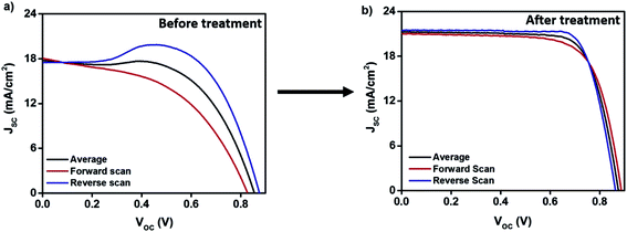 | ||
| Fig. 1 (a) J–V curves of the champion CPSC (b) J–V curves of the same CPSC after HTE treatment for a period of 115 hours. | ||
| Name | Scan | J SC (mA cm−2) | V OC (mV) | FF | η (%) | R CELL (Ω) |
|---|---|---|---|---|---|---|
| Fresh | Forward | 18.1 | 0.828 | 0.49 | 7.3 | 75.5 |
| Reverse | 17.5 | 0.875 | 0.72 | 11.1 | 50.4 | |
| Average | 17.8 | 0.851 | 0.60 | 9.2 | 62.9 | |
| HTE treated (115 h) | Forward | 21.0 | 0.887 | 0.71 | 13.3 | 28.2 |
| Reverse | 21.5 | 0.863 | 0.77 | 14.3 | 29.5 | |
| Average | 21.2 | 0.875 | 0.74 | 13.8 | 28.8 |
The detailed trends of these impressive changes in the photovoltaic parameters are also summarized in Fig. 2, where the fabricated batch (7 cells) was measured periodically up to 200 hours, after which slight signs of degradation appeared at the edges of some of the devices in this batch, indicating the extreme limits of exposure (Fig. 3a and b). Hence the HTE treatment was restricted to 115–120 hours for further batches of CPSCs fabricated for this study. Nevertheless, the overall photovoltaic performance was not compromised (η = 13.1% ± 0.2%) and no major physical changes were observed, which was further verified by measuring the reflectance of the fabricated CPSCs (Fig. 3a–c).
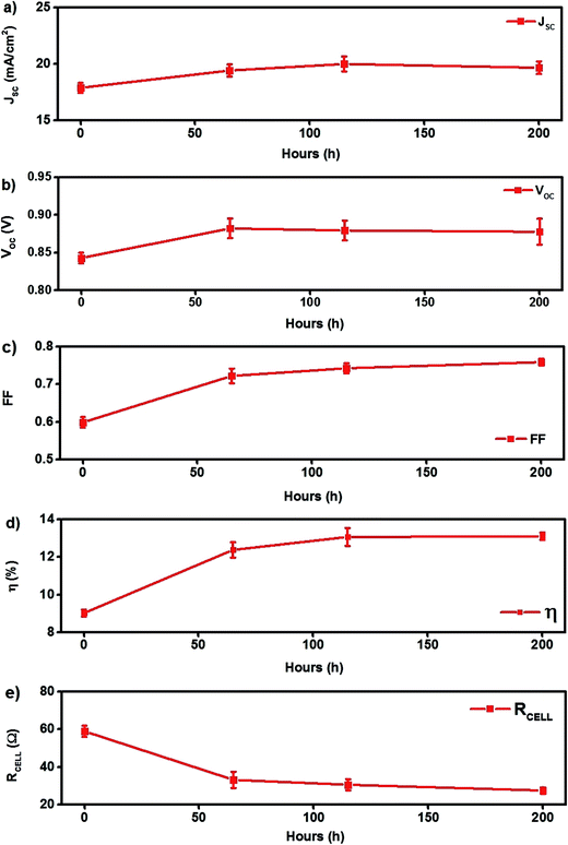 | ||
| Fig. 2 Photovoltaic parameters of a batch (7 cells) of CPSCs exposed in the environmental chamber for the HTE treatment. The values represent the average of forward- and reverse-scanned J–V curves (see also the ESI†). | ||
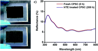 | ||
| Fig. 3 (a) Front and (b) back view and (c) initial and aged reflectance spectra of a HTE treated CPSC for a period of 200 h. | ||
More importantly, the repetitive J–V curves of some of these HTE treated CPSCs were also obtained by scanning them under full sunlight illumination to determine if the drastic improvements in their overall photovoltaic parameters was permanent or not. Fig. 4 presents ten consecutive J–V curves of a HTE treated CPSC which showed exceptionally high stability by exhibiting no change in the overall conversion efficiency (13%) with a minimal compensation in the JSC (1.5% increased) and VOC (only 0.5% decrement) values, which were stabilized after five scans (Fig. 4).
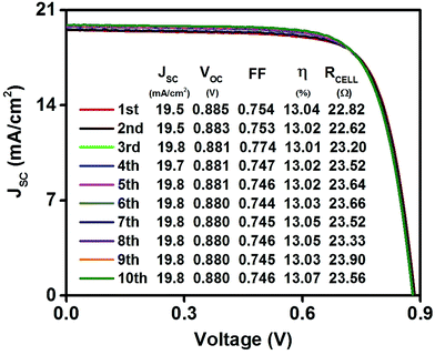 | ||
| Fig. 4 J–V curves obtained from 1–10 times scanning of a high performance HTE treated CPSC for a period of 115 hours. The values represent the average of forward- and reverse-scanned J–V curves. | ||
Motivated by these promising findings, we further investigated both the fresh and HTE exposed CPSC device structures via isolating key components, which directly influence their overall photovoltaic performance. In this regard, the carbon back contact electrode was first examined by the four-probe sheet resistance measurement method (see the ESI†) since it directly contributes to the open circuit voltage (VOC) and fill factor (FF), which were significantly improved during the HTE treatment. As expected, the sheet resistance (RSH = 8.5 ± 0.10 Ω Sq−1) of the HTE treated CPSCs was impressively reduced (by 13%) compared to that of the fresh CPSCs before exposing them to HTE treatment (Table 2), thus attesting to the improvements in the overall conductivity of the porous carbon electrode. We confidently state that these improvements are mainly attributed due to an increase in the interconnectivity of carbon nanoparticles through a possible crystal growth of the perovskites (after their precursor infiltration and heating at 50 °C), which may be enhanced within the porous stack during HTE treatment that consequently influenced the fill factor and open circuit voltage of the fabricated CPSCs (Fig. 2).
| Electrode | Sheet resistance (Ω Sq−1) | No of electrodes |
|---|---|---|
| Fresh carbon back electrode (without perovskite precursor infiltration) | 14.4 ± 0.1 | 3 |
| Fresh carbon back electrode after perovskite infiltration and crystallization at 50 °C | 9.8 ± 0.4 | 3 |
| Carbon back electrode after HTE treatment (115 h) | 8.5 ± 0.1 | 3 |
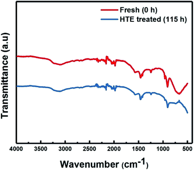
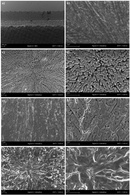
Therefore, the structure of the perovskite crystals within the CPSC stack was also examined via X-ray diffraction (XRD) measurements. Fig. 5a shows the XRD patterns of a CPSC collected at the initial state and up to 115 hours of HTE treatment which did not induce any growth of PbI2.24 During HTE treatment, the perovskite structure remained unchanged at the atomic level: the d spacing remained constant, indicating no release of stress or strain and the FWHM of the diffraction peaks varied only slightly. The perovskite crystal structure was also cross-checked from FTIR spectra (Fig. 6) which also remained almost unaltered during the aging process, suggesting that the HTE treatment did not have any effect on the perovskite chemical configuration. On the other hand, an increase in the integrated intensity of the strongest perovskite reflection at 14.1° (ref. 15 and 16) was observed, most likely due to a slight increase in crystallite sizes which supports the idea of reorganization of the crystallites within the porous matrix. Hence, the effect of the HTE on the morphology and appearance of the perovskite layer was correspondingly analysed at the edge of the carbon electrode of CPSCs by scanning electron microscopy (Fig. 7 a). The micrographs revealed a steady perovskite crystal growth (Fig. 7d, e and h) in the HTE-treated devices compared to the fresh ones (Fig. 7b) and consequently reduced the reduced overall porosity (Fig. 7g and h) which was well evident in the fresh devices (Fig. 7b–d) thus providing another evidence for crystallite growth within the porous stack of the fabricated devices.
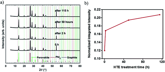 | ||
| Fig. 5 (a) XRD patterns of a CPSC obtained via periodical measurements from 0–115 hours (b) normalized integral peak intensity of the same CPSC monitored from 0–115 hours. | ||
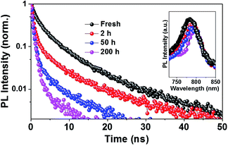
In addition to this, we also explored steady-state and time-resolved photoluminescence (PL, Fig. 8) to understand the influence of HTE on the emission characteristics of the perovskite layer. Upon exciting the perovskite samples at 450 nm, PL spectra corresponding to the band-to-band recombination appeared around 780 nm (inset; Fig. 8), in agreement with the intrinsic bandgap of CH3NH3PbI3.25 The injection of electrons from the conduction band (CB) of the perovskite into that of TiO2 was further investigated by probing the decay of emission using the time-correlated single photon counting (TCSPC) technique. Fig. 6 shows the time-resolved photoluminescence (TRPL) spectra acquired from various perovskite devices measured at λmax upon excitation at 408 nm from the FTO side. With increasing duration of HTE of the perovskite devices, PL quenching increased continuously, establishing that electron injection from the CB of the perovskite into that of TiO2 becomes relatively more efficient when devices are subjected to HTE.26 Probably, in addition to improving the crystallinity, HTE makes the interface between mesoporous TiO2 and the perovskite layer more favorable for electron injection, which eventually increases the JSC.
The evidence of the perovskite crystal growth under humidity was first reported by You et al. in one of the traditional thin film geometry based PSCs where the thermal annealing of the perovskite precursor film was performed under ambient air (humidity = 35% ± 5%).27 Similar enhancements (as presented here in this work) were also observed in their photovoltaic parameters, which include high FF (>80%) and high JSC (∼20 mA cm−2) values.27 Nevertheless, due to the thin stack (∼1 μm) in any type of combination for traditional PSCs (such as that presented in ref. 11), the devices do not survive in a highly humid environment over longer periods of time as due to its hygroscopic nature, the CH3NH3I rapidly decomposes within the perovskite crystals and affects the overall device performance.27 Contrary to this, the 12–14 times thicker and robust device architecture in the case of CPSCs makes it possible to expose the devices to much higher humidity for longer periods of time. We propose that the thick (10–12 μm) hydrophobic carbon electrode of CPSCs, during the HTE treatment, works as a ‘mesh’ i.e. strongly blocks the rapid intrusion of large water droplets which may be produced in this ‘thermo-humid’ environment and only allows the gaseous state of the moisture to first pass through it and then proceed through more dense mesoporous ZrO2 to assist the irreversible perovskite crystal growth both in the TiO2 scaffold as well as in the whole porous stack without changing its chemical structure.
Finally, the remaining task in this work was to test the long-term stability of the HTE-treated CPSCs. In this regard, one more batch (6 cells) of the HTE exposed CPSCs was subjected to full sun illumination at 40 °C. Fig. 9a–e present the results of the photovoltaic parameters of the subjected CPSCs for a period of 350 hours of this ongoing stability test which retained ∼92% of the average initial efficiency thus endorsing the high performance durability and calling for an opportunity to apply this interesting method also over large area carbon-based perovskite solar modules to further enhance their performance which is now crossing 10%.22,28 The initial slight decrease and increase in the FF and RCELL values, respectively, is an expected result due to the additional contacts (fabricated with copper tapes and silver paint and further protected with the slowly drying epoxy) that were slowly stabilized and consequently improved and retained the VOC and the conversion efficiencies respectively (see also the statistical data in the ESI†).
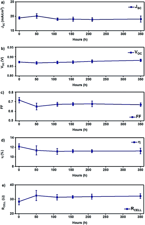 | ||
| Fig. 9 Stability data of a batch of CPSCs (6 cells) along with their standard deviations for a period of 350 hours. | ||
In recent CPSC developments, efforts have mostly been made to formulate new precursor solutions of perovskites by introducing new solvents and materials which have shown good performances.19,20 However, the importance of reducing the overall cell resistance of CPSCs has been hardly discussed22 and has not been highlighted before this report. Further improvements in reducing the cell resistance in future work may also be realized by fabricating more conductive carbon back electrodes (i.e. replacing large graphite particles with low cost and conductive multi-walled carbon nanotubes (MWCNTs) or single walled carbon nanotubes (SWCNTs)). An additional HTE treatment such as the one presented in this study should potentially influence the overall photovoltaic performance by decreasing further the sheet resistance of these highly conductive carbon back electrodes within the CPSC device configuration.
To sum up, we successfully demonstrated here humidity assisted thermal exposure (HTE) as a post-treatment scheme to obtain high performance and durable carbon-based printed perovskite solar cells. It was shown in this work that traditional heating (at 50 °C) after perovskite precursor infiltration into their highly porous stack is not enough to generate sufficient perovskite crystal growth and also does not effectively improve the interfaces of the porous stack of the CPSCs. The additional HTE treatment directly influences over the associated components in the stack and remarkably improves each photovoltaic parameter of the CPSCs which were further certified by several characterization schemes presented in this study. With HTE, the average initial efficiencies (9.0% ± 0.2%, calculated from forward and reverse scans of the J–V curves) of the fabricated devices were greatly improved to 13.1% ± 0.2% i.e. as high as 45% after exposing one batch of solar cells for a period of 200 hours (Fig. 2, see also the ESI†). The highest average efficiency obtained from the same batch from the reverse scanning of the fabricated CPSCs was 13.8% ± 0.4% with a CPSC attaining as high as 14.3% (Fig. 1 and Table 1) after 115 hours of exposure in an automated weather chamber. Moreover, the long-term photovoltaic performance of the HTE treated CPSCs has also not been compromised for greater than 350 hours under stressful conditions in the stability test. The results presented in this work are very encouraging for the adoption of HTE treatment as an additional step in the standard CPSC fabrication procedure to obtain high performance carbon-based perovskite solar cells with low hysteresis accompanied by high durability and reliable performance reproducibility.
Acknowledgements
This work was mainly financed through grant number 287641. Ghufran Hashmi gratefully acknowledges the Academy of Finland for the post-doctoral research fellowship and also pays special thanks to Solaronix for hosting his research mobility for the project “Cutting-Edge Third Generation Advanced Photovoltaic Devices”. Fruitful discussions with Professor Robin Ras and Dr Jukka Hassinen during this work are also acknowledged. The authors also acknowledge the provision of facilities and technical support by Aalto University at the OtaNano – Nanomicroscopy Center (Aalto-NMC).References
- S. S. Shin, E. J. Yeom, W. S. Yang, S. Hur, M. G. Kim, J. Im, J. Seo, J. H. Noh and S. I. Seok, Colloidally prepared La-doped BaSnO3 electrodes for efficient, photostable perovskite solar cells, Science, 2017, eaam6620 Search PubMed.
- Best Research Cell-Efficiencies, National Renewable Energy Laboratory (NREL), April 20 2016, https://www.nrel.gov/pv/assets/images/efficiency_chart.jpg Search PubMed.
- J. Gong, S. B. Darling and F. You, Energy Environ. Sci., 2015, 8, 1953–1968 CAS.
- Y. Han, S. Meyer, Y. Dkhissi, K. Weber, J. M. Pringle, U. Bach, L. Spiccia and Y. B. Cheng, Degradation observations of encapsulated planar CH3NH3PbI3 perovskite solar cells at high temperatures and humidity, J. Mater. Chem. A, 2015, 3, 8139–8147 CAS.
- http://www.chemborun.com/ .
- M. Cai, Y. Wu, H. Chen, X. Yang, Y. Qiang and L. Han, Cost-Performance Analysis of Perovskite Solar Modules, Adv. Sci., 2017, 4, 1600269 CrossRef PubMed.
- A. A. Asif, R. Singh and G. F. Alapatt, Technical and economic assessment of perovskite solar cells for large scale manufacturing, J. Renewable Sustainable Energy, 2015, 7, 1 Search PubMed.
- T. Leijtens, G. E. Eperon, S. Pathak, A. Abate, M. M. Lee and H. J. Snaith, Overcoming ultra-violet light instability of sensitized TiO2 with meso-superstructured organometal tri-halide perovskite solar cells, Nat. Commun., 2013, 4, 2885 Search PubMed.
- Q. Tai, P. You, H. Sang, Z. Liu, C. Hu, H. L. W. Chan and F. Yan, Efficient and stable perovskite solar cells prepared in ambient air irrespective of the humidity, Nat. Commun., 2016, 7, 1–8 Search PubMed.
- K. G. Lim, H. B. Kim, J. Jeong, H. Kim, J. Y. Kim and T. W. Lee, Boosting the Power Conversion Efficiency of Perovskite Solar Cells Using Self-Organized Polymeric Hole Extraction Layers with High Work Function, Adv. Mater., 2014, 26, 6461–6466 CrossRef CAS PubMed.
- Y. Bai, H. Yu, Z. Zhu, K. Jiang, T. Zhang, N. Zhao, S. Yang and H. Yan, High performance inverted structure perovskite solar cells based on a PCBM: polystyrene blend electron transport layer, J. Mater. Chem. A, 2015, 3, 9098–9102 CAS.
- A. Mei, X. Li, L. Liu, Z. Ku, T. Liu, Y. Rong, M. Xu, M. Hu, J. Chen, Y. Yang, M. Grätzel and H. Han, A hole-conductor-free, fully printable mesoscopic perovskite solar cell with high stability, Science, 2014, 345, 295–298 CrossRef CAS PubMed.
- G. Li, T. Zhang and Y. Zhao, Hydrochloric acid accelerated formation of planar CH3NH3PbI3 perovskite with high humidity tolerance, J. Mater. Chem. A, 2015, 3, 19674–19678 CAS.
- L. Liu, A. Mei, T. Liu, P. Jiang, Y. Sheng, L. Zhang and H. Han, Fully printable mesoscopic perovskite solar cells with organic silane self-assembled monolayer, J. Am. Chem. Soc., 2015, 137, 1790 CrossRef CAS PubMed.
- S. G. Hashmi, D. Martineau, X. Li, M. Ozkan, A. Tiihonen, M. I. Dar, T. Sarikka, S. M. Zakeeruddin, J. Paltakari, P. D. Lund and M. Grätzel, Air processed inkjet infiltrated carbon based printed perovskite solar cells with high stability and reproducibility, Adv. Mater. Technol., 2016, 1600183, 1–6 Search PubMed.
- S. G. Hashmi, A. Tiihonen, D. Martineau, M. Ozkan, P. Vivo, K. Kaunisto, V. Ulla, S. M. Zakeeruddin and M. Grätzel, Long term stability of air processed inkjet infiltrated carbon-based printed perovskite solar cells in ultra-violet light soaking, J. Mater. Chem. A, 2017, 5, 4797–4802 CAS.
- J. Chen, Y. Rong, A. Mei, Y. Xiong, T. Liu, Y. Sheng, P. Jiang, L. Hong, Y. Guan, X. Zhu, X. Hou, M. Duan, J. Zhao, X. Li and H. Han, Hole-Conductor-Free Fully Printable Mesoscopic Solar Cell with Mixed-Anion Perovskite CH3NH3PbI(3 − x)(BF4)x, Adv. Energy Mater., 2015, 1502009, 1 Search PubMed.
- C. Y. Chan, Y. Wang, G. W. Wu and E. W. G. Diau, Solvent-extraction crystal growth for highly efficient carbon-based mesoscopic perovskite solar cells free of hole conductors, J. Mater. Chem. A, 2016, 4, 3872–3878 CAS.
- C. M. Tsai, G. W. Wu, S. Narra, H. M. Chang, N. Mohanta, H. P. Wu, C. L. Wang and E. W. G. Diau, Control of preferred orientation with slow crystallization for carbon-based mesoscopic perovskite solar cells attaining efficiency 15%, J. Mater. Chem. A, 2017, 5, 739–747 CAS.
- H. Zhang, H. Wang, S. T. Williams, D. Xiong, W. Zhang, C.-C. Chueh, W. Chen and A. K.-Y. Jen, SrCl2 Derived Perovskite Facilitating a High Efficiency of 16% in Hole Conductor-Free Fully Printable Mesoscopic Perovskite Solar Cells, Adv. Mater., 2017, 1606608 CrossRef PubMed.
- H. Chen and S. Yang, Carbon-Based Perovskite Solar Cells without Hole Transport Materials: The Front Runner to the Market?, Adv. Mater., 2017, 1603994 CrossRef PubMed.
- Y. Hu, S. Si, A. Mei, Y. Rong, H. Liu, X. Li and H. Han, Stable Large-Area (10 × 10 cm2) Printable Mesoscopic Perovskite Module Exceeding 10% Efficiency, Sol. RRL, 2017, 1, 1600019 CrossRef.
- https://www.arctest.fi/en/products/environmental-testing/environmental-test-chambers .
- M. I. Dar, M. Abdi-Jalebi, N. Arora, M. Grätzel and M. K. Nazeeruddin, Adv. Energy Mater., 2016, 6, 1501358 CrossRef.
- M. I. Dar, G. Jacopin, S. Meloni, A. Mattoni, N. Arora, A. Boziki, S. M. Zakeeruddin, U. Rothlisberger and M. Grätzel, Sci. Adv., 2016, 2, e1601156 Search PubMed.
- N. Arora, M. I. Dar, M. Abdi-Jalebi, F. Giordano, N. Pellet, G. Jacopin, R. H. Friend, S. M. Zakeeruddin and M. Grätzel, Nano Lett., 2016, 16, 7155–7162 CrossRef CAS PubMed.
- J. You, Y. M. Yang, Z. Hong, T. B. Song, L. Meng, Y. Liu, C. Jiang, H. Zhou, W. H. Chang, G. Li and Y. Yang, Moisture assisted perovskite film growth for high performance solar cells, Appl. Phys. Lett., 2014, 105, 183902 CrossRef.
- A. Priyadarshi, L. J. Haur, P. Murray, D. Fu, S. Kulkarni, G. Xing, T. C. Sum, N. Mathews and S. G. Mhaisalkar, A large area (70 cm2) monolithic perovskite solar module with a high efficiency and stability, Energy Environ. Sci., 2016, 9, 3687–3692 CAS.
Footnote |
| † Electronic supplementary information (ESI) available. See DOI: 10.1039/c7ta04132b |
| This journal is © The Royal Society of Chemistry 2017 |

