
 Open Access Article
 This Open Access Article is licensed under a
 Creative Commons Attribution 3.0 Unported Licence
Fabrication of nanoscale NiO/Ni heterostructures as electrocatalysts for efficient methanol oxidation†
Juan
Wang
a,
Detre
Teschner
b,
Yuanying
Yao
a,
Xing
Huang
 *b,
Marc
Willinger
b,
Lidong
Shao
*a and
Robert
Schlögl
b
*b,
Marc
Willinger
b,
Lidong
Shao
*a and
Robert
Schlögl
b
aShanghai Key Laboratory of Materials Protection and Advanced Materials in Electric Power, Shanghai University of Electric Power, Shanghai 200090, China. E-mail: lidong.shao@shiep.edu.cn
bDepartment of Inorganic Chemistry, Fritz-Haber Institute of the Max Planck Society, Faradayweg 4-6, 14195 Berlin, Germany. E-mail: xinghuang@fhi-berlin.mpg.de
First published on 3rd May 2017
Abstract
Nanoscale NiO/Ni heterostructures on oxygen-functionalized carbon nanotubes with low Ni loading (3–4 wt%) are fabricated by delicate thermal-annealing treatments, which are designed according to the temperature-programmed thermal analysis. Activity and stability tests demonstrate that NiO/Ni heterostructures with a stable Ni core inside an oxyhydroxide shell (in solution) exhibit enhanced stability and catalytic activity for methanol oxidation.
Introduction
Controlled synthesis of catalysts with well-defined sizes, shapes, crystal facets, structures, and compositions could potentially lead to enhanced catalytic activities, which remain a desirable yet challenging goal. Nanostructured materials often show extraordinary properties and are considered highly promising for applications in electrocatalysis. Core–shell nanoparticles (NPs) are a class of nanostructured materials that involve deliberate tailoring of the nanostructure through changes in the core–shell construction. Such changes can substantially enhance the catalytic activity.1,2 Recently, the development of metal-based core–shell NPs for electrochemical catalysis has drawn considerable interest. Some studies have shown that the electrocatalytic activity and stability of a core–shell structure can be improved by electronic (alloying) effects and structure-induced strain (geometry) effects.3 Various methods have been reported for the synthesis of NPs with core–shell structures, including galvanic replacement,4 surface dealloying,5 and seed-mediated growth of the shell material, in which the initial nucleation is controlled and growth occurs around core NPs.6Ni and NiO nanomaterials are important subjects of investigation for electrocatalytic oxidation of small molecules, such as aliphatic short chain alcohols.7–10 Knez and co-workers synthesized NiO NPs with good crystallinity and uniform dispersion on pristine carbon nanotubes (CNTs) by atomic layer deposition, and determined the size dependency and mass electrochemical activity of the NiO redox reaction for methanol oxidation.9 Ni–P–O compounds with astrocyte-network morphologies that provide large surface areas were synthesized for methanol oxidation, and the unique microstructures and compositions of these compounds were found to contribute to the excellent catalytic activity.10 Guo and co-workers reported CNT-Ni/SiC composites with three-dimensional hierarchical nanostructures for methanol oxidation, which exhibited good electrocatalytic activity and stability.11 However, these methods require complicated procedures and are often limited to bench-scale experiments.
Surface characterization of these catalysts has revealed that, under exposure to air or aqueous solution, a Ni hydroxide and oxide layer quickly forms on the Ni surface. Thus, most reported Ni NP catalysts inevitably include a thin oxide layer (or hydroxide layer in solution).12 It is challenging to fabricate Ni-based heterostructures with controllable compositions using a scalable synthesis approach.
In the present work, pure-phase Ni, pure-phase hollow-structured NiO, and NiO/Ni core–shell structures on oxygen-functionalized CNTs (OCNTs) were prepared through delicate temperature-controlled reduction synthesis procedures (details are described in the ESI†). Further, methanol was selected as a target small molecule to investigate the electrocatalytic activities of these materials in alkaline solution.
Experimental section
Preparation of catalysts
An oxidative pretreatment in boiling nitric is conducted to introduce oxygenated functional groups onto the surface of the carbon nanotubes. OCNTs were obtained by oxidation of CNTs with HNO3. Ni(NO3)2·6H2O (10.32 mg) and OCNTs (50 mg) were dispersed in ethanol and the precursor coordinated to functional groups which act as anchoring sites on OCNTs. After ultrasonication for 20 min, the functionalized CNTs readily interact with the metal precursors, bonds between nickel precursor and oxygen functionalized CNTs formed. After that, the sample was dried under vacuum at 60 °C. Subsequently, the sample was annealed in a tube furnace at 310 °C for 2 h under a He atmosphere to obtain sample NiO310. Then, sample NiO310 was annealed at 400 °C for 2 h under a He/H2 atmosphere. The furnace was then slowly cooled to room temperature to obtain the NiO/Ni@CNT catalyst. The Ni@CNT catalyst was synthesized by annealing sample NiO310 at 500 °C for 2 h under a He/H2 atmosphere. The NiO@CNT catalyst was synthesized by thermal decomposition of the Ni@CNT catalyst at 400 °C for 30 min under air.Characterization
An aberration-corrected JEOL JEM-ARM200CF transmission electron microscope (TEM) was employed to investigate the structural and chemical properties in scanning TEM (STEM) mode. A Bruker DAVINCI D8 ADVANCE diffractometer with Cu Kα radiation (λ = 0.15406 nm) was used for X-ray diffraction (XRD) characterization. X-ray photoelectron spectroscopy (XPS) characterization was conducted using a Thermo ESCALAB 250 spectrometer with an Al Kα radiation source (passing energy: 30 eV). All binding energies were calibrated using the C1s hydrocarbon peak at 284.60 eV. Inductively coupled plasma optical emission spectrometry (ICP-OES, PerkinElmer Optima 8000) was used to determine the Ni content in the samples. For temperature-programmed reduction of H2 (H2-TPR) tests (Chemisorption Analyzer AutoChem II), 50 mg of sample was put in a quartz tubular reactor with a temperature sensor, purged with high-purity He at 400 °C for 1 h, and then cooled to room temperature. Subsequently, 10% H2/He was introduced at a flow rate of 50 mL min−1 and the reactor was heated to 800 °C at a rate of 10 °C min−1. For temperature programmed desorption of CO2 (CO2-TPD) tests (Chemisorption Analyzer AutoChem II), 50 mg of sample was placed in a quartz tubular reactor with a temperature sensor. Before the adsorption of CO2, a blank TPD test was conducted from 25 to 600 °C to ensure no desorption. Subsequently, the reactor was purged with CO2 with He flow for 0.5 h, then heated to 800 °C at a rate of 10 °C min−1, and maintained at this temperature for 2 h for the CO2-TPD test. H2 pulse chemisorption measurements of catalyst samples were applied at 50 °C to determine the influence of reduction conditions on metal dispersion. Prior to H2 pulse chemisorption measurements, the catalysts were activated in a H2 (10 vol%)/Ar flow (50 mL min−1) at a heating rate of 10 °C min−1 up to the required reduction temperature 400 °C, at which the samples were held for 1 h. The pre-reduced samples were then purged in flowing Ar to remove the residual H2 and cooled to 50 °C. Pulses of H2 (10 vol%)/Ar were after that injected into a stream of Ar flowing through the pre-reduced sample bed. The dispersion of nickel based on the hemispherical model has been calculated from the volume of adsorbed hydrogen and Ni content of the sample assuming that adsorption stoichiometry of the irreversibly adsorbed hydrogen atom per surface nickel atom is unity.13,14 And the equation is as follows:| % dispersion = [number of Ni atoms on surface/number of Ni atoms in sample] × 100 |
Electrochemical measurements
A potentiostat (SP-300, BioLogic Science Instruments) was used to investigate the electrochemical properties of the catalysts. All electrochemical measurements were conducted in a three-electrode cell with Pt wire as the counter electrode, a glassy carbon (GC) disk (3 mm diameter) as the working electrode, and Hg/HgO as the reference electrode, and the electrolyte was 1 M KOH. Prior to each experiment, the electrolyte solution was purged with high-purity N2 gas for 20 min. All solutions were prepared with Milli-Q water. The working electrode was prepared by dispersing 2 mg of the as-prepared catalyst in a mixture of 200 μL of deionized water, 800 μL of ethanol, and 120 μL of 5 wt% Nafion solution. Then, 5.6 μL of the mixture was placed on a GC disk electrode, which was then dried gently in air. All the electrochemical tests were conducted at temperature of 25 °C.Results and discussion
Composition and structural characterization
The structural and surface chemical properties of the samples were examined using TEM. Fig. 1a shows an annular dark-field STEM (ADF-STEM) image of NiO NPs with compact hollow shells, whereas thin shells are observed for the NiO/Ni core–shell particles (Fig. 1b). Chemical mapping (Fig. 1e, h, and k) reveals the distribution of elemental O in the shells and Ni in the cores of NiO/Ni@CNTs. The sporadic and uneven distribution of O in Ni@CNTs (Fig. 1f and l) suggested that most O was derived from surface-adsorbed O-containing species, which may cause slight surface oxidation. The particle sizes of the catalysts are indicated in the STEM images, and the corresponding size distribution histograms are shown in Fig. 2a–c. For the NiO@CNT catalyst, the particle size ranged from 1.5–8.0 nm, with an average particle size of 4.10 nm (Fig. 2a). For the NiO/Ni@CNT catalyst (Fig. 2b), the particle sizes mainly ranged from 3 to 15 nm, with an average size of 7.93 nm. Relative to the size of the NiO/Ni@CNT catalyst, the particle size of Ni@CNTs was larger, ranging from 2 to 20 nm with an average size of 9.17 nm (Fig. 2c). HRTEM images of the catalysts are shown in Fig. 2e and f. NiO is observed to have finger lattices of 0.24 and 0.2 nm, which correspond to the (111) and (200) planes, respectively, whereas Ni has a finger lattice of 0.18 nm, which corresponds to the (200) plane.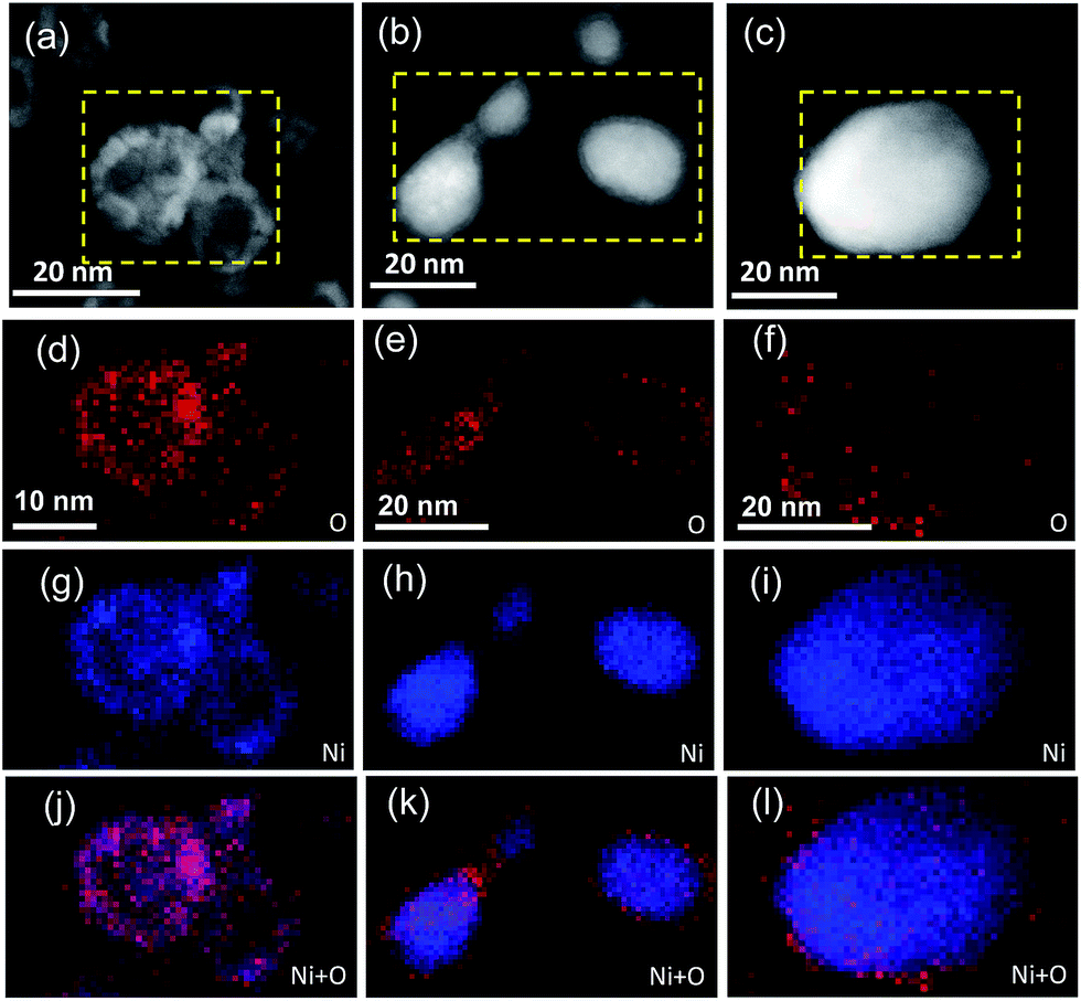 | ||
| Fig. 1 ADF-STEM images of NiO@CNTs (a), NiO/Ni@CNTs (b), and Ni@CNTs (c). Chemical mapping of the NPs in NiO@CNTs (d, g, and j), NiO/Ni@CNTs (e, h, and k), and Ni@CNTs (f, i, and l). | ||
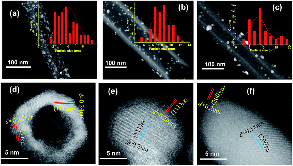 | ||
| Fig. 2 STEM images and the size distribution histograms of NiO@CNTs (a), NiO/Ni@CNTs (b), and Ni@CNTs (c). HRTEM images of NiO hollow-shell (d), core–shell NiO/Ni (e), and Ni particles (f). | ||
In the X-ray diffraction (XRD) patterns of the catalysts (Fig. 3a), the diffraction peaks at 44.5° and 43.3° correspond to the (111) plane of Ni (JCPDS, no. 04-0850) and the (200) plane of NiO (JCPDS, no. 47-1049). The broad peak at 26.3° is associated with the (002) plane of the graphite-like structure of multiwall CNTs.15 It is found that the full width at half maxima (FWHM) of the main XRD peaks becomes broader from Ni@CNTs to NiO/Ni@CNTs and NiO@CNTs, which indicates that the particle sizes and particle size distributions of the samples are different. Using Scherrer's formula, the average sizes of the crystallites were calculated to be 4.0, 8.0, and 9.4 nm from the diffraction peak for the (200) plane of NiO for the NiO@CNT catalyst and the peaks for the (111) plane of Ni for the NiO/Ni@CNT and Ni@CNT catalysts, respectively. The particle sizes calculated from the XRD results were similar to those from the TEM characterization. XRD pattern of OCNTs was shown in Fig. S1.†
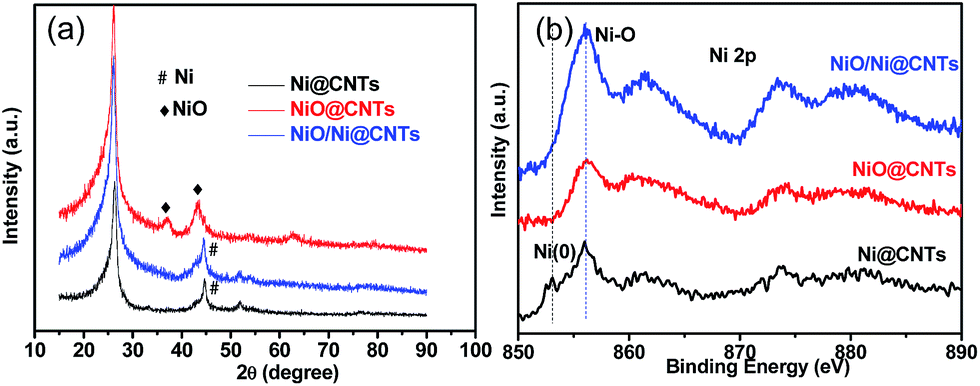 | ||
| Fig. 3 XRD patterns (a) and XPS patterns (b) of NiO@CNTs, NiO/Ni@CNTs, and Ni@CNTs. | ||
X-ray photoelectron spectroscopy (XPS) was applied to investigate the surface chemical states of the catalysts. The as-prepared catalysts exhibited mostly oxidized Ni species (856.0 eV), with a peak from Ni0 at around 853.0 eV for the Ni@CNTs (Fig. 3b). The C1s and O1s profiles of NiO/Ni@CNTs are displayed in Fig. S2 and S3,† respectively. There are six contribution to the C1s core level of the catalyst: C1 (284.6 eV, C–C), C2 (285.2 eV, C–H), C3 (286.8 eV, C![[double bond, length as m-dash]](https://www.rsc.org/images/entities/char_e001.gif) O), C4 (289.1 eV, O–CO), C5 (291.0 eV, and a π–π* shake-up feature).16 There are four contribution to the O1s: O1 (529.6 eV, O–Ni bond arising from NiO).17–19 O2 (531.1 ± 0.3 eV, CO groups), O3 (532.3 ± 0.3 eV, carbonyl oxygen atoms in esters, amides, anhydrides, and oxygen atoms in hydroxyl groups or ethers), and O4 (533.7 ± 0.3 eV, C–OH and/or C–O–C groups).20–22
O), C4 (289.1 eV, O–CO), C5 (291.0 eV, and a π–π* shake-up feature).16 There are four contribution to the O1s: O1 (529.6 eV, O–Ni bond arising from NiO).17–19 O2 (531.1 ± 0.3 eV, CO groups), O3 (532.3 ± 0.3 eV, carbonyl oxygen atoms in esters, amides, anhydrides, and oxygen atoms in hydroxyl groups or ethers), and O4 (533.7 ± 0.3 eV, C–OH and/or C–O–C groups).20–22
H2-TPR and CO2-TPD analyses
To design thermal treatment parameters for scalable synthesis of catalysts and obtain a better understanding of the relationship between electrocatalytic performance and surface chemical properties, H2-TPR and CO2-TPD tests were conducted. The first peaks (230–350 °C) in H2-TPR profiles (Fig. S4a†) are all attributed to the reduction of Ni2+ species.23 According to the H2-TPR profiles for different nickel species, the synthesis procedures for catalysts are as follows: firstly, nickel precursor was decomposed in a tube furnace at 310 °C under He atmosphere to obtain sample NiO310, but considering the decomposition condition for obtain NiO310 sample might be not sufficient to obtain complete NiO/Ni core–shell structure, thus, followed by a second step of calcination at 400 °C under He/H2 atmosphere for further reduction to get NiO/Ni@CNTs. Less NiO species of NiO/Ni@CNTs than that of NiO310 was also proved by the smaller H2-TPR peak of the former one. Furthermore, under the reduction temperature of 400 °C (He/H2), the NiO is not fully reduced to obtain pure Ni, thus, the reduction temperature of 500 °C (He/H2) is used following the first step to obtain Ni@CNTs. And the second peaks above 500 °C in H2-TPR profiles are arising from gasification of CNTs to methane via their reaction with H2 and reduction of surface functional groups on CNTs may also contributed to the H2 consumption.24,25 The physicochemical properties of the catalysts are shown in Table S1.† CO2-TPD tests were performed to determine the basicity of the catalysts, and the results are shown in Fig. S4b.† The peaks of OCNTs are associated with the decomposition of carboxylic anhydrides and lactones.26 The temperature desorption peaks around 460 °C correspond to the formation of HCO3− or CO32−, which cause basicity and are related to the formation of active oxyhydroxide phases during our electrocatalytic reactions. This result indicated that the NiO/Ni@CNT catalyst possessed more basic sites than the NiO@CNT and Ni@CNT catalysts.27Electrochemical properties of catalysts
The catalysts exhibited typical cyclic voltammetry (CV) behavior in 1 M KOH (Fig. S5a–c†). Redox peaks were observed between 300 and 500 mV, which correspond to the Ni2+/Ni3+ redox couple.13 A linear relationship between the anodic peak current (Ipa) and the square root of the scan rate (ν1/2) is evident in Fig. 4a. The slopes of these plots for NiO/Ni@CNTs, NiO@CNTs, and Ni@CNTs are 0.00830, 0.00598, and 0.00204, respectively. The larger slope for NiO/Ni@CNTs indicates that OH− has relatively better diffusion properties;28 thus, more electroactive species, such as NiOOH, can form on the surface of NiO/Ni@CNTs than on the surfaces of the other catalysts. To evaluate the effect of the core–shell heterostructure on catalyst activity, CV measurements of methanol oxidation were carried out (Fig. 4b). The electrocatalytic activity of NiOOH toward methanol is considered to arise from the unpaired d-electrons or empty d-orbitals associated with NiOOH, which are available for bond formation with absorbed species.29,30 The electro-oxidation mechanism of methanol over NiO is shown below:| NiO + OH− → NiOOH + e− | (1) |
| Ni(OH)2 + OH− → NiOOH + H2O + e− | (2) |
| OH− + 4NiOOH + CH3OH → 4Ni(OH)2 + HCOO− | (3) |
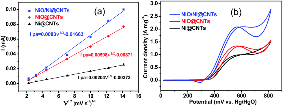 | ||
| Fig. 4 Linear relationship between the anodic peak current of cyclic voltammograms in 1.0 M KOH (Ipa) and the square root of the scan rate (ν1/2) for catalysts (a). Cyclic voltammograms of the catalysts in 1.0 M KOH + 1.0 M methanol (b). Scan rate: 50 mV s−1. | ||
Before the electrocatalytic activity tests, all catalysts were conditioned by potential cycling over 200 cycles at a scan rate of 50 mV s−1 in 1 M KOH. This procedure was used to enrich hydroxides and oxyhydroxides on the surface of the catalyst, which results in thickening of the electrocatalytic layers. The onset potential of NiO/Ni@CNTs was 324 mV vs. Hg/HgO, representing a negative shift of approximately 35 mV compared with those of NiO@CNTs and Ni@CNTs. Thus, the core–shell NiO/Ni@CNT heterostructure is kinetically more effective for methanol oxidation.11,31,32 In addition, the high mass-normalized activity at the peak potential near 580 mV (2094 mA mg−1) observed for NiO/Ni@CNTs was approximately 1.58 and 2.17 times those of NiO@CNTs (1328 mA mg−1) and Ni@CNTs (966 mA mg−1), respectively. A comparison of the activities of the catalysts in this study with those of previously reported Ni-based catalysts is shown in Table S2.† As the surface-active Ni species were the main contributor to the electrocatalytic activity, the activity toward methanol oxidation was also normalized to the surface Ni content. As shown in Fig. S6,† the normalized activity of NiO/Ni@CNTs is still higher than those of NiO@CNTs and Ni@CNTs. After the pretreatment of the catalysts in KOH, both NiO/Ni and Ni form a stable Ni core with an oxyhydroxide shell. This could be the reason why the NiO@CNT catalyst showed activity inferior to that of the NiO/Ni@CNT catalyst, despite the smaller particle size, higher dispersion, and higher surface content of NiO@CNT. This phenomenon was confirmed by subsequent multicycling stability tests. CV results for the catalysts for up to 300 cycles are shown in Fig. 5a, and the corresponding changes in peak current density are shown in Fig. 5b. It was noticed that a small redox peak corresponding to Ni(OH)2/NiOOH redox reaction for NiO/Ni@CNTs in the first few cycles CVs can be observed, however, this redox peaks are not obvious for both Ni@CNTs and NiO@CNTs, the easier formation of Ni(OH)2/NiOOH might contribute to the higher electrocatalytic activity (Fig. S7†). After 200 cycles, changes in the activities of NiO@CNTs and Ni@CNTs were evident; in particular, the catalytic activity of NiO@CNTs showed a significant decrease, whereas that of NiO/Ni@CNTs remained stable. When using NiO/Ni@CNTs for the methanol oxidation reaction, no obvious change in the oxidation current was observed as the scan rate was increased (Fig. S8a†), which indicates that methanol oxidation is not controlled by methanol diffusion. In addition, the current for methanol oxidation on NiO/Ni@CNTs did not increase when the methanol concentration exceeded 0.9 M (Fig. S8b†). Therefore, charge transfer plays an important role in the catalytic activity of the NiO/Ni@CNT heterostructures.11 This observation is in agreement with a study on the electrochemical properties of hierarchical CNT-Ni/SiC nanostructures.13 Chronoamperometric (CA) curves at 580 mV and the corresponding current densities at 1000, 1500, and 2000 s are shown in Fig. 5c and d. For NiO@CNTs, the current density evidently decreased from 1000 to 2000 s, whereas those of both the NiO/Ni@CNT and Ni@CNT samples remained stable. The NiO/Ni@CNT sample exhibited a much higher current density over time. Thus, the CA test demonstrates that the core–shell structure, with a stable Ni core and a Ni oxyhydroxide shell (in solution), is crucial for achieving electrocatalytic stability and activity for methanol oxidation.
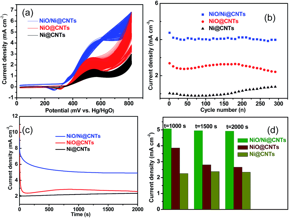 | ||
| Fig. 5 Multi-cycling stability tests (a) and corresponding changes in peak current density with cycle number (b) for the catalysts. Chronoamperometric curves at 580 mV (c) and the corresponding current densities at 1000, 1500, and 2000 s (d) for the catalysts. | ||
In the current work, the O-containing surface functionalities identified by XPS gave rise to an anchoring effect toward salt precursors. The applied temperature and treatment time affected the morphology and crystallinity of the nanocrystals. During the synthesis, the reduction of Ni precursors to form larger aggregates via Ostwald ripening was hindered by metal ions coordinated to the functional groups.
Hydrolysis was applied to crystallize the precursors nucleated on the oxidized carbon supports and to form interactions between the Ni species and the O-containing functionalities on the CNT surface. As a result, heterostructures could be formed on the Ni cores with a thin oxidized layer on the surface by tuning the calcination conditions. Further calcination of the Ni@CNT sample in air led to complete oxidation and transformation of the Ni NPs into NiO hollow-shell structurally modified CNTs. The transformation that occurred and the hollow shells of NiO remaining on the CNTs further confirm the role of the functionalized CNT surfaces in tuning the structures and morphologies of the catalysts during synthesis.
Conclusions
In summary, heterostructures consisting of Ni cores partially encapsulated within surface-oxidized layers of NiO were synthesized as electroactive catalysts with low Ni loadings. During deliberate thermal annealing treatments, carbon supports with O-containing functionalities were applied as substrates to tune the nanoscale morphologies of the obtained NiO/Ni heterostructures and NiO hollow-shell structures. Nanoscale pure-metallic and hollow-structured oxidative phases were used as reference catalysts for comparison to investigate the electrocatalytic activity for methanol oxidation. The design and scalable fabrication of such nickel-based catalysts may contribute to the exploration of more efficient heterostructure-induced activity effects for electrocatalysis.Acknowledgements
This work was supported by the Science and Technology Commission of Shanghai Municipality (No. 14DZ2261000). Open Access funding provided by the Max Planck Society.References
- J. H. Zeng, J. Yang, J. Y. Lee and W. J. Zhou, J. Phys. Chem. B, 2006, 110, 24606–24611 CrossRef CAS PubMed.
- K. Mikkelsen, B. Cassidy, N. Hofstertter, L. Bergquist, A. Taylor and D. A. Rider, Chem. Mater., 2014, 26, 6928–6940 CrossRef CAS.
- S. J. Guo, S. Zheng and S. H. Sun, Angew. Chem., Int. Ed., 2014, 52, 8526–8544 CrossRef PubMed.
- K. Sasaki, H. Naohara, Y. Cai, Y. M. Choi, P. Liu, M. B. Vukmirovic, J. X. Wang and R. R. Adzic, Angew. Chem., Int. Ed., 2010, 122, 8784–8789 CrossRef.
- P. Strasser, S. Koh, T. Anniyev, J. Greeley, K. More, C. F. Yu, Z. C. Liu, S. Kaya, D. Nordlund, H. Ogasawara, M. F. Toney and A. Nilsson, Nat. Chem., 2010, 2, 454–460 CrossRef CAS PubMed.
- V. Mazumder, M. F. Chi, K. L. More and S. H. Sun, J. Am. Chem. Soc., 2010, 132, 7848–7849 CrossRef CAS PubMed.
- Y. Mu, D. Jia, Y. He, Y. Miao and H. L. Wu, Biosens. Bioelectron., 2011, 26, 2948–2952 CrossRef CAS PubMed.
- H. Tian, M. Jia, M. Zhang and J. Hu, Electrochim. Acta, 2013, 96, 285–290 CrossRef CAS.
- X. L. Tong, Y. Qin, X. Y. Guo, O. Moutanabbir, X. Y. Ao, E. Pippel, L. B. Zhang and M. Knez, Small, 2012, 8, 3390–3395 CrossRef CAS PubMed.
- Y. Y. Tong, C. C. Gu, J. L. Zhang, M. L. Huang, H. Tang, X. L. Wang and P. J. Tu, J. Mater. Chem. A, 2015, 3, 4669–4678 CAS.
- S. Xie, X. L. Tong, G. Q. Jin, Y. Qin and X. Y. Guo, J. Mater. Chem. A, 2013, 1, 2104–2109 CAS.
- S. L. Medway, C. A. Lucas, A. Kowal, R. J. Nichols and D. Johnson, J. Electroanal. Chem., 2006, 587, 172–181 CrossRef CAS.
- A. Pintar and J. Batista, Appl. Catal., B, 2006, 63, 150–159 CrossRef CAS.
- G. Jacobs, T. Das, Y. Zhang, J. Li, G. Racoillet and B. H. Davis, Appl. Catal., A, 2002, 233, 263–281 CrossRef CAS.
- Y. C. Zhao, X. L. Yang, J. N. Tian, F. Y. Wang and L. Zhan, Int. J. Hydrogen Energy, 2010, 35, 3249–3257 CrossRef CAS.
- H. J. Wang, A. L. Zhou, F. Peng, H. Yu and J. Yang, J. Colloid Interface Sci., 2007, 316, 277–283 CrossRef CAS PubMed.
- M. Oku, H. Tokuda and K. Hirokawa, J. Electron Spectrosc. Relat. Phenom., 1991, 53, 201–211 CrossRef CAS.
- A. R. González-Elipe, R. Alvarez, J. P. Holgado, J. P. Espinos, G. Munuera and J. M. Sanz, Appl. Surf. Sci., 1991, 51, 19–26 CrossRef.
- P. H. Bolta, E. T. Grotenhuis, J. W. Geus and F. H. P. M. T. Habraken, Surf. Sci., 1995, 329, 227–240 CrossRef.
- C. Fettkenhauer, X. C. Wang, K. Kailasam, M. Antonietti and D. Dontsova, J. Mater. Chem. A, 2015, 3, 21227–21232 CAS.
- W. H. Zhang, S. C. Lin, C. M. Wang, J. Hu, C. Li, Z. X. Zhuang, Y. L. Zhou, R. A. Mathies and C. Y. Yang, Lab Chip, 2009, 9, 3088–3094 RSC.
- S. D. Gardner, C. S. K. Singamsetty, G. L. Booth, G. He and C. U. Pittman, Carbon, 1995, 33, 587–595 CrossRef CAS.
- H. X. Yang, S. Q. Song, R. C. Rao, X. Z. Wang, Q. Yu and A. M. Zhang, J. Mol. Catal. A: Chem., 2010, 323, 33–39 CrossRef CAS.
- S. Gharegozloo, A. Ataie, H. Abdizadeh, E. Mostafavi, M. J. Parnianb and A. A. Khodadadi, RSC Adv., 2016, 6(52), 47072–47082 RSC.
- K. Keyvanloo, A. Mohamadalizadeh and J. Towfighi, Appl. Catal., A, 2012, 417–418, 53–58 CrossRef CAS.
- S. Kundu, Y. M. Wang, W. Xia and M. Muhler, J. Phys. Chem. C, 2008, 112, 16869–16878 CAS.
- J. Wang, Z. Z. Wei, Y. T. Gong, S. P. Wang, D. F. Su, C. L. Han, H. R. Li and Y. Wang, Chem. Commun., 2015, 51, 12859–12862 RSC.
- M. S. Kim, T. S. Hwang and K. B. Kim, J. Electrochem. Soc., 1997, 144, 1537–1543 CrossRef CAS.
- M. Vidotti, C. D. Cerri, R. F. Carvalhal, J. C. Dias, R. K. Mendes, S. I. Córdoba de Torresi and L. T. Kubota, J. Electroanal. Chem., 2009, 636, 18–23 CrossRef CAS.
- L. A. Hutton, M. Vidotti, A. N. Patel, M. E. Newton, P. R. Unwin and J. V. Macpherson, J. Phys. Chem. C, 2010, 115, 1649–1658 Search PubMed.
- L. R. Zhang, J. Zhao, M. Li, H. T. Ni, J. L. Zhang, X. M. Feng, Y. W. Ma, Q. L. Fan, X. Z. Wang, Z. Hu and W. Huang, New J. Chem., 2012, 36, 1108–1113 RSC.
- Q. F. Yi, W. Huang, J. J. Zhang, X. P. Liu and L. Li, Catal. Commun., 2008, 9, 2053–2058 CrossRef CAS.
Footnote |
| † Electronic supplementary information (ESI) available: XPS C1s and O1s profiles, H2-TPR and CO2-TPD profiles, CVs of catalysts normalized to the surface Ni content, current response of methanol oxidation with different scan rates and different methanol concentrations, and tables comparing structural parameters and activities. See DOI: 10.1039/c7ta01982c |
| This journal is © The Royal Society of Chemistry 2017 |