 Open Access Article
Selective blocking of grain boundary defects in high-flux zeolite membranes by coking†
D.
Korelskiy
 *,
P.
Ye
,
M. S.
Nabavi
and
J.
Hedlund
Chemical Technology, Luleå University of Technology, SE-971 87 Luleå, Sweden. E-mail: danil.korelskiy@ltu.se; Tel: +46-920-49-2315
First published on 27th March 2017
Abstract
Commercial application of zeolite membranes has been hindered by the challenge of preparing defect-free membranes. Herein, we report a facile method able to selectively plug grain boundary defects in high-flux MFI zeolite membranes by coking of iso-propanol at 350 °C. After modification, the permeance via defects was reduced by 70%, whereas that via zeolite pores was reduced by only 10%.
Membranes are one of the most promising alternatives to the conventional energy-intensive separation technologies, such as distillation, evaporation or absorption due to high efficiency, sustainability and low energy demand.1,2 In addition, membrane separation processes are one-phase, simple continuous processes requiring a minimum of process equipment easily adjustable to both small- and large-scale operation. In order to be favourable for a certain separation application, membranes should be cost-effective and have high permeability, high selectivity, and high thermal, chemical and mechanical stability. High permeability is essential for any industrial application as it implies a lower membrane area needed for the process, and hence, lower manufacture and investment costs. High selectivity is desired as it will result in high degrees of separation enabling single-stage operation and reducing the energy requirements and capital expenditures. High membrane stability provides sustainable performance and a long lifespan of membranes.
Inorganic zeolite membranes are a particularly attractive membrane type.3,4 These membranes have a well-defined pore system with pores ranging from 0.3 to 1.3 nm in size. Being highly porous, zeolite membranes can exhibit much higher fluxes than commercially available polymeric membranes. In some cases, the flux can be increased further by preparing oriented zeolite membranes.5–8 Consequently, much lower membrane areas would suffice for a given separation task. For instance, we have recently demonstrated9 that only one module containing ca. 10 m2 of zeolite membrane area could replace an entire amine scrubbing system or 20 commercial polymeric membrane modules for CO2 separation from synthesis gas. In addition, the chemical and thermal stability of zeolite membranes may be superior to that of polymeric membranes.4,10
Despite the advantages, commercial application of zeolite membranes has been very limited, largely due to the fact that it is challenging to prepare high-permeance defect-free zeolite membranes.4 Defects, i.e. pores larger than the zeolite pores, inevitably form in all zeolite membranes.11 In our recent studies,12,13 we have shown that even high quality MFI zeolite membranes can contain defects accounting for as much as 0.5–0.7% of the membrane area. Among various types of defects, grain boundary defects and cracks have been reported as the most common.14 The presence of defects reduces the separation performance of the membranes. Thus, the defects should be eliminated.
Over the past few decades, a number of various post-synthesis15 treatment procedures to block defects in zeolite membranes have been developed. A comprehensive summary of the methods has been given in recent reviews by Maghsoudi11 and Kosinov et al.4 In brief, the developed procedures result in the fabrication of highly selective but poorly permeable zeolite membranes as the treatments are blocking the majority of zeolite pores along with the defects. In rare cases,16 when the reported treatment did not result in considerable reduction of permeance, the final permeance was still very low as the prepared membranes had low permeance from the beginning. To be economically viable, zeolite membranes should have high permeance.3 There is thus an urgent need to develop modification methods resulting in high-permeance membranes with a low amount of defects. Herein, we report a facile, effective and selective procedure to block grain boundary defects in ultra-thin (sub-0.5 μm) high-permeance MFI zeolite membranes. The defects are blocked by coking using iso-propanol as a coke precursor. The modification resulted in a reduction of permeance through defects by as much as 70%, whereas the permeance through zeolite pores was only reduced by ca. 10%, keeping the membrane permeance high. The zeolite-pore/defect permeation data were supported by high-resolution scanning electron microscopy (HR-SEM) data and separation data.
The morphology of the samples was examined by HR-SEM. Fig. 1 shows cross-sectional and top-view images recorded for an as-synthesised membrane. The MFI zeolite film grown on an alumina support appears to be even and continuous with a thickness of about 300 nm. The film was free of defects such as cracks and pinholes, but grain boundaries were clearly observed. We13 have recently shown by HR-SEM and permporometry that these grain boundaries are open with a width of about 1 nm (∼resolution of the HR-SEM instrument), and that this type of defect constitutes the majority of defects in the membranes.
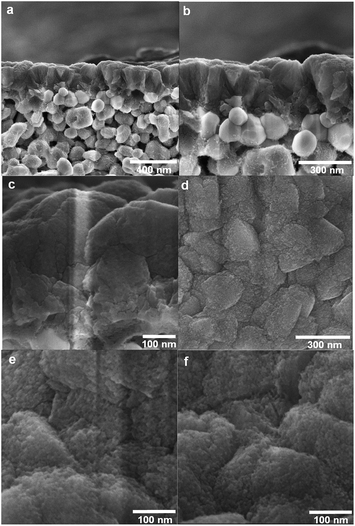 | ||
| Fig. 1 Cross-sectional (a, b and c) and top-view (d and e) SEM images recorded for a non-coked as-synthesised membrane; top-view SEM image (f) recorded for a membrane coked for 25 h. | ||
To carefully characterise the size and distribution of flow-through defects in the membranes, we have significantly advanced a non-destructive technique referred to as permporometry.12,17 In this technique, helium permeance through the membrane is measured as a function of n-hexane relative pressure (P/P0). As the relative pressure of n-hexane in the feed is increased (in a step-wise manner), first zeolite pores and then increasingly larger defects are blocked by n-hexane, and, therefore, the helium permeance is gradually decreased. The amount of defects in terms of relative areas can then be estimated from the permporometry data. The evaluation procedure is described in the ESI.† For this study, a particularly defective membrane according to permporometry was selected in order to better investigate the effect of modification. Table 1 shows permporometry data recorded for the membrane before modification. For the selected membranes, the helium permeance at a relative pressure of n-hexane of 0, i.e. the permeance through zeolite pores and defects, was very high amounting to ca. 130 × 10−7 mol s−1 m−2 Pa−1, which shows that the membrane is a high-permeance membrane with fully open and permeable zeolite pores. The high permeance is mainly a result of the very low zeolite film thickness. In our previous studies,12,18 we showed that the helium permeance recorded at a relative pressure of n-hexane of ca. 2.2 × 10⁻⁴ corresponded to the helium permeance through all defects. For this membrane, the total helium permeance through defects was unusually high, i.e. 35 × 10−7 mol s−1 m−2 Pa−1, with a total relative area of defects of ca. 2% of the membrane area (see Table 1), indicating that the selected membrane was quite defective. By comparison, the total relative area of defects in our high-quality MFI membranes is normally less than 0.5%,6,9,19 resulting in the permeance through defects less than 7 × 10⁻⁷ mol s−1 m−2 Pa−1. The main type of defect in the selected membrane (ca. 99.4% of all defects) was microporous defects, i.e. defects <2 nm in size, and these microporous defects are narrow open grain boundaries. In addition, some mesoporous defects (2–50 nm) were detected by permporometry, however, in a much smaller amount (ca. 0.01% of the total membrane area). Due to the presence of various kinds of defects and high initial permeance, this membrane should be an ideal candidate to study the effect of the modification procedure on blocking defects in high-flux MFI membranes.
| P/P0 | He permeance (10−7 mol s−1 m−2 Pa−1) | Defect interval (nm) | Relative area of defectsa (%) |
|---|---|---|---|
| a Area of defects per total membrane area. | |||
| 0 | 128 | — | |
| 2.2 × 10⁻⁴ | 35 | 0.71–0.73 | 0.34 |
| 3.7 × 10⁻⁴ | 32 | 0.73–0.80 | 0.71 |
| 1.1 × 10⁻³ | 23 | 0.80–1.04 | 0.69 |
| 1.1 × 10⁻² | 10 | 1.04–1.78 | 0.21 |
| 1.1 × 10⁻¹ | 1.4 | 1.78–4.22 | 0.0057 |
| 3.5 × 10⁻¹ | 0.88 | >4.22 | 0.0065 |
| Total: | 1.96 | ||
After the permporometry characterisation, any traces of n-hexane were removed from the membrane by first flushing with pure helium at 50 °C overnight and then calcination in air at 350 °C for 15 h. It should be noted that this specifically designed procedure for the removal of n-hexane from the membrane results in the same initial helium permeance after the permporometry test as it was before the experiment. Hence, no zeolite pores and defects should remain blocked by n-hexane. Thereafter, the feed was changed to helium saturated with iso-propanol at 20 °C. Unlike heavier alcohols, iso-propanol has been shown20 to result in mild coke formation in MFI zeolites via dehydration at 350–400 °C. The mild coke formation is preferred, as it should reduce the risk of blocking the zeolite pores in the membranes. In addition, iso-propanol was found to dehydrate more rapidly than its linear isomer.20 These factors make iso-propanol an ideal candidate for the defect-patching method based on coking. The membrane temperature during the treatment was kept constant at 350 °C to ensure only mild coke formation. The duration of the treatment was varied between 1 and 25 hours to study the effect of treatment (coking) time. After each treatment, the membrane was flushed with pure helium overnight and cooled to 50 °C. Then, the total helium permeance (n-hexane P/P0 = 0) and the helium permeance through all defects (n-hexane P/P0 = 2.2 × 10⁻⁴) were measured. Prior to each new treatment with iso-propanol, the membrane was again flushed with helium and calcined in air for 15 h at 350 °C to remove n-hexane and coke from the previous treatment. It should be noted that unlike many other defect-patching methods, the developed method can be readily applied to membranes already mounted in the modules (in situ modification), resulting in a high practical value of the method. Fig. 2 shows total helium permeance, helium permeance through zeolite pores and helium permeance through defects as a function of coking time. All permeances were decreasing with increasing duration of coking. However, the permeance through zeolite pores was reduced to a much smaller extent than the permeance through defects. Fig. 3 shows relative reduction of helium permeance through defects and zeolite pores as a function of coking time. As the coking time was increased to 3 h, the permeance through defects was reduced by almost 60%. A further increase of the coking time from 3 to 25 h resulted in a much more gradual reduction of permeance through defects by about an additional 10%, reaching a total of 70%. This fact indicates that a 3-hour treatment can be sufficient to block the majority of microporous defects. Although the permeance through defects decreased significantly, the permeance through zeolite pores was only reduced by about 10% or less. This demonstrates that the developed coking procedure is quite selective. Any external surface of the zeolite, such as the grain boundary, is rich in silanol groups, ![[triple bond, length as m-dash]](https://www.rsc.org/images/entities/char_e002.gif) Si–OH due to the missing
Si–OH due to the missing ![[triple bond, length as m-dash]](https://www.rsc.org/images/entities/char_e002.gif) Si–O–Si
Si–O–Si![[triple bond, length as m-dash]](https://www.rsc.org/images/entities/char_e002.gif) bonds.21 These groups should have an affinity for alcohol. At elevated temperature, the silanol groups should react with iso-propanol, first forming
bonds.21 These groups should have an affinity for alcohol. At elevated temperature, the silanol groups should react with iso-propanol, first forming ![[triple bond, length as m-dash]](https://www.rsc.org/images/entities/char_e002.gif) Si–O–C3H7 in a dehydration reaction and then coke,
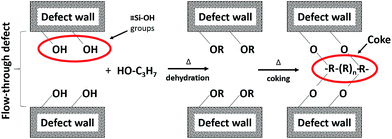
Si–O–C3H7 in a dehydration reaction and then coke, ![[triple bond, length as m-dash]](https://www.rsc.org/images/entities/char_e002.gif) Si–O–R, thereby selectively blocking the defects, as schematically illustrated in Fig. 4. This mechanism can also explain the gradual decrease of the permeance through defects after 5 h of coking. Most likely, the majority of accessible silanol groups should have reacted during the first 5 hours of treatment, causing a much slower blocking process as the treatment time increases further. We should also point out that in the method development stage, benzene, being a common coke precursor, was also tested for blocking the defects by coking. However, the results of the modification with benzene were not as promising as with iso-propanol. For instance, after coking with benzene for 4 h, the permeance through defects was reduced by less than 50%, whereas the permeance through zeolite pores was reduced by about 20%, most likely due to the absence of a distinct affinity of the defects for benzene.
Si–O–R, thereby selectively blocking the defects, as schematically illustrated in Fig. 4. This mechanism can also explain the gradual decrease of the permeance through defects after 5 h of coking. Most likely, the majority of accessible silanol groups should have reacted during the first 5 hours of treatment, causing a much slower blocking process as the treatment time increases further. We should also point out that in the method development stage, benzene, being a common coke precursor, was also tested for blocking the defects by coking. However, the results of the modification with benzene were not as promising as with iso-propanol. For instance, after coking with benzene for 4 h, the permeance through defects was reduced by less than 50%, whereas the permeance through zeolite pores was reduced by about 20%, most likely due to the absence of a distinct affinity of the defects for benzene.
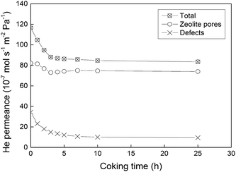 | ||
| Fig. 2 Total helium permeance, helium permeance via zeolite pores and helium permeance via defects measured for the membrane as a function of coking time. The lines are only a guide for the eye. | ||
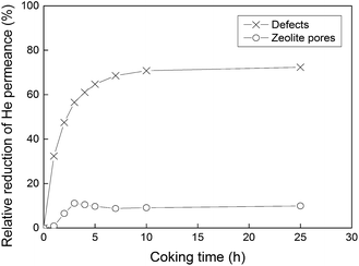 | ||
| Fig. 3 Relative reduction (%) of helium permeance through defects and zeolite pores as a function of coking time. The lines are only a guide for the eye. | ||
After the coking experiments were completed, the membrane coked for 25 h was fully characterised by permporometry, see Table 2. The amount of both microporous and mesoporous defects was reduced. However, the amount of microporous defects was reduced to a much greater extent than that of mesoporous defects, indicating that the developed method should be more effective in blocking microporous defects. We can also note that the total helium permeance (ca. 90 × 10−7 mol s−1 m−2 Pa−1) for the coked membrane compares well with that for the non-coked membranes with a similar amount of defects reported by our group earlier.12
| P/P0 | He permeance (10−7 mol s−1 m−2 Pa−1) | Defect interval (nm) | Relative area of defectsa (%) |
|---|---|---|---|
| a Area of defects per total membrane area. | |||
| 0 | 89 | — | |
| 2.2 × 10⁻⁴ | 9.5 | 0.71–0.73 | 0.17 |
| 3.7 × 10⁻⁴ | 7.8 | 0.73–0.80 | 0.29 |
| 1.1 × 10⁻³ | 4.3 | 0.80–1.04 | 0.14 |
| 1.1 × 10⁻² | 1.7 | 1.04–1.78 | 0.015 |
| 1.1 × 10⁻¹ | 1.0 | 1.78–4.22 | 0.0034 |
| 3.5 × 10⁻¹ | 0.73 | >4.22 | 0.0053 |
| Total: | 0.63 | ||
Fig. 1 shows the top-view HR-SEM images of a non-coked as-synthesised membrane (e) and the membrane coked for 25 h (f). No difference between the two samples could be observed, indicating that the deposited coke layer should be very thin, rendering the coked membrane highly permeable. It should be pointed out, however, that a very thin layer of carbon (coke) will be transparent even in an HR-SEM, and this is probably the case here. We shall also add that it is well known that coke formation (deposition) is minimal in high-silica MFI zeolites, as in the present work (Si/Al = 139). One can therefore expect that a lower Si/Al ratio may cause somewhat greater coke formation in zeolite pores, resulting in lower permeance through the pores after the modification. Gayubo et al.20 studied the deactivation of high-alumina MFI (Si/Al = 28) catalysts by coke deposition during the transformation of iso-propanol into heavier hydrocarbons. The authors found that at relatively low temperatures, i.e. below 400 °C, as in the present work, the deactivation due to coke deposition was very low, despite the high density of the acid sites. This shows that the developed method should also be applicable to MFI membranes with higher aluminium content.
In order to study the effect of the modification procedure on membrane separation performance, the membrane coked for 25 h was evaluated for the separation of an equimolar mixture of n-hexane and 1,3,5-trimethylbenzene (TMB). In our earlier studies,12,13 we demonstrated that this separation system was an ideal system to use for studying the effect of defects on the separation performance. Furthermore, the separation data, which are also an indication of membrane quality, were in excellent agreement with the permporometry data. Fig. 5 shows the n-hexane/TMB separation factor measured for the coked membrane in the present work. The figure also shows the separation factor as a function of the relative area of defects larger than 0.75 nm, i.e. the defects permeable for TMB (TMB kinetic diameter = 0.75 nm) for three as-synthesised membranes with different qualities, i.e. amount of defects, obtained in our previous work.12 From the correlation between the separation factor and the relative area of defects >0.75 nm obtained in the previous work, one can see that for a membrane with a relative area of those defects of 0.46% as for the coked membrane, the n-hexane/TMB separation factor should be about 12. In the present work, we measured the separation factor to be 11.3, indicating a perfect agreement with the previous data. This should also indicate that the amount of defects measured by permporometry for the coked membrane should be reliable as well as the data for the modification method.
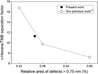 | ||
| Fig. 5 n-Hexane/TMB separation factor as a function of relative area of defects larger than 0.75 nm. The lines are only a guide for the eye. | ||
Conclusions
We have developed a facile method for plugging defects in high-flux MFI membranes. The method based on coking of iso-propanol is selective, reducing the permeance through defects by as much as 70%, while keeping the permeance through zeolite pores high, ca. 90% of its original value. In addition, the method is very practical as it can be easily adapted for blocking defects in membranes already mounted in the module (in situ modification).Acknowledgements
Bio4Energy and the Swedish Energy Agency are gratefully acknowledged for financially supporting this work.Notes and references
- D. S. Sholl and R. P. Lively, Nature, 2016, 532, 435–437 CrossRef PubMed.
- B. Seoane, J. Coronas, I. Gascon, M. E. Benavides, O. Karvan, J. Caro, F. Kapteijn and J. Gascon, Chem. Soc. Rev., 2015, 44, 2421–2454 RSC.
- N. Rangnekar, N. Mittal, B. Elyassi, J. Caro and M. Tsapatsis, Chem. Soc. Rev., 2015, 44, 7128–7154 RSC.
- N. Kosinov, J. Gascon, F. Kapteijn and E. J. M. Hensen, J. Membr. Sci., 2016, 499, 65–79 CrossRef CAS.
- K. V. Agrawal, B. Topuz, T. C. T. Pham, T. H. Nguyen, N. Sauer, N. Rangnekar, H. Zhang, K. Narasimharao, S. N. Basahel, L. F. Francis, C. W. Macosko, S. Al-Thabaiti, M. Tsapatsis and K. B. Yoon, Adv. Mater., 2015, 27, 3243–3249 CrossRef CAS PubMed.
- D. Korelskiy, M. Grahn, P. Ye, M. Zhou and J. Hedlund, RSC Adv., 2016, 6, 65475–65482 RSC.
- Z. P. Lai, G. Bonilla, I. Diaz, J. G. Nery, K. Sujaoti, M. A. Amat, E. Kokkoli, O. Terasaki, R. W. Thompson, M. Tsapatsis and D. G. Vlachos, Science, 2003, 300, 456–460 CAS.
- M. Zhou, D. Korelskiy, P. Ye, M. Grahn and J. Hedlund, Angew. Chem., Int. Ed., 2014, 53, 3492–3495 CrossRef CAS PubMed.
- D. Korelskiy, P. Ye, S. Fouladvand, S. Karimi, E. Sjöberg and J. Hedlund, J. Mater. Chem. A, 2015, 3, 12500–12506 CAS.
- A. G. Slater and A. I. Cooper, Science, 2015, 348 Search PubMed.
- H. Maghsoudi, Sep. Purif. Rev., 2016, 45, 169–192 CrossRef CAS.
- D. Korelskiy, M. Grahn, J. Mouzon and J. Hedlund, J. Membr. Sci., 2012, 417–418, 183–192 CrossRef CAS.
- D. Korelskiy, P. Ye, H. Zhou, J. Mouzon and J. Hedlund, Microporous Mesoporous Mater., 2014, 186, 194–200 CrossRef CAS.
- J. Choi, H.-K. Jeong, M. A. Snyder, J. A. Stoeger, R. I. Masel and M. Tsapatsis, Science, 2009, 325, 590–593 CrossRef CAS PubMed.
- S. Karimi, D. Korelskiy, L. Yu, J. Mouzon, A. Ali Khodadadi, Y. Mortazavi, M. Esmaeili and J. Hedlund, J. Membr. Sci., 2015, 489, 270–274 CrossRef CAS.
- Y. Zhang, A. M. Avila, B. Tokay, H. H. Funke, J. L. Falconer and R. D. Noble, J. Membr. Sci., 2010, 358, 7–12 CrossRef CAS.
- J. Hedlund, D. Korelskiy, L. Sandström and J. Lindmark, J. Membr. Sci., 2009, 345, 276–287 CrossRef CAS.
- J. Hedlund, M. Grahn, D. Korelskiy, M. Rayson, S. Öberg and P. R. Briddon, J. Membr. Sci., 2012, 415–416, 271–277 CrossRef CAS.
- D. Korelskiy, T. Leppäjärvi, H. Zhou, M. Grahn, J. Tanskanen and J. Hedlund, J. Membr. Sci., 2013, 427, 381–389 CrossRef CAS.
- A. G. Gayubo, A. T. Aguayo, A. Atutxa, R. Aguado and J. Bilbao, Ind. Eng. Chem. Res., 2004, 43, 2610–2618 CrossRef CAS.
- A. Farzaneh, M. Zhou, O. N. Antzutkin, Z. Bacsik, J. Hedlund, A. Holmgren and M. Grahn, Langmuir, 2016, 32, 11789–11798 CrossRef CAS PubMed.
Footnote |
| † Electronic supplementary information (ESI) available. See DOI: 10.1039/c7ta01268c |
| This journal is © The Royal Society of Chemistry 2017 |

