 Open Access Article
Insights into the reversibility of aluminum graphite batteries†
Giuseppe Antonio
Elia‡
*a,
Ivana
Hasa‡
bc,
Giorgia
Greco
 d,
Thomas
Diemant
e,
Krystan
Marquardt
a,
Katrin
Hoeppner
a,
R. Jürgen
Behm
be,
Armin
Hoell
d,
Stefano
Passerini
d,
Thomas
Diemant
e,
Krystan
Marquardt
a,
Katrin
Hoeppner
a,
R. Jürgen
Behm
be,
Armin
Hoell
d,
Stefano
Passerini
 *bc and
Robert
Hahn
*f
aTechnische Universität Berlin, Research Center of Microperipheric Technologies, Gustav-Meyer-Allee 25, D-13355 Berlin, Germany. E-mail: elia@tu-berlin.de
bHelmholtz Institute Ulm, Helmholtzstraße 11, D-89081 Ulm, Germany. E-mail: stefano.passerini@kit.edu
cKarlsruhe Institute of Technology, P.O. Box 3640, D-76021 Karlsruhe, Germany
dHelmholtz-Zentrum Berlin für Materialien und Energie GmbH, Albert-Einstein-Straße 15, D-12489 Berlin, Germany
eUlm University, Institute of Surface Chemistry and Catalysis, Albert-Einstein-Allee 47, D-89081 Ulm, Germany
fFraunhofer-Institut für Zuverlässigkeit und Mikrointegration, Gustav-Meyer-Allee 25, D-13355 Berlin, Germany. E-mail: robert.hahn@izm.fraunhofer.de
First published on 20th April 2017
Abstract
Herein we report a novel study on the reaction mechanism of non-aqueous aluminum/graphite cell chemistry employing 1-ethyl-3-methylimidazolium chloride:aluminum trichloride (EMIMCl:AlCl3) as the electrolyte. This work highlights new insights into the reversibility of the anion intercalation chemistry besides confirming its outstanding cycle life exceeding 2000 cycles, corresponding to more than 5 months of cycling test. The reaction mechanism, involving the intercalation of AlCl4− in graphite, has been fully characterized by means of ex situ X-ray diffraction (XRD), X-ray photoelectron spectroscopy (XPS), X-ray absorption near edge structure spectroscopy (XANES) and small-angle X-ray scattering (SAXS), evidencing the accumulation of anionic species into the cathode as the main factor responsible for the slight initial irreversibility of the electrochemical process.
Introduction
Aluminum is an interesting anode material for electrochemical energy storage due to its extremely high volumetric capacity of 8040 mA h cm−3, four times higher than that of lithium, and a favorable gravimetric capacity of 2980 mA h g−1. Furthermore, aluminum is the third most abundant element in the earth's crust and can be handled in an ambient atmosphere leading to enormous advantages for cell manufacturing.1,2 A limited number of materials exhibited reversible intercalation of trivalent Al3+ ions, such a Mo6S8,3 V2O5![[thin space (1/6-em)]](https://www.rsc.org/images/entities/char_2009.gif) 4,5 and VO2,6 most likely due to the extremely high charge density, in spite of its small ionic radius (0.39 Å versus 0.59 Å of Li+).7 Accordingly, the most promising non-aqueous aluminum batteries in terms of performance employ electrochemical conversion8–11 or anion intercalation2,12–14 processes at the positive electrode. The anion intercalation chemistry involved at the cathode appears to be a promising process for the realization of electrochemical storage devices called dual ion cells.15,16 In particular the use of nanostructured carbon materials or graphene2,12 allows extremely high power densities, close to those of supercapacitors. Indeed, AlCl4− is characterized by excellent stability and fast diffusion in the graphite planes,2,12 thus making graphite-based AlCl4− intercalation cathodes appealing for aluminum batteries, as well as other dual ion chemistries.17
4,5 and VO2,6 most likely due to the extremely high charge density, in spite of its small ionic radius (0.39 Å versus 0.59 Å of Li+).7 Accordingly, the most promising non-aqueous aluminum batteries in terms of performance employ electrochemical conversion8–11 or anion intercalation2,12–14 processes at the positive electrode. The anion intercalation chemistry involved at the cathode appears to be a promising process for the realization of electrochemical storage devices called dual ion cells.15,16 In particular the use of nanostructured carbon materials or graphene2,12 allows extremely high power densities, close to those of supercapacitors. Indeed, AlCl4− is characterized by excellent stability and fast diffusion in the graphite planes,2,12 thus making graphite-based AlCl4− intercalation cathodes appealing for aluminum batteries, as well as other dual ion chemistries.17
In this work, we report a thorough investigation of the AlCl4− intercalation mechanism into graphite in cells comprising an aluminum anode and an EMIMCl:AlCl3 electrolyte via electrochemical methods coupled with ex situ X-ray diffraction (XRD), X-ray photoelectron spectroscopy (XPS), X-ray absorption near edge structure spectroscopy (XANES) and small-angle X-ray scattering (SAXS) measurements. A clear understanding of the electrochemical process, including the explanation of the irreversible process characteristics of the system is provided. For the first time, the accumulation of anionic species into the cathode is revealed, which we consider to be mainly responsible for the slight irreversibility of the electrochemical process. This irreversible process leads to a structural reorganization of the graphitic cathode, allowing an increased anion uptake upon cycling and faster anion diffusion after long-term cycling, resulting in the improvement of the cell's cycling performance.
Finally, the work highlights the key role of the solvent employed during the rinsing step of electrodes subjected to post-mortem analysis, indicating that the electrode rinsing procedure may induce structural changes on the cycled electrodes, thus producing some controversial results.2,13
Experimental
The electrolyte, 1-ethyl-3-methylimidazolium chloride:aluminum trichloride (EMIMCl):AlCl3 in a 1![[thin space (1/6-em)]](https://www.rsc.org/images/entities/char_2009.gif) :
:![[thin space (1/6-em)]](https://www.rsc.org/images/entities/char_2009.gif) 1.5 mole ratio, was provided by Solvionic with a water content lower than 100 ppm. The mole ratio between the EMIMCl and the AlCl3 is a fundamental parameter influencing the properties of the electrolyte solution. The system is defined basic, neutral or acidic when the EMIMCl/AlCl3 mole ratio is, respectively, higher, equal or lower than one. In acid melts the dominant species is Al2Cl7−, in the neutral melt the only anionic species is AlCl4− and in basic melts AlCl4− and Cl− species coexist. The reversible aluminum stripping deposition process is possible only in acid melts. Accordingly an acidic electrolyte solution, namely EMIMCl:AlCl3 1
1.5 mole ratio, was provided by Solvionic with a water content lower than 100 ppm. The mole ratio between the EMIMCl and the AlCl3 is a fundamental parameter influencing the properties of the electrolyte solution. The system is defined basic, neutral or acidic when the EMIMCl/AlCl3 mole ratio is, respectively, higher, equal or lower than one. In acid melts the dominant species is Al2Cl7−, in the neutral melt the only anionic species is AlCl4− and in basic melts AlCl4− and Cl− species coexist. The reversible aluminum stripping deposition process is possible only in acid melts. Accordingly an acidic electrolyte solution, namely EMIMCl:AlCl3 1![[thin space (1/6-em)]](https://www.rsc.org/images/entities/char_2009.gif) :
:![[thin space (1/6-em)]](https://www.rsc.org/images/entities/char_2009.gif) 1.5 mole ratio, has been selected as the electrolyte for this study. Electrochemical measurements were performed using Teflon Swagelok® T-type cells. All potentials quoted in this manuscript refer to the quasi-reference Al/Al3+ electrode.
1.5 mole ratio, has been selected as the electrolyte for this study. Electrochemical measurements were performed using Teflon Swagelok® T-type cells. All potentials quoted in this manuscript refer to the quasi-reference Al/Al3+ electrode.
The electrolyte anodic and cathodic stability was evaluated by linear sweep voltammetry (scan rate of 0.1 mV s−1), using a three electrode configuration with glassy carbon rods as the working and counter electrodes, and aluminum wire as the reference electrode.2 The cycling stability of the aluminum metal (Al 99.99% Alfa Aesar) in the ionic liquid-based electrolyte was evaluated by continuous stripping/deposition tests on symmetrical Al/Al cells. The electrochemical characterization of the complete (Al//PG) cells was performed using aluminum metal as the counter electrode, a GF/A Whatman® glass fiber soaked by the electrolyte as separator and a pyrolytic graphite disk (Panasonic PG, 100 μm thickness, 8.66 mg cm−2 loading, herein named PG for brevity) as the working electrode. The specific currents (mA g−1) and the specific capacities (mA h g−1) in the whole manuscript are referred to the cathode (PG) weight. The cycling tests of Al/EMIMCl:AlCl3/PG cells were carried out by applying increasing specific currents (from 25 to 100 mA g−1) in the voltage range of 0.4–2.4 V, and for the long term cycling test a current rate of 25 mA g−1 was applied for the first five cycles and a current rate of 75 mA g−1 for the following cycles. All galvanostatic cycling tests were carried out at 25 °C in a thermostatic climatic chamber (with a possible deviation of ±1 °C), using a Maccor 4000 Battery Test System.
The ex situ morphological characterization was performed using a high-resolution scanning electron microscope (FE-SEM, Zeiss Auriga) equipped with a field emission electron gun as the electron source and an in-lens detector. The acceleration voltage was set to 3 kV.
The structural analysis was accomplished by XRD using Cu Kα radiation (0.154056 nm) on a Bruker D8 Advance diffractometer in the 2θ range from 10° to 90° with a step size of 0.01° using a dome-shaped, air-tight sample holder.
The chemical surface composition was determined by XPS measurements (PHI5800 ESCA System, Physical Electronics) using monochromatized Al Kα radiation, a take-off angle of 45° for photoelectrons from the samples, and pass energies at the analyzer of 93.9 eV and 29.35 eV for survey and detail measurements, respectively. The main C (1s) peak was set to 284.5 eV for binding energy (BE) calibration. The C 1s detail spectra were deconvoluted using the CasaXPS software package (Casa Software).
XANES and SAXS measurements were carried out using the synchrotron beamline FCM (Four Crystal Monochromator) of the Physikalisch Technische Bundesanstalt (PTB) laboratory at the synchrotron light source BESSY II of the Helmholtz-Zentrum Berlin für Materialien und Energie GmbH. The beamline is equipped with an anomalous SAXS (ASAXS) instrument designed and constructed by the Helmholtz-Zentrum Berlin für Materialien und Energie GmbH.18 The storage ring operated in top-up mode with a ring current of 250 mA. The four-crystal monochromator of FCM beamline set-up delivers a flux of up to 1010 photons per s in the energy range between 3 and 10 keV (Si(111) crystals) and an even higher flux between 1.8 keV and 3 keV (InSb(111) crystals).19 For SAXS experiment the cross section of the primary beam at the sample position was 0.5 mm × 0.5 mm (width × height), the sample-detector distances were 3721 mm and 1426 mm, as determined by calibration with Ag-behenate (long period, d001 = 5.8380 nm) and the photon energy of 10 keV, equivalent to a wavelength of λ = 0.1239 nm. The detector used for SAXS is an in-vacuum version of a PILATUS 1M.20 Scattering patterns are recorded with an exposure time of 5 s. The obtained patterns cover the region of 0.05 nm−1 ≤ Q ≤ 4.2 nm−1, where Q is defined as Q = (4π/λ)sin(2θ/2), 2θ is the scattering angle. XANES measurements were performed in the fluorescence mode at the Cl K-edge (2822.4 eV, monochromator crystals InSb(111)) by using a Bruker X-Flash 125 eV SDDLN2 detector. The incoming beam intensity was monitored by using a pin photodiode, 7 μm thick, which was calibrated against a cryogenic electric substitution radiometer.21
Prior to the ex situ analyses, the studied electrodes were rinsed in order to remove residual electrolyte. Different solvents were employed to evaluate the impact of rinsing on the chemical and structural properties of the cathode electrodes. The solvents used, i.e. methanol, acetonitrile and dimethyl carbonate, were rigorously anhydrous and the water content was detected by the Karl Fischer titration method.
Results and discussion
Prior to the investigation of the AlCl4− intercalation in graphite, the properties of the electrolyte solution, i.e. EMIMCl:AlCl3 (mole ratio 1![[thin space (1/6-em)]](https://www.rsc.org/images/entities/char_2009.gif) :
:![[thin space (1/6-em)]](https://www.rsc.org/images/entities/char_2009.gif) 1.5), were studied. Fig. S1a† shows that the electrochemical stability window of the EMIMCl:AlCl3 electrolyte is only anodically limited at 2.45 V. The increased current flow observed at potentials higher than 2.45 V is, in fact, associated with the oxidation of the AlCl4− anion.22,23 On the other hand, at potentials below −0.05 V aluminum metal deposition on the glassy carbon current collector occurs.22,23 In fact, as shown in Fig. S1b,† aluminum can be reversibly plated and stripped in a symmetrical Al/EMIMCl:AlCl3/Al cell, with a rather limited polarization (<20 mV).24,25 This value is comparable with that obtained for the dissolution/deposition of lithium in ionic liquid-based electrolytes.26
1.5), were studied. Fig. S1a† shows that the electrochemical stability window of the EMIMCl:AlCl3 electrolyte is only anodically limited at 2.45 V. The increased current flow observed at potentials higher than 2.45 V is, in fact, associated with the oxidation of the AlCl4− anion.22,23 On the other hand, at potentials below −0.05 V aluminum metal deposition on the glassy carbon current collector occurs.22,23 In fact, as shown in Fig. S1b,† aluminum can be reversibly plated and stripped in a symmetrical Al/EMIMCl:AlCl3/Al cell, with a rather limited polarization (<20 mV).24,25 This value is comparable with that obtained for the dissolution/deposition of lithium in ionic liquid-based electrolytes.26
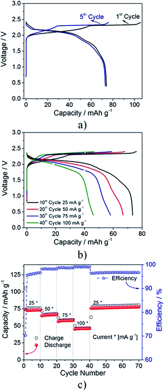
Overall the anodic stability and excellent Al dissolution/deposition performance of the electrolyte allow the investigation of the anion intercalation in pyrolytic graphite. Fig. 1a shows the voltage profile of an Al/EMIMCl:AlCl3/PG (pyrolytic graphite) cell cycled at a constant current of 25 mA g−1. During the first cycle (black curve), the cell shows a specific charge capacity of 105 mA h g−1 and a discharge capacity of 75 mA h g−1 with an overall coulombic efficiency of about 70%. It is not excluded that the irreversible capacity observed during the first (dis)charge cycle may be ascribed to the partial irreversibility of the anion intercalation process, suggesting the incomplete de-insertion of the intercalated species from the graphite cathode (as indeed evidenced later by the ex situ XRD, XPS, XANES and SAXS measurements). However, partial oxidative decomposition of impurities and/or small traces of water present in the electrolyte cannot be excluded. Nevertheless, after a few cycles (see 5th cycle in blue) the electrochemical process exhibits very high reversibility (the coulombic efficiency increases to almost 96%) and average working voltage (about 1.9 V). The shape of the voltage profile reflects the typical anion intercalation process within the layered structure of graphite2,12–14,27–29 with plateaus indicating the characteristic multi-stage process.2,16 The electrochemical process occurring upon anion intercalation is further confirmed by the cyclic voltammetry test reported in Fig. S2a.† The voltammogram clearly evidences the presence of three peaks during the anodic scan at 1.85, 2.15 and 2.35 V and three reversible processes occurring at 1.77, 2.05 and 2.17 V, which are associated with the multistage anion intercalation in-between the graphite layers.2,16
Fig. 1b illustrates the voltage signature of the Al/EMIMCl:AlCl3/PG cell galvanostatically cycled at different current rates. The measurement evidences a decrease of the delivered capacity with increasing current values and as expected, an increase of the average cell polarization of about 0.15 V going from 25 mA g−1 to 50 mA g−1. However, only a limited cell polarization increase is observed when raising the current to 100 mA g−1 (see Fig. S2b†). Fig. 1c reports the overall cycling behavior upon the rate capability test, revealing the good cyclability with satisfactory coulombic efficiency, particularly at higher current rates, evidencing the overall good stability of the investigated cell. The higher coulombic efficiencies upon increasing currents can most likely be ascribed to kinetic limitations of the side reactions.
In order to fully understand the anion intercalation mechanism involved in the cell operation, ex situ measurements employing different techniques were performed. However, it is well known that the electrode rinsing process, necessary to remove the electrolyte prior to executing the post-mortem analysis, may strongly affect the electrode chemistry. Thus, the role of the solvent used for the electrode rinsing was investigated by employing a few anhydrous solvents. This allowed the comparison with previously reported studies,2,13 leading to a clarification of the structural characteristics of the cycled graphite electrodes. In order to evaluate the best solvent for electrolyte removal, ex situ XRD analysis was performed on fully charged PG electrodes as recovered from the cell (i.e., without the rinsing process)2 and after rinsing with methanol,13 acetonitrile or dimethyl carbonate (Fig. 2). The comparison with the non-rinsed electrode shows that both methanol and acetonitrile strongly affect the structural properties of the charged PG while dimethyl carbonate (DMC) does not, underlining the importance of the rinsing solvent for the obtainment of reliable and reproducible results of anion-intercalated graphite.
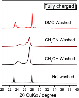 | ||
| Fig. 2 Effect of the rinsing process on the charged PG electrode. Ex situ X-ray diffractogram comparison of the fully charged PG electrode (not washed) and washed employing various solvents. | ||
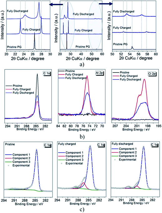
Fig. 3a reports the ex situ X-ray diffractograms of pristine, fully charged and fully discharged PG electrodes after rinsing with DMC. The pristine PG electrode exhibits the conventional graphite (002) reflection at 2θ = 26.42° (d spacing 3.46 Å). Upon full charge, the diffractogram reveals the disappearance of the main graphitic peak and the appearance of two new reflections associated with the (00n + 1) and (00n + 2) periodic arrays of intercalated layers in-between the graphene planes, where n indicates the stage number (respectively associated with the most intense and the second most intense reflections). The two new reflections appear at 2θ = 23.17° (d spacing 3.92 Å) and at 27.96° (d spacing 3.28 Å), associated with the (00n + 2) and (00n + 1) reflections, respectively. Under the experimental conditions, the calculated ratio between d(00n+2)/d(00n+1) is 1.2. According to the standard values listed in Table S1,†15,30,31 a d(00n+2)/d(00n+1) of 1.2 indicates that upon full charge a stage 4 graphite intercalation compound (GIC) is obtained.15,16,30,32
It is widely known that stages (n) of GICs can be associated with the periodic distance (Ic), the gallery expansion (Δd) and the intercalant gallery height (di), according to eqn (1):15,16,30,32
| Ic = di + 3.35 Å × (n − 1) = Δd + (3.35 Å × n) = l × dobs | (1) |
![[thin space (1/6-em)]](https://www.rsc.org/images/entities/char_2009.gif) 33–36). Upon full discharge, however, the structure of the graphite cathode is only partially recovered, supporting the partial irreversibility of the process, likely due to the trapping of a small amount of AlCl4− between the graphite layers. The (002) reflection observed for the pristine electrode disappears upon the first charging and is not recovered after the discharge process.2 On the other hand, the two new reflections shifted to 24.27° (associated with the (00n + 2) reflection, calculated d spacing 3.74 Å) and 27.46° (associated with the (00n + 1) reflection, calculated d spacing 3.33 Å) can be noticed. The determination of the d(00n+2)/d(00n+1) ratio calculated for the discharged material is 1.12. The most dominant stage is identified by correlating the calculated ratio with that of pure GICs (see Table S1†). Accordingly, in our study a d(00n+2)/d(00n+1) ratio equal to 1.12 indicates a stage 7 intercalation compound,16,32i.e., guest species are in average intercalated at every 7th graphene layer. However, according to eqn (1),16,32 the Δd gallery expansion is 6.49 Å, which is comparable to that calculated for the fully charged material. This further support the trapping of part of the intercalated guest species, AlCl4−.
33–36). Upon full discharge, however, the structure of the graphite cathode is only partially recovered, supporting the partial irreversibility of the process, likely due to the trapping of a small amount of AlCl4− between the graphite layers. The (002) reflection observed for the pristine electrode disappears upon the first charging and is not recovered after the discharge process.2 On the other hand, the two new reflections shifted to 24.27° (associated with the (00n + 2) reflection, calculated d spacing 3.74 Å) and 27.46° (associated with the (00n + 1) reflection, calculated d spacing 3.33 Å) can be noticed. The determination of the d(00n+2)/d(00n+1) ratio calculated for the discharged material is 1.12. The most dominant stage is identified by correlating the calculated ratio with that of pure GICs (see Table S1†). Accordingly, in our study a d(00n+2)/d(00n+1) ratio equal to 1.12 indicates a stage 7 intercalation compound,16,32i.e., guest species are in average intercalated at every 7th graphene layer. However, according to eqn (1),16,32 the Δd gallery expansion is 6.49 Å, which is comparable to that calculated for the fully charged material. This further support the trapping of part of the intercalated guest species, AlCl4−.
| Charged electrode | Discharged electrode | |
|---|---|---|
| 2θ (00n + 1)/2θ degree | 27.96 | 27.43 |
| 2θ (00n + 2)/2θ degree | 23.17 | 24.27 |
| d obs(n + 1)/Å | 3.28 | 3.33 |
| d obs(n + 2)/Å | 3.92 | 3.74 |
| d obs(n + 2)/dobs(n + 1) ratio | 1.20 | 1.12 |
| Dominant stage (n) | 4 | 7 |
| Periodic repeat distance (Ic)/Å | 19.64 | 29.94 |
| AlCl4− gallery height (di)/Å | 9.59 | 9.93 |
| AlCl4− gallery expansion (Δd)/Å | 6.24 | 6.49 |
Fig. 3b reports the XPS detail spectra in the Al 2p and Cl 2p regions of the PG electrode in the pristine, fully charged and fully discharged states. The intercalation of AlCl4− is evident from the detail spectra in the Al 2p and Cl 2p regions. In fact, the contributions of Cl and Al are totally absent in the pristine electrode; however, they appear clearly after the first anion intercalation. The C 1s and Al 2p peak intensity decreases in the discharged sample hints, once more, for the partial irreversibility of the electrochemical process as well as to the persistence of some trapped/adsorbed species in the graphite sample.
The intercalation of anion species is also confirmed from the detail spectra in the C 1s region. In order to clarify this aspect, i.e., the carbon components and their evolution upon cycling, peak fitting analysis was performed. Fig. 3c reports the fit of the C 1s feature for the pristine, fully charged and fully discharged PG electrodes. The C 1s spectrum of the pristine sample is dominated by the peak at 284.5 eV, which is assigned to sp2-hybridized carbon atoms in graphite.37,38 Its asymmetric shape, typical for sp2-C, is a consequence of the conductive nature of graphite.38 The second broad and weak peak detected for the pristine electrode at 290.8 eV is a shake-up satellite due to π–π* transitions typically observed for graphite. In the charged electrode, the intensity of the main peak decreases significantly while additional features appear at higher binding energies. Very likely, the peak at the highest binding energy (289.1 eV) is related to residual solvent from the rinsing process.39 The peak at 286.5 eV can be associated with the oxidation of graphite C atoms, occurring upon the intercalation of AlCl4−. This is in agreement with the well-known redox-amphoteric behavior of graphite when used as intercalation host.2,15 However, a contribution of the C–N bond of EMIM+ cannot be excluded, since it occurs at rather similar binding energies.4 This may indicate cation co-intercalation to occur together with AlCl4−. After discharge, the C 1s spectrum of the cathode does not completely revert to that of pristine graphite. Most prominently, the intensity of the main peak is not completely recovered indicating a partial irreversibility of the electrochemical process and suggesting that AlCl4− remains partially intercalated in the graphite planes, thus confirming the XRD results reported in Fig. 2a. For charge neutrality, the partial trapping of AlCl4− anions upon discharge may only occur if EMIM+ cations are inserted.
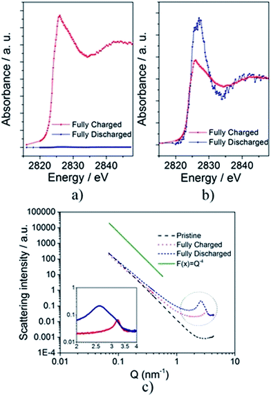
To further investigate the structural/chemical modifications occurring during the first charge–discharge process and to get additional support for the incomplete reversibility of the overall electrochemical process, XANES measurements were performed at the Cl K-edge (Fig. 4). Fig. 4a shows the spectra of the fully charged and discharged PG electrodes after removal of the pre-edge absorption (without normalization to the absorption jump) while the normalized spectra are depicted in Fig. 4b. No signal was detected for the pristine electrode, indicating the absence of chlorine in PG before cycling. The observed absorption discontinuities are proportional to the amount of Cl in the electrode. Their intensity decreases strongly when going from the charged to the discharged electrode with the ratio (JDisch/JCh) being 0.039. Once more, the XANES results indicate that the major part of the intercalated species is removed upon discharge while a certain amount remains intercalated in the PG electrode, in full agreement with the XRD and XPS results.
SAXS patterns of pristine, fully charged and fully discharged electrodes were acquired to obtain valuable information on the formation (and variation) of repeated and regular differences in the average electron density of materials (Fig. 4c). The shape and, especially, the slope (∼Q−4) of the pristine electrode pattern indicate the existence of smooth surfaces. On the other hand, the decreased slope observed for both the cycled electrodes indicates a neat increase of the surface roughness on the nanometer scale. After the first charge, a well pronounced peak appears at Q ≈ 3.22 nm−1, identifying the distance (D approx. equal to 2π/Q) between features regularly appearing in the material (i.e., the distance between sheets of the same electron densities) to be about 1.92 nm. This value is in very good agreement with the periodic distance (Ic = 1.96 nm) calculated from the ex situ X-ray diffraction of the fully charged electrode (see Fig. 3a and 4c and Table 1). After full discharge, the peak shifts to lower Q values, indicating larger distances among sheets. Now the peak appears at Q ≈ 2.66 nm−1, indicating a periodic distance D ≈ 3.09 nm, which is again in good agreement with the periodic distance (Ic = 2.99 nm) calculated from the ex situ X-ray diffraction of the fully discharged electrode (see Fig. 3a and 4c and Table 1). Moreover, in the discharged electrode, the peak appears broadened revealing an increase of the distance-size distribution disorder (see Fig. 4c). The results obtained by the analysis of the SAXS measurements are summarized in Table S2.†
The careful analysis of the above reported results helps clarifying the debate regarding the geometry and diffusion mechanism of AlCl4− in-between the graphite planes. Wu et al.29 indicated that AlCl4− diffuses in-between the graphite planes in a planar geometry, while Jung et al.41 concluded that AlCl4− intercalating into the graphite maintains its tetrahedral geometry. The herein reported experimental results on the intercalant gallery height (di) are in good agreement with the theoretical calculation of Jung et al.,41 supporting that AlCl4− intercalates into graphite maintaining the tetrahedral geometry.
However, based on the results of the extensive characterization of pristine, charged and discharged PG electrodes by different techniques, we conclude that the intercalation process of the AlCl4− into graphite is not completely reversible. The process involves, in fact, the intercalation of AlCl4− anions, and most likely the co-intercalation of EMIM+ cations, during the first charge and discharge, which modifies the graphite structure. Despite the incomplete reversibility of the first electrochemical charge–discharge process, Al/EMIMCl:AlCl3/PG cells behave very reversibly upon further cycling, suggesting that the irreversible behavior in the first cycle corresponds to the activation of the graphite electrode. This reversible behavior is illustrated in Fig. 5a, showing a long-term cycling test (75 mA g−1) of an Al/EMIMCl:AlCl3/PG cell prior to activation at a low current density (five cycles at 25 mA g−1). The test demonstrates the excellent stability of the cell exceeding two thousand cycles without any significant performance decay. Actually, the test reveals a continuous increase of the delivered capacity upon cycling, more evident in the initial cycles, but still present at higher cycle numbers, as evidenced by comparing the 500th and the 1000th cycles (see Fig. 5b). The above cycling results were obtained over a period of time exceeding five months, thus proving the long-time scale stability of the cell. This was not the case in previous studies, where the long-term cycling stability was tested at extremely high current values, resulting in thousands of cycles in a few days2,12,14 (see the comparison in Table S3 in the ESI†).
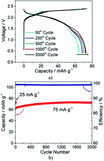 | ||
| Fig. 5 (a) Selected voltage profiles and (b) cycling behavior of the Al/EMIMCl:AlCl3/PG cell cycled at 25 mA g−1 for the first 5 cycles and at 75 mA g−1 for the following cycles (25 °C). | ||
To further confirm the improved cell performance of the cycled graphite electrode, Fig. S3† compares the rate capability test of a Al/EMIMCl:AlCl3/PG cell at the initial stage (black triangles) and after 500 cycles (blue circles). The comparison shows that after 500 (dis)charge cycles the cell delivers more than 65 mA h g−1 at the higher current (100 mA g−1), reflecting an improvement of more than 35% with respect to the initial value (45 mA h g−1).
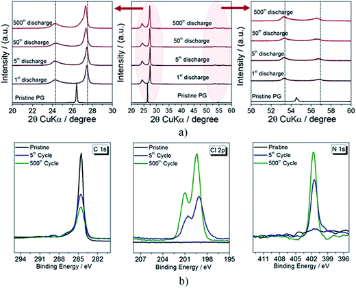
In order to understand the origin of the improved cycling behavior, ex situ XRD and XPS measurements on discharged PG electrodes after different cycle numbers (see Fig. 5a and b) were performed. The XRD diffractograms reveal a general shift of the reflections to lower 2θ values (see magnifications of the 20–30° and 50–60° 2θ range), i.e. to higher d-spacing values. The behavior is clearly evidenced in Fig. S4,† revealing that the calculated d-spacing associated with the main reflection increases during the initial 50 cycles to later stabilize at about 3.264 Å. Such an increase clearly indicates that a structural modification of the electrodes occurs upon cycling, associated with the accumulation of ionic species in-between the graphite layers, resulting in the increased reversible anion intercalation clearly evidenced in Fig. S3† by the delivered capacity and rate capability enhancement.
The main result from the XPS detail spectra in the C 1s region (Fig. 6b) is the progressive reduction of the intensity of the main peak upon cycling, indicating a progressive change of the structural characteristics of the PG cathode most likely associated with the anion accumulation in-between the graphite planes already observed by XRD (see Fig. 3a). The fitting of the C 1s peaks (Fig. S5†), however, shows the intensity increase of the peak at 286.5 eV confirming increased amounts of the species trapped in the structure. Similarly, the Cl 2p peak intensity increases upon cycling, which is a further indication of an increased amount of AlCl4− trapped in-between the graphite layers. However, interesting results are seen in the N 1s region of the XPS spectra. The dominating peak at 401.7 eV, which is assigned to the N atoms in the EMIM+ cation,40 increases upon cycling, further confirming the partial intercalation of EMIM+ cations in-between the graphite layers upon cycling.42–45
In order to complete the surface study of the Al//PG cell XPS analysis of the anode was also performed. Fig. S6† shows the XPS spectra of aluminum electrodes, revealing that substantial modifications of the surface chemical composition occur upon cycling. The Al 2p spectrum of the pristine sample shows two peaks, one at about 72 eV associated with the presence of metallic aluminum37 and a second one at about 74.5 eV associated with the native Al2O3 layer.37 However, the spectra of the cycled samples show the disappearance of the metallic aluminum peak and the shift to slightly higher binding energy of the second one.46,47 Furthermore, the Cl 2p spectrum clearly indicates the formation of chlorine species on the aluminum surface,37 consistent with the presence of AlClx species.
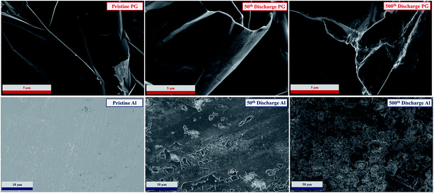
Finally, the evolution of the PG and Al electrode morphologies upon cycling was investigated by ex situ SEM analysis (Fig. 7). The electrodes were taken from cells subjected to 50 and 500 cycles, which were disassembled after a 24 h rest period to allow for full equilibration of the electrodes. Pristine electrodes were also investigated for comparison. The cycled aluminum electrodes reveal an increase of the surface roughness due to the continuous dissolution and deposition process. However, we find no evidence of dendritic deposition, indicating that such metal anodes are suitable candidates for rechargeable cells. The PG electrodes reveal a slight degradation of the surface characterized by the formation of a film on the surface, which is most likely associated with a partial decomposition of the electrolyte, in agreement with the XPS results reported in Fig. 6b.
Conclusions
AlCl4− intercalation into graphite has been investigated using several techniques, including XRD, XPS, XANES and SAXS. Combining the structural, morphological, and electrochemical characterization, details of the processes taking place during the (de)intercalation of chloroaluminate species in a graphite cathode have been gained. In particular, the structural characterization obtained by XRD and SAXS clearly indicates that the intercalation process involves the AlCl4− anion as the principal intercalating species. Furthermore, new insights into the reversibility of the electrochemical process characterizing the aluminum/graphite system have been obtained. The initial irreversibility of the system can be explained by small amounts of AlCl4− retained in the graphite structure. Although this occurs mostly in the first charge–discharge cycle, the amount of anions trapped in the graphite layer slightly increases upon cycling, leading to a structural reorganization of the material, which in turn leads to an improved cell performance. We believe that the results reported in this study clarify important structural aspects of rechargeable cells employing aluminum as the anode material in non-aqueous electrolytes. In light of the reported results, a properly engineered graphite-based cathode may lead to limited retention of the intercalated anion in the graphite, thus improving the reversibility of the electrochemical process and leading to enhanced performance in rechargeable aluminum/graphite cells.Finally, we would like to underline the excellent stability of the Al//PG cell, operating for more than five months with negligible performance fading.
Acknowledgements
This research was funded by the European Commission in the H2020 ALION project under contract 646286 and the German Federal Ministry of Education and Research in the AlSiBat project under contract 03SF0486. The authors are thankful to M. Krumrey for granting permission to use the PTB FCM beamline at BESSY for the SAXS and XANES experiments. The help of E. Gericke to perform these two experiments is acknowledged. We would like to thank SOLVIONIC for providing the electrolyte.References
- G. A. Elia, K. Marquardt, K. Hoeppner, S. Fantini, R. Lin, E. Knipping, W. Peters, J.-F. Drillet, S. Passerini and R. Hahn, Adv. Mater., 2016, 28, 7564–7579 CrossRef CAS PubMed.
- M.-C. Lin, M. Gong, B. Lu, Y. Wu, D.-Y. Wang, M. Guan, M. Angell, C. Chen, J. Yang, B.-J. Hwang and H. Dai, Nature, 2015, 520, 324–328 CrossRef CAS PubMed.
- L. Geng, G. Lv, X. Xing and J. Guo, Chem. Mater., 2015, 27, 4926–4929 CrossRef CAS.
- (a) H. Wang, Y. Bai, S. Chen, X. Luo, C. Wu, F. Wu, J. Lu and K. Amine, ACS Appl. Mater. Interfaces, 2015, 7, 80–84 CrossRef CAS PubMed; (b) S. Gu, H. Wang, C. Wu, Y. Bai, H. Li and F. Wu, Energy Storage Materials, 2017, 6, 9–17 CrossRef.
- D. B. Le, S. Passerini, F. Coustier, J. Guo, T. Soderstrom, B. B. Owens and W. H. Smyrl, Chem. Mater., 1998, 4756, 682–684 CrossRef.
- W. Wang, B. Jiang, W. Xiong, H. Sun, Z. Lin, L. Hu, J. Tu, J. Hou, H. Zhu and S. Jiao, Sci. Rep., 2013, 3, 3383 CrossRef PubMed.
- J. Kielland, J. Am. Chem. Soc., 1937, 59, 1675–1678 CrossRef CAS.
- S. Wang, Z. Yu, J. Tu, J. Wang, D. Tian, Y. Liu and S. Jiao, Adv. Energy Mater., 2016, 6, 1600137 CrossRef.
- T. Gao, X. Li, X. Wang, J. Hu, F. Han, X. Fan, L. Suo, A. J. Pearse, S. B. Lee, G. W. Rubloff, K. J. Gaskell, M. Noked and C. Wang, Angew. Chem., 2016, 128, 10052–10055 CrossRef.
- Z. Yu, Z. Kang, Z. Hu, J. Lu, Z. Zhou and S. Jiao, Chem. Commun., 2016, 52, 10427–10430 RSC.
- T. Mori, Y. Orikasa, K. Nakanishi, C. Kezheng, M. Hattori, T. Ohta and Y. Uchimoto, J. Power Sources, 2016, 313, 9–14 CrossRef CAS.
- Y. Wu, M. Gong, M.-C. Lin, C. Yuan, M. Angell, L. Huang, D.-Y. Wang, X. Zhang, J. Yang, B.-J. Hwang and H. Dai, Adv. Mater., 2016, 28, 9218–9222 CrossRef CAS PubMed.
- H. Sun, W. Wang, Z. Yu, Y. Yuan, S. Wang and S. Jiao, Chem. Commun., 2015, 51, 11892–11895 RSC.
- G. Y. Yang, L. Chen, P. Jiang, Z. Y. Guo, W. Wang and Z. P. Liu, RSC Adv., 2016, 6, 47655–47660 RSC.
- G. Schmuelling, T. Placke, R. Kloepsch, O. Fromm, H.-W. Meyer, S. Passerini and M. Winter, J. Power Sources, 2013, 239, 563–571 CrossRef CAS.
- S. Rothermel, P. Meister, G. Schmuelling, O. Fromm, H.-W. Meyer, S. Nowak, M. Winter and T. Placke, Energy Environ. Sci., 2014, 7, 3412–3423 CAS.
- X. Zhang, Y. Tang, F. Zhang and C.-S. Lee, Adv. Energy Mater., 2016, 6, 1502588 CrossRef.
- A. Hoell, I. Zizak, H. Bieder and L. Mokrani, Einrichtung zur Kleinwinkelstreumessung zur Analyse der Nanostruktur an Proben mittels Röntgenstrahlung, Deutsches Patentamt, DE 10 2006 029 449, 2007.
- M. Krumrey, J. Synchrotron Radiat., 1998, 5, 6–9 CrossRef CAS PubMed.
- J. Wernecke, C. Gollwitzer, P. Müller and M. Krumrey, J. Synchrotron Radiat., 2014, 21, 529–536 CrossRef CAS PubMed.
- M. Gerlach, M. Krumrey, L. Cibik, P. Müller, H. Rabus and G. Ulm, Metrologia, 2008, 45, 577–585 CrossRef CAS.
- P. K. K. Lai and M. Skyllas-Kazacos, J. Electroanal. Chem., 1988, 248, 431–440 CrossRef CAS.
- H. Wang, S. Gu, Y. Bai, S. Chen, N. Zhu, C. Wu and F. Wu, J. Mater. Chem. A, 2015, 3, 22677–22686 CAS.
- G. L. Holleck, J. Electrochem. Soc., 1972, 119, 1158 CrossRef CAS.
- K. Grjotheim, Aluminium Electrolysis: Fundamentals of the Hall-héroult Process, Aluminium-Verlag, 2nd edn, 1982 Search PubMed.
- G. A. Elia, U. Ulissi, S. Jeong, S. Passerini and J. Hassoun, Energy Environ. Sci., 2016, 9, 3210–3220 CAS.
- M. Fouletier and M. Armand, Carbon, 1979, 17, 427–429 CrossRef CAS.
- K. Mohandas, N. Sanil, M. Noel and P. Rodriguez, Carbon, 2003, 41, 927–932 CrossRef CAS.
- M. S. Wu, B. Xu, L. Q. Chen and C. Y. Ouyang, Electrochim. Acta, 2016, 195, 158–165 CrossRef CAS.
- B. Özmen-Monkul and M. M. Lerner, Carbon, 2010, 48, 3205–3210 CrossRef.
- J. A. Seel and J. R. Dahn, J. Electrochem. Soc., 2000, 147, 892 CrossRef CAS.
- P. Meister, G. Schmuelling, M. Winter and T. Placke, Electrochem. Commun., 2016, 71, 52–55 CrossRef CAS.
- C. J. Dymek, J. S. Wilkes, M.-A. Einarsrud and H. A. Øye, Polyhedron, 1988, 7, 1139–1145 CrossRef CAS.
- S. Takahashi, L. A. Curtiss, D. Gosztola, N. Koura and M.-L. Saboungi, Inorg. Chem., 1995, 34, 2990–2993 CrossRef CAS.
- L. P. Davis, C. J. Dymek, J. J. P. Stewart, H. P. Clark and W. J. Lauderdale, J. Am. Chem. Soc., 1985, 107, 5041–5046 CrossRef CAS.
- S. Takahashi, N. Koura, S. Kohara, M.-L. Saboungi and L. A. Curtiss, Plasmas Ions, 1999, 2, 91–105 CrossRef CAS.
- D. Briggs, Handbook of X-ray Photoelectron Spectroscopy Minnesota, Perkin-Elmer Corporation, USA, 1979, vol. 3, 1981 Search PubMed.
- T. Susi, T. Pichler and P. Ayala, Beilstein J. Nanotechnol., 2015, 6, 177–192 CrossRef PubMed.
- M. Bozorgchenani, M. Naderian, H. Farkhondeh, J. Schnaidt, B. Uhl, J. Bansmann, A. Groß, R. J. Behm and F. Buchner, J. Phys. Chem. C, 2016, 120, 16791–16803 CAS.
- I. J. Villar-Garcia, E. F. Smith, A. W. Taylor, F. Qiu, K. R. J. Lovelock, R. G. Jones and P. Licence, Phys. Chem. Chem. Phys., 2011, 13, 2797–2808 RSC.
- S. C. Jung, Y.-J. Kang and Y.-K. Han, Electrochim. Acta, 2017, 223, 135–136 CrossRef CAS.
- E. Markevich, V. Baranchugov, G. Salitra, D. Aurbach and M. A. Schmidt, J. Electrochem. Soc., 2008, 155, A132 CrossRef CAS.
- Z. Liu, Z.-M. Wang, X. Yang and K. Ooi, Langmuir, 2002, 18, 4926–4932 CrossRef CAS.
- R. T. Carlin, J. Fuller, W. K. Kuhn, M. J. Lysaght and P. C. Trulove, J. Appl. Electrochem., 1996, 26, 1147–1160 CrossRef CAS.
- R. T. Carlin, H. C. De Long, J. Fuller and P. C. Trulove, J. Electrochem. Soc., 1994, 141, L73 CrossRef CAS.
- A. Pashutski, A. Hoffman and M. Folman, Surf. Sci. Lett., 1989, 208, L91–L97 CrossRef CAS.
- G. E. McGuire, G. K. Schweitzer and T. A. Carlson, Inorg. Chem., 1973, 12, 2450–2453 CrossRef CAS.
Footnotes |
| † Electronic supplementary information (ESI) available. See DOI: 10.1039/c7ta01018d |
| ‡ Authors equally contributed to the work. |
| This journal is © The Royal Society of Chemistry 2017 |

