
 Open Access Article
 This Open Access Article is licensed under a
 Creative Commons Attribution 3.0 Unported Licence
Aminated poly(vinyl chloride) solid state adsorbents with hydrophobic function for post-combustion CO2 capture†
Gregor
Sneddon
a,
Jessica C.
McGlynn
b,
Marie S.
Neumann
a,
Halil M.
Aydin
c,
Humphrey H. P.
Yiu
*a and
Alexey Y.
Ganin
 *b
*b
aChemical Engineering, School of Engineering and Physical Sciences, Heriot-Watt University, Edinburgh, EH14 4AS, UK. E-mail: h.h.yiu@hw.ac.uk
bSchool of Chemistry, WestCHEM, University of Glasgow, Glasgow, UK. E-mail: alexey.ganin@glasgow.ac.uk; Fax: +44(0) 141 330 4888; Tel: +44(0) 141 330 8404
cEnvironmental Engineering Department & Bioengineering Division and Center for Bioengineering, Hacettepe University, 06800, Beytepe, Ankara, Turkey
First published on 26th April 2017
Abstract
In this paper, we show a novel sustainable route for the production of sorption materials for carbon capture technologies by utilizing a general plastic waste. By supporting aminated poly(vinyl chloride) on mesoporous silicas, a family of polymer/silica composites was synthesized, characterized and tested gravimetrically for adsorption of CO2 from the 1![[thin space (1/6-em)]](https://www.rsc.org/images/entities/char_2009.gif) :1 v/v CO2–N2 mixture. The composites show good adsorption capacity for CO2 peaking at 12 cm3 g−1 for ethylenediamine-treated PVC products on SBA-15 support. The adsorption efficiency (CO2:N ratio) is comparable to those observed for other nanoporous materials, such as amine-grafted mesoporous silicas. Ethylenediamine was found to be the best aminating reagent for PVC as the composite prepared from EDA–PVC gave the highest CO2 adsorption efficiency. Moreover, contact angle measurements suggested a significant improvement in hydrophobicity of the selected composites when they were compared with the unfunctionalized silica supports. This very useful development could make the composites suitable for applications in elevated moisture content environments found in flue vapours of gas-fired power plants.
:1 v/v CO2–N2 mixture. The composites show good adsorption capacity for CO2 peaking at 12 cm3 g−1 for ethylenediamine-treated PVC products on SBA-15 support. The adsorption efficiency (CO2:N ratio) is comparable to those observed for other nanoporous materials, such as amine-grafted mesoporous silicas. Ethylenediamine was found to be the best aminating reagent for PVC as the composite prepared from EDA–PVC gave the highest CO2 adsorption efficiency. Moreover, contact angle measurements suggested a significant improvement in hydrophobicity of the selected composites when they were compared with the unfunctionalized silica supports. This very useful development could make the composites suitable for applications in elevated moisture content environments found in flue vapours of gas-fired power plants.
Introduction
Carbon capture and storage (CCS) technologies offer viable solutions for tackling problems linked to greenhouse gas emission.1 Among these post-combustion capture (PCC) of CO2 has seen progressive development with major scientific efforts focused on the separation of CO2 from industrial gas sources.2,3 To enable compression, transport and storage, any advanced adsorbent for post-PCC processes is required to have an appreciable ability to capture CO2 selectively from mixtures of gases.4 Generally, such adsorbents possess basic sites on their surfaces, e.g. hydroxyl or amine groups, to facilitate chemical interaction with acidic CO2 molecules. Inorganic bases such as calcium oxide (CaO), magnesium oxide (MgO), and sodium hydroxide (NaOH) are obvious choices due to their natural abundance and relatively low cost, and they have been widely investigated as adsorbents for CO2 capture before.5–7 However, the high decomposition temperature of the corresponding carbonates presents a challenge, thereby preventing traditional inorganic bases from being integrated in a close cycle process often required within an industrial PCC operation.8 Aqueous solutions of organic bases such as monoethanolamine (MEA) are therefore preferred for PCC as they require a relatively lower amount of energy for the regeneration (172 kJ molCO2−1 for MEA vs. 225 kJ molCO2−1 for CaO).2,3,9 The processes for isolating CO2 from 10–20% MEA aqueous solution for later re-utilization or storage with CCS systems have been tested on a large scale.10 However, substantial operational expenditure costs are required for solvent regeneration, for example, to mitigate for the loss of the solvent. Aqueous solutions of amines are also prone to degradation by NOx and SOx, which are present in a typical gas-flue mixture, with up to 2 kg of solvent depleting per one ton of CO2 stored. Moreover, operating and integrating the relatively corrosive and toxic amine solution as part of a commercial CCS system presents additional environmental and safety constrains as well as national security concerns.11 Solid-state adsorbents can overcome these issues as regeneration can be carried out by the reduction of pressure rather than heat. It is also relatively simple to integrate them at a full-scale CCS system either as retrofits or as new builds.Several classes of solid materials such as cation-exchanged zeolites,12 metal organic frameworks (MOFs),13 amine-functionalized mesoporous silicas,14 porous polymeric networks,15 and organic framework materials16 have demonstrated high sorption capacity and good selectivity for CO2 from a N2/CO2 mixture which is routinely used in laboratory settings. Typically, CO2 adsorption capacities of 10–120 cm3 g−1 have been reported depending on the tested conditions (Table S1†). Since amine groups can be integrated into polymers there is an exciting opportunity to utilize the existing non-biodegradable plastics as future solid-state adsorbents.17 As such their application in CCS presents a viable alternative to pyrolysis which is a current end-of-life solution for some of these non-recyclable polymers.18 Pyrolysis of poly(vinyl chloride), PVC, is particularly problematic as it leads to the generation of toxic chloro–organic compounds.19,20 Moreover, re-use of waste PVC presents an additional challenge due to cross-contamination with polyethylene terephthalates (PET).21 A large amount of CO (13 wt% of PET) has been shown to be released upon pyrolysis due to the presence of PET. There are few incentives for recycling and the majority of PVC ends up as landfill waste. A sustainable route for re-utilization of waste PVC will be of particular interest to environmental and scientific communities and a facile route for coupling amines and alkyl chloride groups via a nucleophilic substitution reaction through the secondary chloro-groups on the PVC backbone is already developed.22 Furthermore, the solid–liquid heterogeneous interface reactions between a PVC polymer (solid phase) and an ethylenediamine solution (liquid phase) have been also applied for functionalization of PVC microspheres and membranes.23 It has also been shown that PVC could be aminated by ethylenediamine (EDA), diethylenetriamine (DETA) and ethanolamine (MEA).24 The authors were also able to generate crosslinked PVC with enhanced thermal stability and ion exchange capacity. However, no gas sorption measurements have been carried out on amine functionalized PVCs so far as one would expect the pristine unsupported materials to possess low surface areas. Supporting low surface material on robust and high surface area mesoporous substrates such as silicas could help to produce composites with high number of basic sites and to achieve improved gas sorption characteristics.25
In this work, we report for the first time the synthesis of a family of high surface area composite materials that contain amine-functionalized PVC as the source of basic sites for CO2 adsorption. The proposed synthesis is based on a relatively simple one-step reaction making the protocol potentially scalable for the development of advanced adsorbents suitable for industrial CCS units. Furthermore, the aminated-PVC adsorbents show superior hydrophobic characteristics when compared with the unfunctionalized mesoporous substrates. This is a potentially useful utility for the design of future CO2 adsorbents operating in elevated moisture content flue gases.
Experimental section
Chemicals
Ethylenediamine (99.5%), PVC powder (Mw = 43000), methyl ethyl ketone (MEK, or butan-2-one, 99%), trimethylbenzene (TMB, 98%), fumed silica (denoted as f-SiO2) were all purchased from Sigma Aldrich. Aminating agents, diethylenetriamine (DETA, 98%), monoethanolamine (MEA, 99%), ethylenediamine (EDA, 99%), diethanolamine (DEA, 99%) and tetraethylorthosilicate (TEOS, 98%) were supplied by Acros Chemicals. Concentrated hydrochloric acid HCl (35% w/w) was supplied by Fisher Scientific. Pluronic P123 surfactant (EO20PO70EO20, Mw = 5800) was a gift from BASF. Deionised water was used in all synthesis. High purity CO2 and N2 gases were supplied by BOC. All chemicals were used as received without further purification.
Synthesis of mesoporous SBA-15 and MCF silicas
Mesoporous silica SBA-15 was prepared following a well-developed literature procedure.26 Briefly surfactant Pluronic P123 (4 g) was dissolved in 138 cm3 of deionized water and the solution was acidified by adding of 12 cm3 of concentrated HCl. After being fully dissolved, the silica precursor TEOS (8.3 g, 0.04 mol) was added into the solution. After 24 h of stirring at 40 °C a white precipitate was formed. It was then transferred to a PTFE bottle, which was heated in an oven at 100 °C for 3 days. The white precipitate was filtered, washed, dried and calcined at 550 °C in air. Mesocellular foam (MCF) silica was prepared with the same procedure as SBA-15 except that a swelling agent trimethylbenzene (TMB, 1.2 g) was added to the surfactant solution prior to the addition of TEOS.25 The mass ratio of surfactant: TMB = 1:0.3. The same calcination regime was applied to the as-prepared MCF silica.
Synthesis of aminated PVC (APVC)/mesoporous silica composites
For consistency, all composites were prepared from stock solutions of relevant APVC using a homogeneous liquid-phase reaction. To make a stock solution, 1 g of PVC was dissolved in 50 cm3 of MEK giving a clear solution. After adding an excess of an aminating agent (1 g) into the resulting solution it was refluxed at 80 °C for 24 h. After cooling to ambient temperature, the resulting APVC stock solution with a nominal concentration of the polymer of ca. 2 wt% was used for functionalization of the mesoporous silicas. It should be noted that to achieve the maximum functionalization of the surface of the polymer by amine groups an excess of amine and reflux times in excess of 18 hours were required.In a typical coating procedure, 100 mg of a related mesoporous silica support (fumed silica, SBA-15 or MCF) were suspended in 10 ml of MEK solvent. A corresponding volume of the stock solution was then added to the suspension. Depending on the amount of the stock solution added, the composites with three different ratios of 4%, 7% and 19% w/w between the APVC and silica substrate were prepared as exemplified in Table 1 for composites between SBA-15 or MCF and the EDA–PVC stock solution.
| Adsorbent | Stock solution, ml | Amount of APVC, mg | Amount of silica, mg |
|---|---|---|---|
| EDA–PVC/SBA-15 (4%) | 0.2 | 4 | 100 |
| EDA–PVC/SBA-15 (7%) | 0.35 | 8 | 100 |
| EDA–PVC/SBA-15 (19%) | 0.95 | 24 | 100 |
| EDA–PVC/MCF (4%) | 0.2 | 4 | 100 |
| EDA–PVC/MCF (7%) | 0.35 | 8 | 100 |
| EDA–PVC/MCF (19%) | 0.95 | 24 | 100 |
After adding the stock solution the suspension was sonicated in a degas mode for 60 min and transferred on a glass Petri dish in a fume cupboard to allow the solvent to evaporate at ambient temperature. Finally, the samples were washed in ethanol using Soxhlet extraction for at least 6 h to remove any unreacted amine. The resulting solid was heated to 80 °C at a reduced pressure in a vacuum oven for 8 hours to remove any residual solvent.
Control experiments were carried out to isolate pristine APVC solids (e.g., without a silica matrix). The solids were precipitated by adding ethanol to aliquots of the corresponding stock solutions. Similar to the composite materials the solids were washed with ethanol using a Soxhlet extraction setup to remove any unreacted amine from the surface of the polymer and were finally dried in a vacuum oven at 80 °C overnight.
Characterization of materials
Pristine APVC products and their composites with mesoporous silicas were characterized using Fourier-transform infrared (FTIR) spectroscopy. FTIR spectroscopic analysis was carried out using a Perkin Elmer Spectrum 100 spectrometer fitted with an ATR sampling unit. For the sample measurement, 32 scans in the region from 650 to 4000 cm−1 were accumulated with a resolution of 4 cm−1. CHN elemental analysis was performed with an Exeter CE-440 Elemental Analyzer. Simultaneous thermogravimetric analysis with differential scanning calorimetry (TGA/DSC) was carried out using a TA instruments SDT Q600 unit. In a typical analysis, a sample of ca. 5 mg was heated up to 800 °C at a heating rate of 5 °C min−1 under flowing air (100 cm3 min−1). Experimental datasets were analysed using Advantage Software v5.5.22 (TA Instruments).Surface area was studied using N2 adsorption–desorption isotherms and transmission electron microscopy (TEM). Nitrogen adsorption–desorption isotherms were measured at −196 °C using a Quantachrom Autosorb Evo unit. The samples were degassed at 80 °C overnight under vacuum before the measurements. The pore size distribution (PSD) of samples was calculated using a DFT method with the Quandrawin software (Quantachrom). A FEI Tecnai TF20 microscope fitted with a field emission gun and operated at 200 keV was used for the TEM analysis. The samples were suspended in ethanol before being dispersed on holey carbon sample grids (Agar Scientific).
Gravimetric CO2 adsorption capacity of the samples was measured using a SDT Q600 unit (TA Instrument) fitted with a CO2 dosing valve. The sample was first activated at 75 °C under flowing N2 overnight and cooled down to 25 °C. After that, the adsorption was carried out in a purge gas consisting of a 1:1 v/v CO2–N2 mixture for 90 min, the sample was then heated to 75 °C for 2 h for regeneration. The CO2 capacity was calculated by the weight gain during the adsorption period.
The hydrophobicity of the composites was examined with contact angle measurements using an Attension Theta unit and data analysis was carried out using OneAttension v2.4 software. Generally, a powder sample, 20 mg, was pressed into a disc using a standard hydraulic press. A water droplet was placed on the disk surface and the image of the drop was recorded. The value of contact angle was taken at t = 1 s after the water droplet was loaded onto the sample disk surface and the data reported was an average of three measurements.
For mechanical stability tests ca. 100 mg of sample were ground thoroughly with pestle and mortar for at least 5 minutes and then the resulting powder was investigated by gas sorption measurements. Additional tests involved pressing EDA–PVC/SBA-15 (4%) under pressure of ca. 1 ton to a 5 mm pellet which was probed by gas sorption as well. It should be mentioned that the resulting pellet was very robust and could be easily handled with tweezers without crashing the pellet. To test the hydrothermal stability, EDA–PVC/SBA-15 (4%) sample was boiled in water for 1 hour and then dried at 80 °C in vacuum which was in line with the drying protocol for all samples used in gas sorption measurements. The samples were then analyzed with TGA (heating rate at 5 °C min−1 to 800 °C under flowing air)/surface area measurements. The results were compared with the sample before hydrothermal treatment.
Results and discussion
Pristine APVC materials
Before discussion of the composite materials, it is important to highlight the properties of pristine APVC materials. Fig. 1a illustrates the possible reaction routes depending on the aminating agent used for the reaction with PVC.24 A certain amount of crosslinking between polymer strands is possible and the proposed reaction mechanism is shown in Fig. 1b.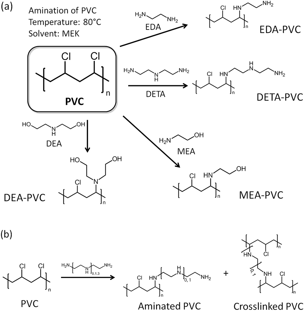 | ||
| Fig. 1 (a) Possible amination route of PVC with the selected amines; EDA = ethylenediamine, DETA = diethylenetriamine, MEA = monoethanolamine, DEA = diethanolamine and MEK = methyl ethyl ketone, and (b) a possible crosslinking mechanism for two products functionalized by diamine precursors. | ||
Ethylenediamine (EDA) was chosen as a model aminating agent for optimizing the process as other groups have tested a coupling reaction between EDA and PVC before.22–24 Analysis of several samples by elemental analysis consistently showed ca. 2.9 wt% of nitrogen indicating that the washing in a Soxhlet setup have led to reproducible results. The level of functionalization is also higher than reported previously due to the modified synthetic procedure.23,24
Fig. 2 shows the results of TGA/DSC measurements for unmodified PVC in airflow. An endothermic weight loss at 260 °C is attributed to the loss of monomers after the depolymerization.
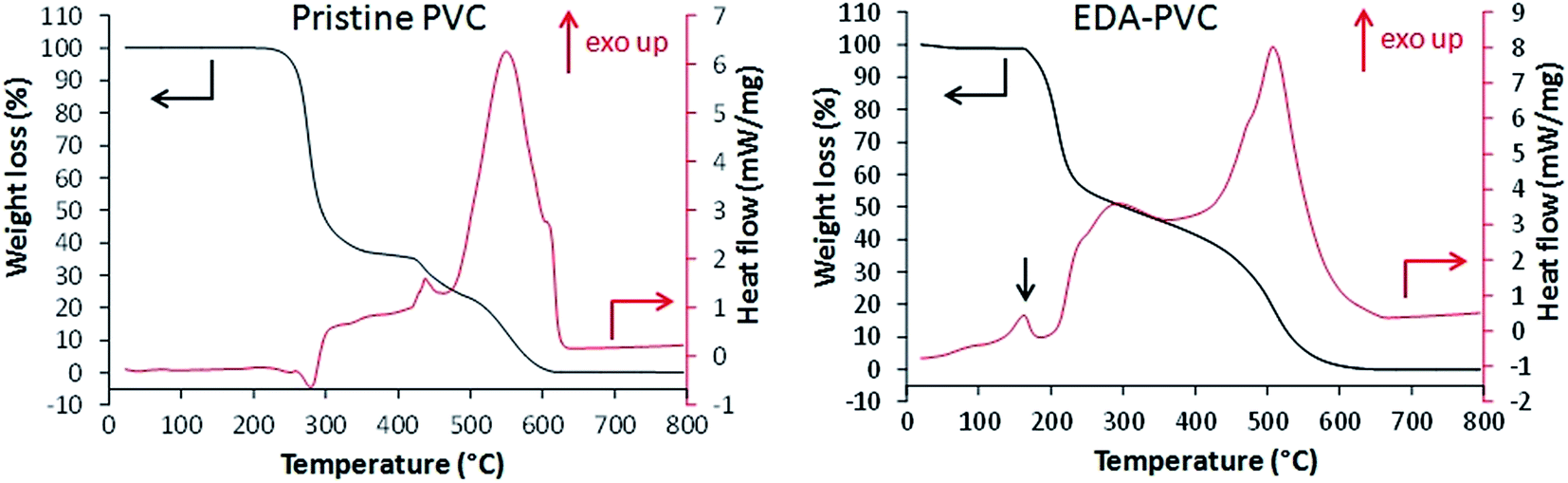 | ||
| Fig. 2 TGA (black, left scale) and DSC (red, right scale) for unmodified PVC and EDA–PVC. The exothermic transition at around 160 °C (indicated with a black arrow) appeared only with cross-linkable aminated PVC samples. | ||
Following exothermic steps are due to combustion of the polymer. EDA–PVC sample (Fig. 2) showed a small weight loss from 70 °C to ca. 160 °C due to the loss of the solvent. A minor exothermic peak appeared at around 170 °C which is likely due to a solid-phase transition (e.g. non-isothermal crystallization or polymorphic conversion)23,24 which is absent in the PVC polymer.27 A significant weight loss between 170 and 210 °C is accompanied by a corresponding exothermic peak on the DSC curve. This weight loss could be attributed to the possible loss of amine crosslinkers followed by a gradual depolymerization of PVC at higher temperatures. When compared with other aminated PVC samples prepared in this work (Fig. S1†), this is a common feature to the aminating reagents with potential for crosslinking/self-polymerizing, e.g. DETA–PVC (Fig. S1c†). MEA–PVC and DEA–PVC, which are unlikely to be crosslinked due to amination, showed no exothermic peak in this region (Fig. S1d and e†). Overall, the thermal analysis results indicate that aminated PVC materials are stable up to 140 °C without decomposition. The thermal stability is sufficient for thermal regeneration of the composites to be carried out sustainably in the associated carbon capture process.1
EDA–PVC/silica composites
Two mesoporous silica materials (SBA-15 and MCF) were chosen as the support for APVC due to their high surface area and mesoporous characteristic. The latter is important as high surface area materials with microporous structure (pore diameter < 2 nm) could suffer from pore blockage upon polymer deposition, hence reducing the gas adsorption capacity.1 The organic content of the APVC/silica composite samples was analyzed with TGA and elemental analysis with the results presented in Table 2.| Adsorbent | Organic content (% w/w) | BET surface area (m2 g−1) | Pore volume (cm3 g−1) | Pore radius (nm) |
|---|---|---|---|---|
| Unsupported EDA–PVC | 100 | 0 | 0 | 0 |
| SBA-15 | 0 | 481 | 0.98 | 4.4 |
| EDA–PVC/SBA-15 (4%) | 20 | 314 | 0.66 | 3.0 |
| EDA–PVC/SBA-15 (7%) | 22 | 295 | 0.58 | 2.8 |
| EDA–PVC/SBA-15 (19%) | 53 | 116 | 0.25 | 3.1 |
| MCF | 0 | 559 | 0.87 | 5.3 |
| EDA–PVC/MCF (4%) | 10 | 122 | 0.34 | 5.4 |
| EDA–PVC/MCF (7%) | 17 | 98 | 0.34 | 4.8 |
| EDA–PVC/MCF (19%) | 44 | 81 | 0.20 | 4.3 |
The observed nitrogen content is almost double when compared with the pristine EDA–PVC samples. For example, 4.4, 4.5 and 4.2% for 4%, 7% and 19% EDA loaded on MCF silica respectively versus 2.9 wt% observed for the pristine EDA–PVC products. This is consistent with the TGA results for products with different loadings of the EDA–PVC on SBA-15 and MCF supports (Fig. 3). In comparison with a pristine EDA–PVC sample (cf.Fig. 2) the TGA results suggested the remains of the solvent and unreacted amines were still present within the samples.
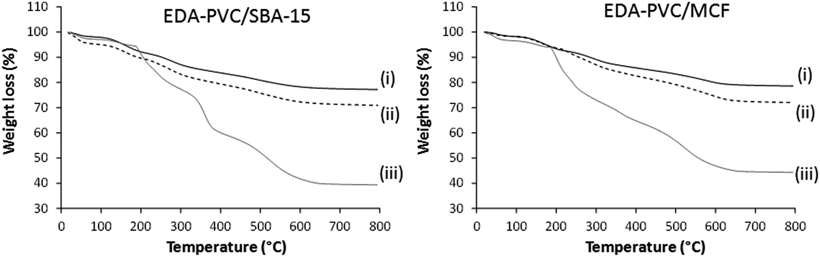 | ||
| Fig. 3 TGA curves for EDA–PVC/SBA-15 and EDA–PVC/MCF samples with (i) 4%, (ii) 7% and (ii) 19% loadings. | ||
Representative FTIR spectrum of EDA–PVC/SBA-15 in comparison with three other APVC composites is shown in Fig. 4. The highlighted broad absorbance bands at 3200–3500 cm−1 are assigned to NH stretching as well as OH stretching in cases of MEA–PVC and DEA–PVC coated samples. This indicates the similarity of the composite materials depending on the nature of the amination agent. Composite samples appear similar due to the similarity in the functional groups on the aminated PVC coatings.
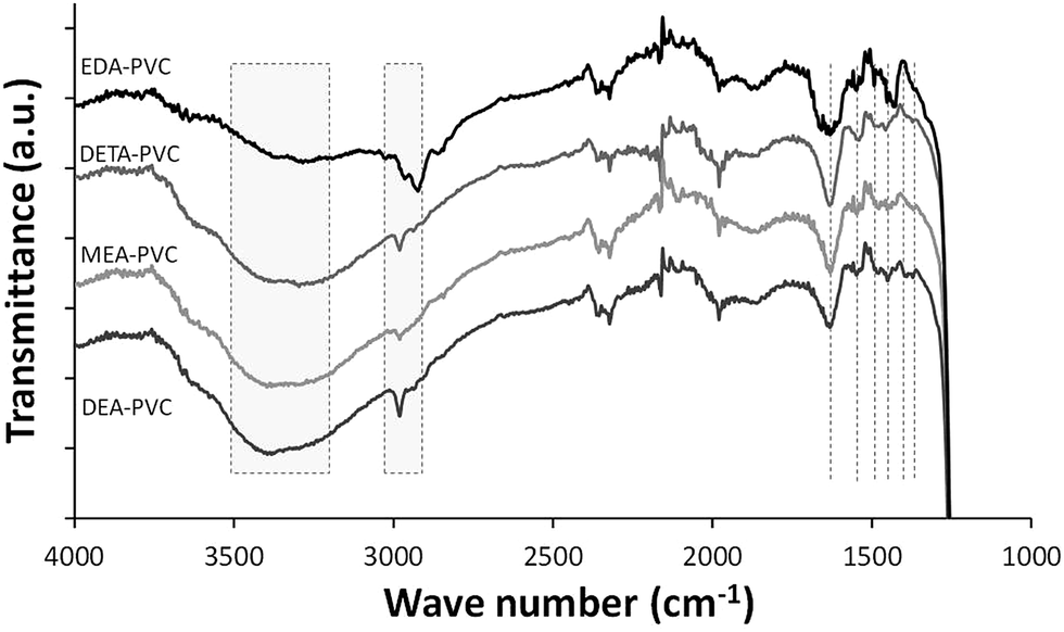 | ||
| Fig. 4 FTIR spectroscopy of EDA–PVC/SBA-15 (4%), DETA–PVC/SBA-15 (4%), MEA–PVC/SBA-15 (4%) and DEA–PVC/SBA-15 (4%). | ||
Absorption band at 2800–3000 cm−1 are due to the CH2 stretching modes, both on the PVC backbone and the amines. NH2 bending modes appear in ∼1540 cm−1 while bands at 1450–1480 cm−1 and ∼1350 cm−1 are assigned to CH2 bending modes. The strong absorbance band shown at 1750 cm−1 is due to the C![[double bond, length as m-dash]](https://www.rsc.org/images/entities/char_e001.gif) O stretching from the residual ketone groups from the solvents. Below 1200 cm−1, all spectra were dominated by the strong silica absorbance and therefore this data range was omitted. The retention of the solvent as indicated by FTIR data is expected considering the highly porous nature of the silica. However, the observed increase of the amount of the remains has very limited effect as a significant porosity and high surface area were retained, especially for products with 4% loading of APVC according to the surface area measurements.
O stretching from the residual ketone groups from the solvents. Below 1200 cm−1, all spectra were dominated by the strong silica absorbance and therefore this data range was omitted. The retention of the solvent as indicated by FTIR data is expected considering the highly porous nature of the silica. However, the observed increase of the amount of the remains has very limited effect as a significant porosity and high surface area were retained, especially for products with 4% loading of APVC according to the surface area measurements.
The adsorption/desorption measurement results of EDA–PVC composites with SBA-15 and MCF are shown in Fig. 5 with the results summarized in Table 2. In addition to surface area measurements all three supports (MCF, SBA-15 and fumed silica) were investigated by HRTEM (Fig. S2†). For all tested EDA–PVC composites there is a gradual decrease in the surface area and pore volume depending on the amount of amine-functionalised PVC used. In the case of SBA-15, which showed very well defined pores (Fig. S2†), the PSD data suggested that the pore radius was reduced from 4.4 nm to ca. 3 nm depending on the amount of the loaded EDA–PVC. The pore sizes of the MCF substrate were generally unaffected. The adsorption properties of fumed silica (f-SiO2) were also tested due its importance as a commercial standard. It showed a broad size distribution of mesopores with radius >1 nm. Interestingly, an increased polymer content (at 19%) for the fumed silica sample seemed to lead to larger pores at a radius >5.0 nm the phenomenon observed before for chitosan/fumed silica composites (Fig. S3†).25 It was also suggested that the pore structure of the adsorption sites plays a significant role on the total CO2 adsorption capacity, in addition to the available amine sites.29,30 Therefore, the pore structures of the composites were also mapped with the CO2 adsorption data as discussed in the next section. This allowed us to extrapolate the critical parameters for optimizing CO2 adsorption capacity. In contrast to SBA-15 and MCF control experiments carried out on EDA–PVC/fumed silica samples showed both the surface area and pore volume were hardly affected upon polymer deposition (Fig. S3†).
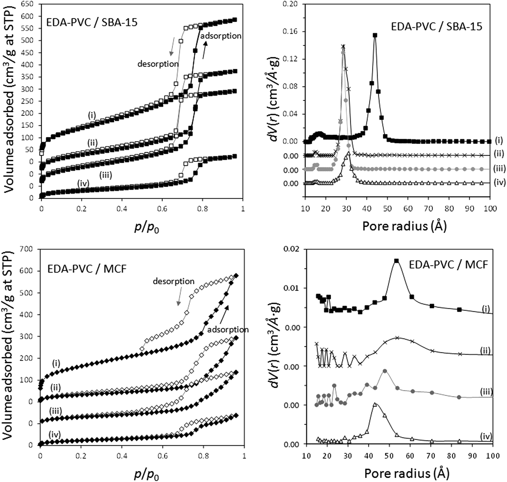 | ||
| Fig. 5 Nitrogen adsorption–desorption isotherms and pore size distribution (PSD) of MCF and SBA-15 composites with (i) 0%, (ii) 4%, (iii) 7%, (iv) 19% loading of EDA–PVC. Both the isotherms and PSD graphs were off-set along the y-axis for clarity. | ||
Gravimetric CO2 adsorption capacity of APVC composites
Carbon dioxide adsorption capacity of EDA–PVC on mesoporous silica composites was measured gravimetrically, e.g. by purging CO2/N2 mix (1:1 v/v, 50%) over the adsorbent samples at 25 °C and the results are shown in Fig. 6.
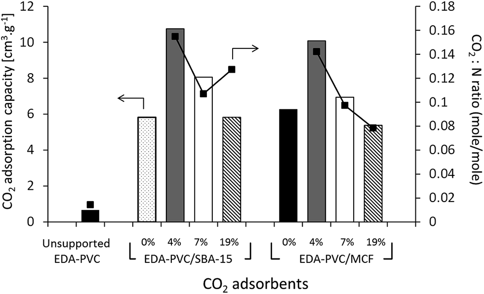 | ||
| Fig. 6 CO2 adsorption capacity at 25 °C measured by gravimetric method (left scale) and CO2:N ratio (right scale) for EDA–PVC/mesoporous silica samples depending on the amount of APVC. The CO2:N ratio is calculated from the CO2 adsorption capacity while the nitrogen content was calculated from CHN analysis. | ||
The gravimetric method for measuring the CO2 adsorption capacity was chosen here because it models the real carbon capture environment more closely than the volumetric method. As expected the unsupported EDA–PVC sample has shown a very low capacity below a measureable limit of our instrument of 0.73 cm3 g−1. On examining the CO2 adsorption capacity of EDA–PVC/SBA-15 (4%) composite has shown the highest adsorption capacity of 12 cm3 g−1. In line with the surface area measurements results the capacity to store CO2 gradually decreases as the polymer content increases. A similar trend was also observed for MCF series that showed maximum CO2 storage capacity peaking at 11 cm3 g−1. A comparable study on related amine-grafted mesoporous silicas MCM-41 with a capacity of 14 cm3 g−1 has also shown that an increase in pore size can enhance CO2 adsorption capacity while connectivity speeds up the adsorption process.30 In context of this study, EDA–PVC/MCF (4%) composites, which possess larger pores (between 4.0 to 8.0 nm in radius) and interconnecting porous structure, may be advantageous for carbon capture over 2D SBA-15 adsorbents.
The ratio was used as an indicator of the efficiency of the amount of CO2 adsorbed. Since the increase in polymer content did not yield higher CO2 adsorption capacity, the adsorption efficiency (or CO2:N) ratio decreases as the polymer content increases. One exception was EDA–PVC/SBA-15 (19%), which showed a higher CO2:N ratio than that of the sample with 7% loading. This was due to high organic residues content (53%) observed in this product (Table 2) which suggested an excessive amount of trapped solvent MEK in pores. This case also illustrated the disadvantage of 2D non-connected pore networks. EDA–PVC on commercial fumed silica was also tested for CO2 adsorption but the capacity shown was rather low (<1 cm3 g−1). Supporting the aminated PVC polymer on SBA-15 and MCF mesoporous silica with 4% polymer content showed the highest CO2 adsorption capacity among tested candidates. They therefore, meet three important criteria for an effective solid state adsorbent (1) being readily available on operational scale due to simple synthetic protocol; (2) possessing good adsorption capacity and (3) easy to handle with low environmental impact due to utilization of abundant waste material. However, the final criteria and ultimate challenge for any solid state adsorbent is its economic viability, e.g. an ability to regenerate with low energy duty. This was tested by analysis of the kinetics of adsorption/desorption on selected samples.
The representative CO2 adsorption kinetic profiles are shown in Fig. S5.† All samples reach saturation at 90 min and 90% of the adsorption capacity in 20 min. In all profiles, we observed an “initial step” followed by an increase in weight to saturation due to CO2 adsorption. One possible explanation for this observation is that the adsorption on the readily accessible sites on the outer surface or near the entrance of pores. Once these sites are occupied the pores become partially blocked and further adsorption is slowed down. When the CO2 molecules migrate towards the inner sites, pores open again and allow further adsorption. Such assumption is also supported by the assessment of the porosity of the adsorbents, e.g. with narrower pores on adsorbent showing a wider step. In particular, the EDA–PVC/MCF (4%) sample showed the smallest step due to its wider pores and interconnected porosity. Initial blockage became a less significant issue. The observed “non-linear” adsorption behaviour in Fig. S5† could be also attributed to change in nature of polymer coating around the exterior pores of the support due to interaction between CO2 molecules and amine sites during initial exposure to carbon dioxide. This may be accompanied by heat release leading to a reduction of diffusional resistance and as such, CO2 molecules could enter more facile into the interior pores of the support as manifested by a subsequent region of fast CO2 uptake. All adsorbents also recorded ∼100% desorption at 75 °C, which leads to a thermal energy duty at ca. 60 kJ molCO2−1, a considerable improvement from CaO and MEA solution. It should be noted that the TGA results suggested that the EDA–PVC products were stable up to 140 °C. Therefore higher regeneration temperature can be employed to speed up regeneration process. However, regeneration at a lower temperature of 75 °C can reduce the energy consumption, which is critical for a competitive CCS system.
The role of the aminating agent on the CO2 storage capacity
In addition to EDA, three other aminating reagents, diethylenetriamine (DETA), monoethanolamine (MEA) and diethanolamine (DEA) were tested and composites of aminated PVC on SBA-15 (all 4%) prepared from these reagents were analyzed. The structural data and CO2 adsorption capacity for these composite samples are summarized in Fig. 7 and Table S2.† N2 adsorption isotherms are given in Fig. S4.† | ||
| Fig. 7 CO2 adsorption capacity of APVC/SBA-15 (4%) composites depending on the nature of the aminating reagent. | ||
A decrease in adsorption capacity was observed for all samples compared with EDA–PVC/SBA-15. Generally, CO2 adsorption on amine groups under dry conditions leads to a formation of a carbamate following the chemical equation shown in Fig. 8a. Such adsorption may become less effective if the two amine groups are further apart.31 Among the aminating reagents that we used, ethylenediamine (EDA) appear to possess the best geometry for forming carbamate as illustrated in Fig. 8b. With an extra amine on the chain, diethylenetriamine (DETA) becomes less effective. Although widely used in liquid phase adsorption, mono- and diethanolamine (MEA and DEA) seem to be the least effective reagents for this task with DEA further hampered by steric hinderance due to the extra ethyl hydroxyl group. Compared with EDA–PVC/SBA-15, all three samples showed a higher surface area, higher pore volume and larger pore sizes. All of these structural parameters seem to be essential for a high CO2 adsorption capacity, but none of the samples outperformed EDA–PVC/SBA-15. This highlights that the distribution of amine sites on the adsorbents is critical to high CO2 adsorption performance.
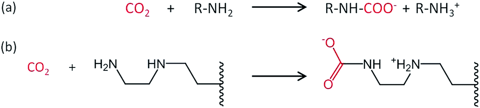 | ||
| Fig. 8 Proposed reaction schematic for CO2 chemisorption on a generic amine (a) and supported ethylenediamine (EDA) with carbamate formation in anhydrous condition (b).31 | ||
There are examples of composite materials prepared by coating polymers and mesoporous silicas that have been tested as adsorbents for CCS,1,13 with the research primarily dedicated to polyethyleneimine (PEI) functionalized silicas.31 PEI physically coated on MCF has achieved impressive CO2 adsorption characteristics with similar amine efficiency (CO2:N ratio) to results in this work. Further enhancement was also shown from the adsorption under humid conditions (1% water in flue gases).31 We also tested mechanical stability of EDA–PVC/SBA-15 (4%) sample, which showed the highest CO2 adsorption capacity among all samples tested in this work. The outcome of these experiments is summarized in Table S3.† Within the measurement error, there is a negligible difference between surface area, pore sizes and pore volume of the pristine and reground samples. There is a ca. 10% reduction in surface area accompanied by a similar reduction in pore volume for the pelletized sample while the pore sizes are the same. The resulting pellet is very robust and could be manipulated with the tweezers without breakage. This could be a useful property in industrial settings, e.g. for retrospective addition to existing CCS facilities.
There was a marginal difference between the TGA profiles of the untreated sample and the sample subject to hydrothermal treatment in boiling water for 1 hour (Fig. S6†). The resulting sorption characteristic of the hydrothermally treated sample after degassing at 100 °C is less than 5% lower when compared with the untreated composite indicating the good hydrothermal stability.
Hydrophobicity of the absorbents measured by contact angle tests
When compared with other amine-based adsorbents such as aminated mesoporous silicas,32 one distinctive property of PVC-based materials is their hydrophobicity. Hydrophobic adsorbents can be of particular use when the flue gas has excessive moisture content and the adsorbing system needs to avoid moisture. To study the hydrophobicity of the adsorbents, the contact angle of a water droplet on the adsorbent surface was measured. Fig. 9 shows the water droplet on the surface of fumed silica, EDA–PVC/SBA-15 (4%) composite. The pristine EDA–PVC product showed a high hydrophobicity as evident by a contact angle of 76.7°. SBA-15 is a highly hydrophilic support as apparent by the recorded contact angle of 15.4°. However, the minor 4% loading of EDA–PVC was sufficient to more than double the contact angle to 35.6°.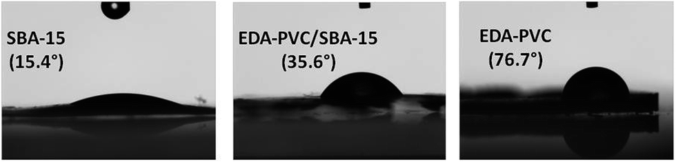 | ||
| Fig. 9 Images from the contact angle measurement experiment on SBA-15, EDA–PVC/SBA-15 (4%) and unsupported EDA–PVC polymer. | ||
The ability to control the hydrophobic–hydrophilic function is important as it could present an efficient way for stabilising compounds with high adsorption characteristics for CO2 sorption. For example, inducing hydrophobicity has been highlighted as a very efficient method in rendering compounds with limited stability (such as many MOFs) in elevated water content flues.33 Using PVC as a raw material for the preparation of adsorbent aiming at CO2 adsorption from flue gas could therefore present a unique advantage. Most solid state adsorbents such as zeolites, amine-grafted mesoporous silicas (MCM-41 and SBA-15) and many MOF systems are hydrophilic. High moisture content in flue gas is a natural by-product of combustion. For example, gas-fired power plants, preferred by developed countries, could generate a clean flue gas but with a much higher moisture content of up to 14%. As such, the moisture content could pose a negative effect on the efficiency of the adsorbents in a carbon capture system. This effect is particularly noticeable using zeolites as adsorbent as they are known to be deactivated in presence of moisture.34,35 Therefore, hydrophobic CO2 adsorbents which can be operated under high moisture content is a step in the right direction towards finding the ultimate CO2 adsorbent. Moreover, as most current amine-based solids selectively adsorb acidic gases such as CO2 on surface basic sites this adsorption can be interfered by other acidic gases such as SO2 and NOx. Modified PVC has already shown its potential in the separation of CO2 from SO2,36 making promising solid adsorbents for flues from coal power stations, e.g. with a high sulphur content which is particularly common in developing countries.
Conclusions
This work demonstrates a novel recycling/reusable pathway for waste PVC. Using a simple, robust route a range of hydrophobic aminated PVC were coated on silica support materials to form composites with high surface areas. Among these composites, EDA–PVC/SBA-15 with 4% w/w loading gave the highest CO2 adsorption capacity of 12 cm3 g−1 which also showed good mechanical and hydrothermal stability manifested by the marginal loss in surface area upon pressing to a compact pellet and after boiling in water. Higher polymer content seemed to cause pore blockage, which is a commonly observed feature in composites with mesoporous materials. The assessment of the adsorption/desorption kinetics for selected composites suggested an energy consumption of regeneration value of at 60 kJ molCO2−1. When compared with pristine supports the enhanced hydrophobicity of the composites suggests an interesting development opportunity for novel adsorbents capable of operating in the flue gas emitted from a gas-fired power plant with higher water content. Future research directions in this area should focus on optimising the aminated PVC–silica composites towards cost-efficiency, enhanced CO2 adsorption capacity, and CO2 selectivity under realistic simulated flue gas streams.Acknowledgements
AYG and JCM acknowledge the University of Glasgow for funding. GS, MSN and HHPY thank Scottish Carbon Capture and Storage (SCCS) program and the EPSRC, UK (EP/F034482/1 and EP/J02077X/1) for funding. We also thank Dr Cem Bayram (Hacettepe University, Ankara, Turkey) for his assistance in contact angle measurements. The data which underpin this work are available at http://dx.doi.org/10.XXXX/gla.researchdata.200 (will be completed after review when datasets are finalized).References
- G. Sneddon, A. Greenaway and H. H. P. Yiu, Adv. Energy Mater., 2014, 4, 1301873 CrossRef CAS; S. Choi, J. H. Drese and C. W. Jones, ChemSusChem, 2009, 2, 796 CrossRef PubMed.
- N. MacDowell, N. Florin, A. Buchard, J. Hallett, A. Galindo, G. Jackson, C. S. Adjiman, C. K. Williams, N. Shah and P. Fennell, Energy Environ. Sci., 2010, 3, 1645 CAS; F. Zeman, Energy Environ. Sci., 2007, 41, 7558 Search PubMed.
- M. Wang, A. Lawal, P. Stephenson, J. Sidders and C. Ramshaw, Chem. Eng. Res. Des., 2011, 89, 1609 CrossRef CAS.
- Y. S. Bae and R. Q. Snurr, Angew. Chem., Int. Ed., 2011, 50, 11586 CrossRef CAS PubMed.
- H. C. Chen, P. P. Zhang, Y. F. Duan and C. S. Zhao, Chem. Eng. J., 2016, 295, 218 CrossRef CAS.
- A. T. Vu, K. Ho, S. Jin and C. H. Lee, Chem. Eng. J., 2016, 291, 161 CrossRef CAS.
- J. K. Stolaroff, D. W. Keith and G. V. Lowry, Environ. Sci. Technol., 2008, 42, 2728 CrossRef CAS PubMed.
- A. Iizuka, K. Hashimoto, H. Nagasawa, K. Kumagai, Y. Yanagisawa and A. Yamasaki, Sep. Purif. Technol., 2012, 101, 49 CrossRef CAS.
- F. Barzagli, F. Mani and M. Peruzzini, Environ. Sci. Technol., 2016, 50, 7239 CrossRef CAS PubMed.
- M. Sharifzadeh, P. Bumb and N. Shah, Appl. Energy, 2016, 163, 423 CrossRef CAS.
- L. M. Romeo, I. Bolea and J. M. Escosa, Appl. Therm. Eng., 2008, 28, 1039 CrossRef CAS.
- F. S. Su, C. Y. Lu, S. C. Kuo and W. T. Zeng, Energy Fuels, 2010, 24, 1441 CrossRef CAS.
- J. Wang, L. Huang, R. Yang, Z. Zhang, J. W. Wu, Y. S. Gao, Q. Wang, D. O'Hare and Z. Y. Zhong, Energy Environ. Sci., 2014, 7, 3478 CAS.
- M. B. Yue, Y. Chun, Y. Cao, X. Dong and J. H. Zhu, Adv. Funct. Mater., 2006, 16, 1717 CrossRef CAS.
- T. C. Drage, C. E. Snape, L. A. Stevens, J. Wood, J. Wang, A. I. Cooper, R. Dawson, X. Guo, C. Satterley and R. Irons, J. Mat. Chem., 2012, 22, 2815 RSC.
- T. Tozawa, J. T. A. Jones, S. I. Swamy, S. Jiang, D. J. Adams, S. Shakespeare, R. Clowes, D. Bradshaw, T. Hasell, S. Y. Chong, C. Tang, S. Thompson, J. Parker, A. Trewin, J. Bacsa, A. M. Z. Slawin, A. Steiner and A. I. Cooper, Nat. Mater., 2009, 8, 973 CrossRef CAS PubMed.
- J. Hopewell, R. Dvorak and E. Kosior, Philos. Trans. R. Soc., B, 2009, 364, 2115 CrossRef CAS PubMed.
- C. B Zhou, W. J. Fang, W. Y. Xu, A. X. Cao and R. S. Wang, J. Cleaner Prod., 2014, 80, 80 CrossRef.
- L. Sorum, M. G. Gronli and J. E. Hustad, Fuel, 2001, 80, 1217 CrossRef CAS.
- M. A. Keane, ChemSusChem, 2009, 2, 207 CrossRef CAS PubMed.
- P. T. Williams and E. A. Williams, Energy Fuels, 1999, 13, 188 CrossRef CAS.
- S. C. Ma, N. A. Chaniotakis and M. E. Meyerhoff, Anal. Chem., 1988, 60, 2293 CrossRef CAS PubMed.
- M. S. Mohy Eldin, M. R. Elaassar, A. A. Elzatahry, M. M. B. Al-Sabah and E. A. Hassan, J. Appl. Polym. Sci., 2012, 125, 1724 CrossRef CAS; M. S. Mohy Eldin, H. A. El Enshasy, M. E. Hassan, B. Haroun and E. A. Hassan, J. Appl. Polym. Sci., 2012, 125, 3820 CrossRef.
- A. Singh, M. S. M. Rawat and C. S. Pande, J. Appl. Polym. Sci., 2010, 118, 876 CAS.
- G. Sneddon, A. Y. Ganin and H. H. P. Yiu, Energy Technol., 2015, 3, 249 CrossRef CAS.
- H. H. P. Yiu, M. A. Keane, Z. A. D. Lethbridge, M. R. Lees, A. J. El Haj and J. Dobson, Nanotechnology, 2008, 19, 255606 CrossRef CAS PubMed.
- J. Choi, S. W. Chun and S. Y. Kwak, J. Polym. Sci., Part B: Polym. Phys., 2007, 45, 577 CrossRef CAS.
- P. I. Ravikovitch and A. V. Neimark, J. Phys. Chem. B, 2001, 105, 6817 CrossRef CAS; J. C. Groen, L. A. A. Peffer and J. Pérez-Ramírez, Microporous Mesoporous Mater., 2003, 60, 1 CrossRef.
- R. Ryoo, C. H. Ko, M. Kruk, V. Antochshuk and M. Jaroniec, J. Phys. Chem. B, 2000, 104, 11465 CrossRef CAS.
- V. Zelenak, M. Badanicova, D. Halamova, J. Cejka, A. Zukal, N. Murafa and G. Goerigk, Chem. Eng. J., 2008, 144, 336 CrossRef CAS.
- W. J. Son, J. S. Choi and W. S. Ahn, Microporous Mesoporous Mater., 2008, 113, 31 CrossRef CAS; J. J. Ma, Q. M. Liu, D. D. Chen, S. Wen and T. H. Wang, J. Porous Mater., 2014, 21, 859 CrossRef; D. J. N. Subagyono, M. Marshall, G. P. Knowles and A. L. Chaffee, Microporous Mesoporous Mater., 2014, 186, 84 CrossRef.
- N. Hiyoshi, K. Yogo and T. Yashima, Chem. Lett., 2004, 33, 510 CrossRef CAS.
- N. Ding, H. W. Li, X. Feng, Q. Y. Wang, S. Wang, L. Ma, J. W. Zhou and B. Wang, J. Am. Chem. Soc., 2016, 138, 10100 CrossRef CAS PubMed; Z. J. Zhang, H. T. H. Nguyen, S. A. Miller, A. M. Ploskonka, J. B. DeCoste and S. M. Cohen, J. Am. Chem. Soc., 2016, 138, 920 CrossRef PubMed.
- J. C. Fisher, R. V. Siriwardane and R. W. Stevens, Ind. Eng. Chem. Res., 2011, 50, 13962 CrossRef CAS.
- F. Brandani and D. M. Ruthven, Ind. Eng. Chem. Res., 2004, 43, 8339 CrossRef CAS.
- K. Kim, S. Hong, J. Kim and H. Lee, AIChE J., 2014, 60, 2298 CrossRef CAS.
Footnote |
| † Electronic supplementary information (ESI) available: TGA/DSC, TEM, N2 adsorption measurements. See DOI: 10.1039/c7ta00389g |
| This journal is © The Royal Society of Chemistry 2017 |